
Related Manuals for eWON Flexy 205


Summary of Contents for eWON Flexy 205
- Page 1 ENGLISH ® Ewon Flexy 205 INSTALLATION GUIDE IG-0028-00 1.7 en-US Publication date 01/03/2024...
- Page 2 Important User Information Disclaimer The information in this document is for informational purposes only. Please inform HMS Networks of any inaccuracies or omissions found in this document. HMS Networks disclaims any responsibility or liability for any errors that may appear in this document. HMS Networks reserves the right to modify its products in line with its policy of continuous product development.
-
Page 3: Table Of Contents
1.3. Related Documents ......................1 1.4. Trademark Information ...................... 1 2. Product Summary ........................2 2.1. Introduction ........................2 ® 2.2. Modular Concept of the Ewon Flexy 205 ................2 ® 2.2.1. Ewon Flexy 205 ....................... 3 2.2.2. Extension Cards Detai ....................3 ®... - Page 4 5.2. Extension Card Insertion ....................22 ® 5.3. Powering On the Ewon Flexy 205 with its Extension Cards ............. 23 5.4. Multiple Extension Cards ....................23 5.4.1. Detection Order ....................... 23 5.4.2. Software Compatibility of Multiple Cards Combination ........... 24 5.5.
-
Page 5: Preface
1.1. About This Document 1.2. Document history Version Date Description 2018-01-12 Official release 2018-11-06 Changed: Flexy 205 label 2019-01-29 Changed: general review 2019-08-20 Changed: Safety, Environmental and Regulatory Information (page 5) 2020-01-02 Changed: Digital Output & Digital Inputs (page 31) 2022-08-02 Changed: product images &... -
Page 6: Product Summary
2.2. Modular Concept of the Ewon Flexy 205 ® As the name Ewon Flexy 205 suggests, it has been designed to enable numerous and various combinations by addition of extension cards. More information can be found in the Listing of Extension Cards (page 36) appendix. -
Page 7: Ewon ® Flexy 205
® 2.3. Features of the Ewon Flexy 205 ® The following section lists the different main features supported by the Ewon Flexy 205. • Open VPN • Talk2m connections • Data acquisition protocols (IO Servers) • Alarm management and notification •... -
Page 8: General Specification Of The Hardware Platform
Mounting Latch for DIN rail EN50022 compliant 2.5. Typical applications ® Some of the typical applications for the Ewon Flexy 205 are the following ones: • Remote access of Ethernet, serial and MPI devices • Industrial VPN router • Remote monitoring 2.6. -
Page 9: Safety, Environmental And Regulatory Information
3.4. Applicable Directives, Standards and Compliance ® The Ewon Flexy 205 belongs to class A Information Technology Equipment (ITE). In a domestic environment, this product may cause radio interference in which case the user might have to take appropriate measures. 3.4.1. Conformity to European Directives ®... -
Page 10: Applicable Safety Standards
3.4.3. FCC Compliance ® The Ewon Flexy 205 and its extension cards comply with Part 15 of the FCC Rules. Operating is subject to the following two conditions: • This device may not cause harmful interference • This device must accept any interference received, including interference that may cause undesired operation. - Page 11 Pull the slide lock (located at the bottom of the back-side of the unit) downwards and present the unit in front of the DIN rail. Tilt the Ewon upwards in order to hang it on the upper edge of the DIN rail by its hook. Gently tilt the unit downwards until it finds its original position.
-
Page 12: Earthing
Latch for DIN rail EN50022-compliant 3.5.4. Label ® The identification label of the Ewon Flexy 205 is placed on the right hand side of the housing. The different parts of the label are described below: IG-0028-00 1.7 en-US Page 8 of 37... -
Page 13: Hazardous Locations - Class 1 Division 2
Syntax of the Part Number: FLEXY12233_44AA [suffix] Position(s) Description Acce ptabl value FLEXY Name of the Ewon device model Only Flexy (constant) Single figure M2M Router Defines routing capabilities Two figures 4 configurable LAN/WAN Ethernet ports Defines the type of the motherboard... - Page 14 "H" stands for HazLoc (Hazardous Locations as opposed to OrdLoc - Ordinary Location) and refers to Class 1 Division 2 area. The FLEXY20500_00MAH has the same features as the Ewon® Flexy 205 (FLEXY20500_00MA) except it received official certification to be placed and used in a Class 1 Division 2 area.
-
Page 15: Internal Battery
Pull the slide lock (located at the bottom of the back-side of the unit) downwards and present the unit in front of the DIN rail. Tilt the Ewon upwards in order to hang it on the upper edge of the DIN rail by its hook. Gently tilt the unit downwards until it finds its original position. - Page 16 ® Field Implementation & Environmental Conditions Ewon Flexy 205 DIN rail mounting position Description DIN rail mounting bracket Wall mounting position Description Wall mounting bracket (suggested screw dimensions 4,2 x 32 mm) To ensure a proper ventilation of the equipment, a free gap of at least 2 cm must be respected in front of all upper &...
-
Page 17: Earthing
The OEM User Manual (for integrators) must provide clear instructions, to the OEM, explaining the labeling requirements, options and OEM User Manual instructions that are required. The host OEM User Manuel (Ewon's manual) must contain clear instructions on how end users can find and/or access the module and the FCC ID. -
Page 18: Hardware Description
4. Hardware Description 4.1. Label ® The identification label of the Ewon Flexy 205 is placed on the right hand side of the housing. The different parts of the label are described below: Label Definition Part Number (see syntax in the table below) -
Page 19: Mechanical Dimensions
® Mechanical Dimensions Ewon Flexy 205 Marks Marks Description Conformité Européenne or European Conformity (EC) UL Recognized - Underwriters Laboraties 4.2. Mechanical Dimensions Figure 2. Mechanical Dimensions In the above picture: • Unit: Dimensions are in millimeters (mm). • Accuracy: Suited only for implementation drawings (rounded @ full mm). -
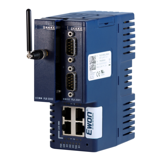
Page 20: Physical Interface
Physical Interface Ewon Flexy 205 4.3. Physical Interface ® This section addresses the interface that represents the Ewon Flexy 205. The items numbered in the image below are explained subsequently in separate paragraphs. Figure 3. Base Unit Interface LED panel. -
Page 21: Reset Button
Figure 4. LED Panel Example of a Flexy 205 4.3.2. Reset Button The reset button allows the reset of the Flexy 205 partially (Reset Level 1) or completely (Reset Level 2). For the reset procedures check Resetting the Flexy 205 (page 28). -
Page 22: Lan / Wan Ethernet Ports
Green flashing = Ethernet traffic (Rx and Tx) Ethernet activity on port 2 (same as above) Ethernet activity on port 3 (same as above) Ethernet activity on port 4 (same as above) Figure 6. LED Panel of the Flexy 205 IG-0028-00 1.7 en-US Page 18 of 37... -
Page 23: Extension Cards
® Extension Cards Ewon Flexy 205 5. Extension Cards Picture Reference & name Slot compatibility Maximum supported Installation Guide FLA 3301 2 Serial-Ports ●●○○ IG-0016-00 FLX 3101 Ethernet 10/100 ●●●● IG-0017-00 FLX 3402 8DI-4AI-2DO ●●●● IG-0030-00 FLB 320A 4G EU ○○●●... - Page 24 ® Extension Cards Ewon Flexy 205 Picture Reference & name Slot compatibility Maximum supported Installation Guide FLB 3203 4G Verizon IG-0025-00 ○○●● FLB 3208 4G NA FLB 3208 4G NA IG-0033-00 FLB 3209 4G APAC ○○●● IG-0032-00 FLB 3601 USB ○○●●...
-
Page 25: Slot Compatibility
NOTICE ® The Type A, Type B or Type X slots are important for Flexy 10x and 20x. The Ewon Flexy 205 is compatible with all extension cards and doesn't rely on the reference code of the extension cards to position them. -
Page 26: Extension Card Insertion
Wait 30 seconds after turning off the equipment before inserting (or removing) an extension card in ® order to avoid possible damage to the Ewon Flexy 205 and the extension cards. Remove the slot filler of the location the new card will be inserted. To do this, press on both ends of the cover, note that the hooks are off-centered. -
Page 27: Powering On The Ewon ® Flexy 205 With Its Extension Cards
5.4.1. Detection Order ® The boot sequence of the Ewon Flexy 205 includes an automated detection of the inserted extension cards. This detection is done sequentially, one slot after the other, starting from the left to the right (when holding the ®... -
Page 28: Software Compatibility Of Multiple Cards Combination
5.4.2. Software Compatibility of Multiple Cards Combination ® The Ewon Flexy 205 allows the insertion of multiple extension cards of the same type. Some configurations including multiple extension cards, even if mechanically acceptable, are not supported by the embedded ®... - Page 29 ® Ethernet Extension Card - FLX 3101 Ewon Flexy 205 NOTICE This switch to 4 LAN ports occurs only when an FLX 3101 is inserted. This doesn’t happen if a WiFi (FLB 3271) or a 3G / 4G (FLB 3202 / 3203 / 320A / 3208) extension cards are plugged-in.
-
Page 30: Ip Address & Access To The Web Configuration
Related Document (page 1) chapter. 6.3. Connecting to the LAN IP Address ® Flexy 205 by using Ewon companion tool Ebuddy which can be Establish the first communication with the Ewon downloaded from www.ewon.biz/support. ® Connect the LAN port #1 of the Ewon Flexy 205 to the computer point-to-point or through a network provided ®... -
Page 31: Web Interface
Save. ® At the very first boot of the Ewon Flexy 205 or after a reset level 2 and after successfully logging in, an interface language selection will be proposed. ® A configuration wizard will be proposed afterwards which sets the configuration of the Ewon Flexy 205 but also the connection to the Talk2m environment. -
Page 32: Resetting The Ewon ® Flexy 205
Wait approximately 30 seconds until the reset procedure is completed. ® Flexy 205 restarts automatically and the unit is ready to be used, the USR LED blinks green The Ewon slowly. 7.3. Second Level Reset (Factory Reset) ®... -
Page 33: Reset Impact Matrix
Check if the auto test is successful, the USR LED blinks red following a pattern of 200ms ON and 1,5 sec OFF. ® The Ewon Flexy 205 does not restart in normal mode by itself and remains in this diagnose mode. ® Power the Ewon Flexy 205 OFF and ON again to reboot the unit in normal mode. -
Page 34: Appendix A. Appendix
The Ewon Flexy 205 must be powered by a 12-24Vdc 100w max. certified for 60°C and for altitudes up to 2000m for conformity its more recent UL/IEC standards or by a safety Low Power Supply (LPS) in accordance with clause 2.5 of its more recent UL/IEC standards. -
Page 35: Digital Output & Digital Inputs
The Digital Output is activated by an open drain MOSFET transistor driven by an optocoupler. The maximum current flow inside this transistor has a value above the one specified in the Ewon, in order to cope with the switching power losses. -
Page 36: Flexy 205 Products Overview
® Flexy 205 Products Overview Ewon Flexy 205 2. Flexy 205 Products Overview IG-0028-00 1.7 en-US Page 32 of 37... -
Page 37: Extension Cards
® Flexy 205 Products Overview Ewon Flexy 205 2.1. Extension Cards Picture Reference & name Slot compatibility Maximum supported Installation Guide FLA 3301 2 Serial-Ports IG-0016-00 ●●○○ FLX 3101 Ethernet 10/100 IG-0017-00 ●●●● FLX 3402 8DI-4AI-2DO ●●●● IG-0030-00 FLB 320A 4G EU IG-0034-00 ○○●●... - Page 38 ® Flexy 205 Products Overview Ewon Flexy 205 Picture Reference & name Slot compatibility Maximum supported Installation Guide FLB 3203 4G Verizon IG-0025-00 ○○●● FLB 3208 4G NA FLB 3208 4G NA IG-0033-00 FLB 3209 4G APAC ○○●● IG-0032-00 FLB 3601 USB ○○●●...
-
Page 39: Flexy 205 Isolation Scheme
As explained in Software Compatibility of Multiple Cards Combination (page 24), the number of cards of the same type supported by the firmware is indicated in this table. 3. Flexy 205 Isolation Scheme 3.1. Base Unit Flexy 205 Connector shielding... -
Page 40: Listing Of Extension Cards
® Flexy 205 Isolation Scheme Ewon Flexy 205 IMPORTANT Serial ports GND = DGND Figure A.3. Isolation Scheme for the Base Unit Based on the above picture: • External and internal power supplies are isolated from each other (1.5kV). • DI signals: isolated from DO signals, PGND and DGND (optocoupler). - Page 41 ® Flexy 205 Isolation Scheme Ewon Flexy 205 IMPORTANT AI-GND = DGND FLA 3301 – Dual Serial Ports Serial port signals: isolated from PGND only. Connector shielding: connected to Earth. IMPORTANT Serial ports GND = DGND FLC 3701 – MPI Port MPI port signals: isolated from PGND only.
Need help?
Do you have a question about the Flexy 205 and is the answer not in the manual?
Questions and answers