
Related Manuals for FILTRINOV MX


Summary of Contents for FILTRINOV MX
- Page 1 SELF-CONTAINED SINGLE-PIECE FILTRATION UNIT Installation and operating instructions. Read carefully and retain for future reference. MX RANGE...
-
Page 2: Table Of Contents
CONTENTS Recommendations ..............P.3 Technical description of the filtration unit ....P.4 Installing the filtration unit ............. P.5 Filtration unit power supply ........... P.6 LED Light ..................... P.7 Setting the timer ................P.7 Starting the filtration unit ............P.8 Pool-Earth .................. -
Page 3: Recommendations
(usually 230 Volts AC). FOREWORD : Thank you for purchasing this MX 18/25 filtration unit and for your trust in our com- pany. You can rest assured that every effort has been, and will continue to be made to bring you complete satisfaction. -
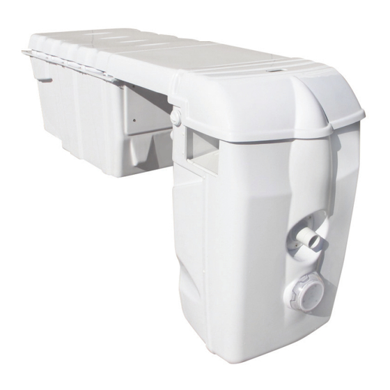
Page 4: Technical Description Of The Filtration Unit
TECHNICAL DESCRIPTION OF THE FILTRATION UNIT Filter access lid. Multi-directional, high-fl ow nozzle. LED light. Dual fi lter cartridge housing incl. 2 leaf baskets. Two suction skimmers. Massage function air-fl ow control. Counter-current system switch (pneumatic) In-ground section containing : Pumps/Control panel/Optional items. -
Page 5: Installing The Filtration Unit
INSTALLING THE FILTRATION UNIT • Dig a pit into which the filtration unit tank will be placed. • Remove the filtration unit from its packaging and place it carefully in position straddling and resting on the pool structure. • Make sure the front, pool-side of the unit is positioned fully perpendicular to the pool wall. -
Page 6: Filtration Unit Power Supply
30mA RCD (not included). Use a 3-wire cord, earth-live-neutral, with a 1.5 or 2.5 mm² section if less than 30 linear metres. MX panel without options WP3/HEM Front-mounted filtration and lighting controls 3 P Flush-mounted socket... -
Page 7: Led Light
LED LIGHT Standard Your filtration unit includes a light as standard. Optional A MULTICOLOUR LED light option is also available in 11 non-animated colours incl. white and with 5 sequence programmes (remote control included) (Manufacturer’s guide included) SETTING THE TIMER •... -
Page 8: Starting The Filtration Unit
They can also disrupt the treatment probes, resulting in incorrect amounts of product being injected. This is why FILTRINOV has included a pool earth with these products. Screw it into the threaded attachment point provided and connect it to the earth rod with a Ø... -
Page 9: Filtration : Operating Principle
Refit the cartridge once it is clean. Your MX includes a cartridge housing at the bottom of the filter holder to fit the cartridge. Turn the cartridge a quarter turn downwards to slot it into place in the filter holder. -
Page 10: Vacuum Point For Manual Suction Cleaner
VACUUM POINT FOR MANUAL SUCTION CLEANER OR HYDRAULIC AUTOMATIC CLEANER • Connect one end of the hose to the suction cleaner ; • Hold the suction cleaner by the handle and insert it into the pool ; • Gradually insert the hose into the water until the water pushes out the air (tip : you can fill the hose with water by placing its tip in front of the return nozzle with the unit running) ;... -
Page 11: Optional By-Pass
OPTIONAL BY-PASS (3-way valve) The by-pass consists of a 3-way valve and a branch Tee. You are advised to seal the pipe entries in order to prevent water getting into the tank. Your heat pump is connected to the filtration unit by a Ø 50 PVC pipe. - Page 12 OPTIONAL COUNTER-CURRENT SYSTEM (CCS) • To switch on the counter-current system, press the pneumatic push-button located on the side of the underwater section. • To stop the counter-current system, press the push-button again. Counter-current system pipework : Non-return valve Filtration pump pump Filtration + CCS...
- Page 13 BY PASS + CHLORINATOR + PH CONTROL • The by-pass consists of a 3-way valve and a branch Tee. You are advised to seal the pipe entries in order to prevent the ingress of water into the tank. • Chlorinator consists of a cell and a chlorinator controller. •...
-
Page 14: Winterising And Pump Disassembly
WINTERISING & PUMP DISASSEMBLY • Active Winterising : An actively winterised pool continues to operate at a slower than normal rate throughout wintertime. This is the recommended winterising procedure in less cold regions. If you live in a harsher winter climate, you should choose to passively winterise your pool instead. - Page 15 CAUTION : ALWAYS CUT THE ELECTRICAL POWER UPSTREAM OF THE FILTRATION UNIT FIRST • Undo the 2 bleed screws to drain the water from the pipes and prevent a siphon forming. • Unscrew the pump inlet and outlet unions. • Wait for the water to drain through the hole in the bottom of the tank.
-
Page 16: Faq/Trouble Shooting
TROUBLE SHOOTING FILTERS/PUMPS/CCS PROBLEM : Low pressure flow and/or air bubbles in the pumped water flow CAUSE SOLUTION • SITUATION 1: The cartridges are dirty but not clogged. Clean the cartridges at more regular intervals (once every fortnight) •SITUATION 2: Renew the cartridges if they are clogged Cartridges •SITUATION 3: If you are using a flocculent or anti-algae treatment, lower the water level by 20 cm and renew the cartridges Clean the debris from the baskets at regular intervals and clean or renew the Netskims (skimmer socks/nets) - Page 17 TROUBLE SHOOTING PROBLEM : The pump cuts out and starts up again later CAUSE SOLUTION • To prevent the pump and its thermal circuit breaker from overheating, we advise you to programme your filter system to run for no more than 3 or 4 hours at a time with a 1-hour break between operating periods. Example : Water temperature: 24°C;...
- Page 18 TROUBLE SHOOTING LIGHTING PROBLEM : The light is blinking. CAUSE SOLUTION The light is reaching the end of its service life or is not/no longer watertight. Replace the light using a niche (feed-through) system. Light AUTOMATIC WATER TREATMENT PROBLEM : The electrolyser unit does not switch on.. CAUSE SOLUTION Electrolyser circuit breaker in...
- Page 19 TROUBLE SHOOTING PROBLEM : The pH probe is giving incorrect readings. CAUSE SOLUTION •A stray current is probably interfering with your probe reading. Use a glass water to check if this is the case : 1. Dip the probe into a glass of tap water (pH level between 7.5 and 8.0) and see if the reading is consistent. 2.
Need help?
Do you have a question about the MX and is the answer not in the manual?
Questions and answers