Table of Contents
Advertisement
Quick Links
Advertisement
Table of Contents

Related Manuals for CleanControlling CPS3 apex

Summary of Contents for CleanControlling CPS3 apex
- Page 2 Original operating instructions – FESTOOL mobile dust extractor CTL MINI I, CTL MIDI I, CTL MINI, CTL MIDI CleanControlling GmbH Gehrenstrasse 11 a D-78576 Emmingen-Liptingen Tel.: +49 (0)7465 929678-0 Fax: +49 (0)7465/929678-10 Website: www.cleancontrolling.com/en/ Email: info@cleancontrolling.de Copyright © 2019 CleanControlling GmbH...
-
Page 3: Table Of Contents
Contents Table of contents 1. Basic safety instructions 1.1. Obligation to instruct 1.2. Conformity, guidelines and directives 1.3. Safety symbols and representations used 1.3.1. Warnings and warning signs 1.3.2. Signal words 1.3.3. Other symbols 1.3.4. Mandatory symbols 1.4. Operating instructions 1.5. - Page 4 Contents 5.4. Switching on the device 5.4.1. Connecting the remote control to the suction unit 5.5. Reset on the remote control 5.6. Deleting all saved Bluetooth connections of the suction unit 6. Particle suction extraction process 6.1. Screwing on or replacing the particle collection jar 6.2.
-
Page 5: Basic Safety Instructions
CleanControlling GmbH does not accept any liability or warranty for any damage caused by staff who have received inadequate instructions or who have not received any instructions, as well as in case of changes to the system that do not comply with the specified requirements. -
Page 6: Conformity, Guidelines And Directives
1.2. Conformity, guidelines and directives The device and its components, modules and assembly groups comply individually and as a whole with the current applicable safety standards as specified in European Union CE Directives (see the enclosed EC Declaration of Conformity). 1.3. -
Page 7: Other Symbols
1.3.3. Other symbols The following symbols are also used: The text next to this symbol provides additional important information. This symbol requires you to take action. • This symbol is a bullet point for lists. 1.3.4. Mandatory symbols Mandatory instructions and symbols are used within warning symbols or precede highly important points in the main text. -
Page 8: Obligation And Liability
The suction unit or its suction hose may only be used in combination with the particle suction extraction system. To ensure the operational safety of the system, it may only be operated in accordance with its intended use and in a perfectly safe condition. -
Page 9: Foreseeable Misuse
• Unauthorized structural changes to the device. • Unauthorized modification of the operating parameters. • Insufficient monitoring of device parts that are subject to wear. • Improperly performed repairs and force majeure. 1.5.2. Foreseeable misuse Any use other than that specified under “Intended use” or which goes beyond this is considered improper use and is prohibited. -
Page 10: Electrical Hazards
Wear the prescribed protective equipment, consisting of safety shoes, at all times when working on the system. 1.6.1. Electrical hazards When working on the electrical equipment, danger to life exists due to electrical voltage. Caution – ESD-protected area: Observe preventive measures when handling components susceptible to damage from electrostatic discharge. -
Page 11: Hazard Due To Noise
1.6.3. Hazard due to noise Depending on local conditions, a higher sound pressure level may occur, causing noise- induced hearing loss. For these areas, the operator must provide the operating personnel with appropriate protective equipment and take protective measures in accordance with the Worker Noise Protection Directive 2003/10/EC. -
Page 12: Organizational Measures
1.6.7. Organizational measures The operator must provide the required personal protective equipment. All safety systems must be checked on a regular basis. The operator is obliged to appoint a person in charge who is responsible for safe operation of the device and for coordination of all work on the device. -
Page 13: Structural Changes To The Device
• You must dispose of the device as electronic waste once its service life has come to an end. Ask your local waste management company or CleanControlling where your particular collection point is. • Sort different materials such as plastic, metal and electronic components and dispose of them separately. -
Page 14: Change Of Owner
• Dispose of all components safely and correctly as per applicable local regulations on health, safety and the environment. 1.6.15. Change of owner Ensure that all components, including spare parts and accessories, are also given to the new owner if you sell the device. These components include all operating instructions, manuals, maintenance instructions, other instructions, modifications and additions that you have received as an owner. -
Page 15: Further Use Of Components After Suction Extraction
1.8. Further use of components after suction extraction If the components sampled by the particle suction extraction system are reused, the operator is responsible for carrying out subsequent tests to ensure their integrity. Particle suction extraction system / Item no.: 6006100 15 / 85 Date 06.12.2023 / Version 1... -
Page 16: Description Of The Extraction Principle
2. Description of the extraction principle The mobile particle suction extraction system is used to extract dry, adherent particles from large surfaces and from specific control areas on workpiece carriers and in process environments. The particles are released from the surface by suction using nozzles and brush and then sucked in by means of a mobile extractor. -
Page 17: Particle Suction Extraction With Cyclone And Filter Unit (Variant I)
Selecting the appropriate method according to the degree of contamination 2.1. Particle suction extraction with cyclone and filter unit (variant I) Variant I-A: The extracted particles (2) are separated in a clean laboratory bottle (3) via the cyclone unit (1). The filter unit (4) provides overload protection using a special analysis filter (> 5 µm) to protect against an excessively high particle load. -
Page 18: Particle Suction Extraction Without Cyclone Unit, Directly Onto The Filter Unit (Variant Ii)
Suction extraction via the cyclone unit is particularly suitable for large component surfaces with greater particle loads. This dry particle extraction system is very economical compared to wet extraction due to the absence of liquid extraction media, the reduced logistics workload and the easily delimited control areas. -
Page 19: Structure
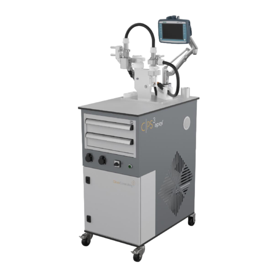
3. Structure 3.1. Mobile trolley Operating panel Extraction system ESD-capable worktop Drawer inserts with extraction equipment Main switch Power button Control unit ESD-capable fixed castors Particle suction extraction system / Item no.: 6006100 19 / 85 Date 06.12.2023 / Version 1... -
Page 20: Mobile Extractor Rear
3.2. Mobile extractor REAR Adjustable panel holder Harting connector Laboratory spray bottle Suction hose Power connection cable Suction unit flap Particle suction extraction system / Item no.: 6006100 20 / 85 Date 06.12.2023 / Version 1... -
Page 21: Particle Suction Extraction System Without Cyclone Unit
3.3. Particle suction extraction system without cyclone unit Particle suction extraction system / Item no.: 6006100 21 / 85 Date 06.12.2023 / Version 1... -
Page 22: Particle Suction Extraction System With Cyclone Unit
3.4. Particle suction extraction system with cyclone unit Union sleeves Connection hose Filter unit upper part Clamping lever Flushing unit Filter unit Filter unit upper part holder Flushing unit holder ESD spray bottle Cyclone unit Bayonet closure Wet cleaning adapter connection Nozzle bracket Dry adapter... -
Page 23: Device Transport
4. Device transport When transporting the device, the following must be observed. To protect the device from contamination by external particles, the protective hood should be pulled over it. During transport of the system, it may only be moved at walking speed. Ensure that the clamping levers and union nuts are correctly closed, otherwise, machine components may unexpectedly come loose and fall down. -
Page 24: Initial Operation
5. Initial operation Wrap the components to be tested in ESD-protected packaging while carrying out work on the C|PS³ system or remove the C|PS³ system from the EPA environment to prevent any damage to the components to be tested. 5.1. Mobile trolley To put the C|PS³... -
Page 25: Suction Unit
5.2. Suction unit Preparing suction unit 1 Preparing suction unit 2 Open the flap (3) of the suction unit and remove the power cable. Then guide approx. 1.5 m of the suction hose (4) out through the recess provided for this purpose and close and lock the flap (3) again. - Page 26 Connect the power cable to the socket (1). Guide the suction hose through the opening (2) of the trolley and connect it to the connection (3) provided for this purpose. Make sure that the main switch of the device is in the “OFF” position, otherwise, electric shocks may occur.
- Page 27 Open the flap of the suction unit again and insert the control cable (1) into the device. Slightly lift the suction hose and connect the connector (2) of the control cable to the suction unit. Place the suction hose back into the suction unit and close the suction flap. ...
- Page 28 If the Harting connector (4) should not be connected to the suction system, connect it to the plug-in unit. Tighten the brackets (5) at the top and bottom to fix the connector on the device. The brackets must be closed firmly, otherwise, measurement errors may occur.
-
Page 29: Extraction System
5.3. Extraction system Attaching the suction unit connection hose Attach the connection hose to the suction unit on the C|PS³. When you do so, the arrow (6) on the connection hose must face the hose connection slot (7). Connecting the Harting connector The brackets must be closed firmly, otherwise, measurement errors may occur. -
Page 30: Initial Operation With Cyclone Unit
5.3.1. Initial operation with cyclone unit Interconnecting cyclone unit and filter unit Remove the protection plug and interconnect the cyclone unit (1) and the filter unit (2) with the 0.5 m connection hose. Insert the connecting hose until it stops and turn the union sleeve tightly. If the union sleeves are not tightly tightened, this may cause particle loss or malfunction of the device. - Page 31 Attaching the suction hose (1 or 2 m) After removing the protection plug, connect the suction hose to the cyclone unit and tighten the union sleeve (3). Attaching the suction nozzle Attaching the Bluetooth remote control Attach the required suction nozzle suitable for the intended particle suction extraction process.
-
Page 32: Initial Operation Without Cyclone Unit
5.3.2. Initial operation without cyclone unit Attaching the suction hose and suction nozzle Open the lower clamping lever (1) and place the upper part of the filter unit (2) in the holder (3). Insert the filter (4). Place the flushing unit (5) and actuate the lower clamping lever. ... -
Page 33: Switching On The Device
If the union sleeves and clamping levers are not tightly tightened, this may cause particle loss or malfunction of the device. 5.4. Switching on the device Main switch and screen Turn the main switch (1) to “ON”. Then press the button (2). The device is ready for operation as soon as the button is lit, the screen is on and the main menu is visible on the screen. -
Page 34: Reset On The Remote Control
Function keys and indicators of the operating panel and remote control Follow the steps below to connect a remote control that is not yet connected (or after a reset) to the suction unit: In stand-by mode, press and hold the connection key (1) of the suction unit for 3 seconds. -
Page 35: Deleting All Saved Bluetooth Connections Of The Suction Unit
5.6. Deleting all saved Bluetooth connections of the suction unit If required, all saved device connections can be deleted by following the steps below: Press and hold the connection key (1) for at least 3 seconds. Connection indicator (2) flashes quickly. ... -
Page 36: Particle Suction Extraction Process
6. Particle suction extraction process The extraction process shown here is performed with the cyclone unit and is also valid for an extraction process without a cyclone unit. If necessary, the device must be cleaned and a blank value determined before particle suction extraction –... -
Page 37: Attaching Or Replacing The Particle Trap
6.2. Attaching or replacing the particle trap In case of less severe contamination, it is also possible to extract particles from the cyclone unit directly onto the particle trap. Attaching the particle trap If necessary, unscrew particle collection jar and screw on adapter (13) for the particle trap. -
Page 38: Flushing The Mesh Filter
Removing and archiving the mesh filter Then analyze the mesh filter with a microscope (as per ISO 16232). The particles on the mesh filter removed from the filter unit complement the microscopic analysis. Insert the new mesh filter (15) into the filter clamping point. ... - Page 39 Flushing to optimize particle distribution Left before flushing and right after flushing Press the “Flush” button. Loosen the upper clamping lever (1) and remove the upper part. Fill the liquid to a height of approx. 2 cm using a spray bottle (2). ...
-
Page 40: Carrying Out The Particle Suction Extraction Procedure
Connect the suction hose to the drying adapter (3) and then start dry suction by pressing the “Re-suction” button. Remove the filter accordingly and place it on the labeled filter frame. 6.5. Carrying out the particle suction extraction procedure Extracting particles ... -
Page 41: Selecting The Correct Suction Level
During suction extraction, ensure that you take samples from components or surfaces from the outside to the inside and from top to bottom. Re-suction must be carried out for approx. 30 sec. after suction extraction and before each change of a nozzle variant (including removing the particles from the brush attachments) to ensure that all particles extracted from the component can be found in the analysis. -
Page 42: Instructions On Using The Suction And Brush Nozzles
6.7. Instructions on using the suction and brush nozzles Suction nozzle ✓ Correct distance and angle to hold the suction nozzle Incorrect distance and angle to hold the suction nozzle When using the suction nozzle or flat nozzle, ensure that you don't block the nozzle by closing the suction nozzle head. - Page 43 Brush nozzle ✓ Applying the brush nozzle correctly Applying the brush nozzle incorrectly When using the brush nozzle, ensure that the brush nozzle is not applied at an angle. The contact pressure should not cause the brush hairs to bend. You should aim to apply the brush nozzle at a right angle.
- Page 44 Flat nozzle ✓ Applying the flat nozzle correctly Applying the flat nozzle incorrectly When using the flat nozzle, ensure that the contact pressure does not cause the brush hairs to bend. You should aim to guide the flat nozzle with your hand parallel to the component surface.
-
Page 45: Operating Parameters
6.8. Operating parameters The volume flow of the particle suction extraction system is measured and calculated using the differential pressure measurement method below the mesh filter. The volume flow is an indicator of the reproducibility of the selected process parameters. The following guide values are given when using the suction unit, 5 µm mesh filter and the marked operating point: Volume flow when using the 5 µm mesh filter... -
Page 46: Cleaning
7. Cleaning Clean the particle suction extraction system thoroughly before initial operation and between individual measurements. Particles from previous tests or contaminants may distort the analysis results. For this reason, it is important to remove all remaining particles from the system as far as possible. - Page 47 Attachment point for the alcohol-soaked Inserting through the attachment point cleaning cloth Unscrew the cone (3) of the cleaning wire (1) and wrap or fold over the alcohol- soaked cleaning cloth about 6.5 cm at one corner (see photo). Punch a hole in the folded corner with the thread of the cleaning wire lower section (2) (see the x in the photo).
- Page 48 Disassembly and cleaning Cleaning wire cone with screw Thread to be cleaned You can disassemble the cone (4) by hand, using a screwdriver and open-end spanner if necessary. Blocked cone thread Removing cleaning cloth remains The cleaning wire cone features a small screw (5). You can remove the screw (5) to clean the cone thread with a pointed object.
-
Page 49: Cleaning Hoses
7.1.2. Cleaning hoses Inserting the alcohol-soaked Alcohol-soaked cleaning cloth cleaning cloth pushed through Alcohol-soaked cleaning cloth Feeding back the alcohol-soaked inverted by 180° cleaning cloth Carefully feed the alcohol-soaked cleaning cloth through the hose using the cleaning wire (1). Do not compress the cleaning cloth at a single point; otherwise, there is a risk of it getting stuck. - Page 50 Cleaning the connectors on the end of the hose Also clean the ends of hoses with their connectors with the alcohol-soaked cleaning cloth. Clean all hoses in the way described. If the cleaning cloth gets stuck in the hose, flush the hose with demineralized water to remove the cloth.
-
Page 51: Cleaning The Nozzles
7.1.3. Cleaning the nozzles Pre-cleaning the brush suction nozzle mechanically Loosen and suction particles from the bristles on the brush suction nozzle and the flat nozzle by wiping while the suction unit is switched on. Use an ultrasonic bath with water and commercial dishwashing detergent to clean the brush. -
Page 52: Cleaning The System
… and outside Cleaning the flat nozzle on the inside Clean the brush and flat nozzles and their bristles on the inside and outside with an alcohol-soaked cleaning cloth. 7.1.4. Cleaning the system Clean all parts using an alcohol-soaked cleaning cloth and the cleaning tab. Particle suction extraction system / Item no.: 6006100 52 / 85 Date 06.12.2023 / Version 1... - Page 53 Cleaning cyclone unit and filter unit on the inside and outside Risk of injury due to sharp edges. Take care while cleaning the cyclone unit, filter unit and flushing unit. There are sharp edges at connection points and transitions, some of which are required for the device to function. These sharp edges may only be cleaned with a cleaning cloth folded over several times to eliminate the risk of injury.
- Page 54 If you do not intend to use the particle suction extraction system after thorough cleaning, close the cyclone unit and the filter unit (on top and at sides) with the plugs to prevent them from becoming contaminated with particles. Closed and protected particle suction extraction system, cyclone unit, and filter unit ...
-
Page 55: Wet Cleaning
7.1.5. Wet cleaning Check the filter in the drying adapter (1). The filter must be replaced in case of heavier contamination. Unscrew the drying adapter, take out the holder (2) and remove the old filter ( Insert a new filter, insert the holder, and screw down the drying adapter again. Particle suction extraction system / Item no.: 6006100 55 / 85 Date 06.12.2023 / Version 1... - Page 56 Press “Cleaning” (F8) in the control system. Check to make sure that there is no filter in the filter unit (1). Remove the nozzle (cleaning the nozzle in chapter 7.1.1.3). Unscrew the bottle (2). Connect the wet cleaning adapter (3) and fix it with lever (4). ...
-
Page 57: Determining The Blank Value After Cleaning
Remove the cap from the drying attachment and connect the suction hose to the drying attachment (6). Press the “Finish step” button to go to the next step. Press “Start drying process”. (Duration: 300 seconds) Once you hear the voice message “Drying process completed” and the screen message appear, acknowledge with “OK”. -
Page 58: Determining The Blank Value With Or Without The Prefilter
7.2.1. Determining the blank value with or without the prefilter There are different options for determining the blank value: Determining the blank value with ambient air from the test environment. Determining the blank value without ambient air from the test environment (blank value from the particle suction extraction system only) using a prefilter. -
Page 59: Determining The Blank Value
7.2.2. Determining the blank value Insert a new mesh filter (as described in chapter 6.3). If you are working with the cyclone unit, screw on a clean, empty particle collection jar as described in Section 6. Do not perform particle suction extraction to determine the blank value. ... -
Page 60: Operation With Control System
8. Operation with control system The CPS particle suction extraction system and thus the connected suction unit can only be operated with the help of the control system and the function keys. Manual operation via or with the suction unit is not possible. Recurring symbols The Cleaning button can be used to open a pop-up to perform wet cleaning. -
Page 61: F1 - Settings Menu
The following functions can be selected via the operating keys on the panel. For more information on the function keys, refer to the following chapters. Settings menu Blank value Decay Suction unit measurement control system Analysis Cleaning or return to the start screen F1 –... - Page 62 The nozzle change warning message should only be deactivated by experienced personnel, otherwise, there is a risk of forgetting to change the nozzle. The Automatic switching slide switch can be used in the system to activate or deactivate automatic switching between the individual extraction areas during extraction. If the Automatic nozzle detection is switched on, the system automatically selects the power level.
-
Page 63: F3 - Suction Unit Control Panel
F3 – Suction unit control panel 8.3. The control panel of the suction unit in the control system contains all the functionalities of the original control panel of the suction unit itself. The suction unit can be switched on and off via the Bluetooth remote control (see chapter 5.4.1) or the power level can be regulated via the control panel of the control system. -
Page 64: F2 - Blank Value
F2 – Blank value 8.4. More detailed information on how to perform the blank value test can be found in chapter 7.2. blank value determination can be started and stopped via the Start/Stop button or via the Bluetooth remote control of the suction unit if it is connected. If the automatic nozzle detection is activated, the power level is selected by the system. -
Page 65: F4 - Qualification Test
F4 – Qualification test 8.5. If the automatic nozzle detection is switched off, the suction level must be selected first using the selection field. Then the area to be vacuumed next can be renamed and defined via the Area name input field. The suction unit can be switched on and off by pressing the ON/OFF button. Alternatively, the suction unit can also be switched on and off via the Bluetooth remote control if it is connected. - Page 66 If the next area is to be vacuumed with the same nozzle, press “No”. If you want to use a different nozzle for the next area, press “Yes” and another Re-suction pop-up will open. Before changing the nozzle or you have finished a step of the qualification test or an analysis, you must re-suction.
- Page 67 After pressing the Yes button, you will return to the qualification test program. A new line appears for the next area to be vacuumed. This area can be renamed and defined as already described for area 1. After the next area has been renamed and vacuumed, press the Next step button to proceed to the next step of the qualification test.
- Page 68 The procedure of the further steps is the same as already described for step 1. The arrow to the left of the area indicates at which part of the step you currently are. The LED display at the top of the screen indicates in green the areas already vacuumed and completed, and in orange the area to be vacuumed now.
-
Page 69: F6 - Analysis
F6 – Analysis 8.6. The F6 function key is used to access the recipes. This is where you can find previously performed and saved data sets for qualification tests and analyses. Based on the number of the component areas to be sampled, you filter and select the corresponding recipe via the Recipe name selection. - Page 70 Then you will get access to all the important data about the qualification test or analysis, which you can edit and expand as you like. For example, if a qualification test has not been successfully verified, recipe editing can be used to increase the suction time for each area as desired. The data set is either from a qualification test or from a repeat component.
- Page 71 After saving and transferring the data set, pressing the F6 function key will take you to the actual analysis environment via a control pop-up in the control system. To return to the main menu, press the function key F8. The suction unit can be started via the Start/Stop button or optionally via the Bluethooth remote control.
-
Page 72: Fault Messages
8.7. Fault messages When performing qualification tests and analyses or determining blank values, faults may occur if the suction unit is not used properly. These faults are indicated by means of fault messages. Fault message 1 – Select power level 8.7.1. -
Page 73: Fault Message 2 - Failure To Maintain The Operating Point
Acoustic warning: “Please select suction level” Visual warning: “Attention! Before suction, the power level of the suction unit must be selected!” The fault message can be removed by selecting a suction level. Fault message 2 – Failure to maintain the operating point 8.7.2. -
Page 74: Fault Message 3 - Empty Suction Unit Liquid Container
If the fault message still sounds after the system has been switched off and these possible causes have been checked, please contact support. Fault message 3 – Empty suction unit liquid container 8.7.3. This fault message appears when the liquid container of the vacuum cleaner is about to be full or is full and should be emptied. -
Page 75: Maintenance
9. Maintenance Perform maintenance as soon as the warning info appears on the display. 9.1. Changing the suction unit filter and emptying the dirt (water) container Observe the instructions and safety instructions in the original operating instructions for the FESTOOL suction unit when doing so. Replacing the mobile dust extractor filter Emptying the dirt container ... -
Page 76: Software Update
described in chapter 5) and move the complete suction unit to empty it. Put all parts together again. Then press the Empty suction unit container button in the settings. 9.2. Software update 9.2.1. Preparing the installation media Electrostatic discharges can damage the installation media! To avoid possible damage to the installation media, they must be stored in a conductive container. -
Page 77: Preparing The Installation Medium For The Hmi Panel
9.2.3. Preparing the installation medium for the HMI panel Insert the USB stick provided for the installation into a free USB port on your computer or laptop. If the USB stick is lost or damaged, another USB stick can be used as an alternative. - Page 78 Start Center screen Open the control panel by pressing the “Settings” button in the Start Center. Control panel Open the protective cap of the USB port and plug the USB stick into the port. Open “Service & Commissioning” using the Service & Commissioning icon. Particle suction extraction system / Item no.: 6006100 78 / 85 Date 06.12.2023 / Version 1...
- Page 79 Service & Commissioning Switch to the “Load Project” tab. Press the “Next” button. “Load from external memory device” appears Load from external memory device 1 Select the USB port as the installation medium, in “Accessible devices”. Press the “Next” button. All projects stored on the USB stick will appear in the following screen: Particle suction extraction system / Item no.: 6006100 79 / 85...
- Page 80 Load from external memory device 2 If more than one project is displayed, disconnect the USB stick, delete all projects and reload the project of the firmware update to the USB stick. In this case, restart the installation at “Service & Commissioning”. ...
-
Page 81: Installing The Firmware Update For The Control System
Danger of data loss Do not check the box of the “User administration data” line under any circumstances. Otherwise, all stored analysis data will be deleted! If the lines of the “Update” action are displayed, check the two boxes next to these ... - Page 82 Load preview V1 Insert the SIMATIC memory card prepared with the new firmware into the SD card slot of the control system. (area marked in red) Close the top cover of the control system. Switch the system to the On operating state by toggling the On/Off switch. The RUN/STOP LED flashes alternately green and yellow to indicate that the program is being copied.
-
Page 83: Scope Of Delivery/Equipment
10. Scope of delivery/equipment SUCTION UNIT Designation Art. No. Number FESTOOL mobile dust extractor 6002973 CLEANTEC CTL MIDI I Suction unit Particle suction extraction system / Item no.: 6006100 83 / 85 Date 06.12.2023 / Version 1... - Page 84 Drawer 1 Designation Art. No. Number Tweezers for handling the mesh filters 61364 5 µm PET mesh filter for the filter unit 6002095 Filter frame and archiving card 61138 Waterproof felt-tip pens, black + blue 61759/60 Particle trap adapter 6006189 Suction nozzle 61783 Large ESD plug brush+adapter...
- Page 85 Button for flushing Drawer 2 Designation Art. No. Number Safety hood 6006244 Cleaning wire, 2.5 m 61675 Cleaning tab 61606 Cleaning cloths 600221 Wet cleaning adapter 6006188 ESD spray bottle 6004454 Particle trap 30001 Connection hose between the cyclone unit & filter 6006020 unit, 0.5 m long Suction hose, 2 m long...
Need help?
Do you have a question about the CPS3 apex and is the answer not in the manual?
Questions and answers