Table of Contents
Advertisement
Quick Links
USE AND WARNING INSTRUCTIONS
T R A N S L AT I O N O F T H E O R I G I N A L I N S T R U C T I O N S
SEL700 WEIGHING SYSTEM
Serial number
Client
Year of manufacture
Soc. Coop. Bilanciai Campogalliano
Campogalliano (MO) - 41011 - Via S.Ferrari, 16
info@coopbilanciai.it - www.coopbilanciai.com
R e v is ion 0 0 - Edi ti on 12/2020
-
-
2020
Tel. +39 059.893611
Advertisement
Table of Contents

Summary of Contents for CB BILANCIAI SEL700
- Page 1 USE AND WARNING INSTRUCTIONS T R A N S L AT I O N O F T H E O R I G I N A L I N S T R U C T I O N S SEL700 WEIGHING SYSTEM Serial number Client Year of manufacture...
- Page 2 Use and warning instructions INTRODUCTION All rights reserved. No part of this publication may be reproduced, distributed, translated into other languages, or transmitted by any electronic or mechanical means, including photocopying, recording, or any other storage and retrieval systems, for purposes other than the purchaser’s exclusive personal use, without the manufacturer’s express written approval.
-
Page 3: Table Of Contents
SEL 700 IDENTIFICATION ..........................1-1 Manufacturer identification ....................................1-1 Machine identification ......................................1-1 Identification plate ........................................1-1 EC Declaration of Conformity ..................................1-2 Reference directives ......................................1-3 PRELIMINARY INFORMATION ......................2-3 Recipients..........................................2-3 Supply and storage .......................................2-3 Updates ............................................2-3 Language ..........................................2-3 Operators ..........................................2-4 Symbols used within the manual ..................................2-5 Glossary............................................2-6 Personal protective equipment ................................... - Page 4 Use and warning instructions MACHINE DESCRIPTION .........................4-3 Proper intended use ......................................4-3 Reasonably foreseeable misuse ..................................4-3 Obligations and prohibitions ...................................4-4 4.3.1 Users’ obligations ..........................................4-4 4.3.2 Operators’ obligations .........................................4-4 4.3.3 Operators’ prohibitions .......................................4-4 Technical data .........................................4-5 Layout measurements ......................................4-6 Main components .........................................4-7 Operating cycle ........................................4-8 TRANSPORT AND INSTALLATION ....................5-3 Packaging ..........................................5-4...
- Page 5 SEL 700 5.3.9.1 Data displayed on main page ................................5-23 5.3.9.2 Functions available on the main page (keys and inputs) ......................5-23 5.3.10 Working page ..........................................5-25 5.3.10.1 Data displayed on work page ................................5-25 5.3.10.2 Functions available on the working page (keys and inputs) ....................5-25 5.3.11 Weight printout and transmission to pc (optional) ...........................5-26 5.3.11.1...
- Page 6 Use and warning instructions MAINTENANCE ..........................7-3 Safety warnings ........................................7-4 Routine maintenance ......................................7-5 7.2.1 Checks and inspections ......................................7-5 7.2.1.1 Replacing the conveyor belt ...................................7-6 7.2.1.2 Conveyor belt tensioning ..................................7-8 7.2.1.3 How to check the weighing system ..............................7-9 7.2.2 Cleaning ............................................7-10 7.2.2.1 Cleaning conveyor belts ..................................7-10 7.2.2.2 Cleaning photocells ....................................7-11...
-
Page 7: Identification
SEL 700 1. IDENTIFICATION Manufacturer identification Manufacturer SOCIETÀ COOPERATIVA BILANCIAI Via S.Ferrari, 16 Campogalliano (MO) - Italy Address Tel. +39 059.893611 info@coopbilanciai.it - www.coopbilanciai.com Machine identification Machine SEL 700 Serial number Client Year of manufacture 2020 Identification plate The machine identification details to be submitted to SOCIETÀ COOPERATIVA BILANCIAI in case of need are shown on the nameplate. -
Page 8: Ec Declaration Of Conformity
Use and warning instructions EC Declaration of Conformity Dichiarazione di conformità UE (Allegato II, parte 1, sezione A della Direttiva 2006/42/CE sulle Macchine) 1. Strumento per pesare a funzionamento automatico TIPO/MODELLO SEL700 N° di serie XXXXXX SOCIETÀ COOPERATIVA BILANCIAI CAMPOGALLIANO Via S. FABBRICANTE: Ferrari,16 41011 Campogalliano MO (ITALIA) 3. -
Page 9: Reference Directives
SEL 700 Reference directives The machine supplied by SOCIETÀ COOPERATIVA BILANCIAI does not fall into any of the machinery categories listed in Annex IV of the Directive; therefore, with a view to proving its compliance with the provisions of this directive, SOCIETÀ COOPERATIVA BILANCIAI applies the conformity assessment procedure with internal checks on the manufacture of machinery, provided for in Annex VIII. - Page 10 Use and warning instructions PAGE LEFT INTENTIONALLY BLANK CHAPTER 1 - Identification...
-
Page 11: Preliminary Information
SEL 700 Chapter 2 Preliminary information CHAPTER 2 - Preliminary information... - Page 12 Use and warning instructions PAGE LEFT INTENTIONALLY BLANK CHAPTER 2 - Preliminary information...
-
Page 13: Recipients
SEL 700 2. Preliminary information recipients the manual is intended for operators in charge of using and managing the machine throughout its service life. It deals with any subjects related to proper use of the machine, in order to keep its operating and quality features unchanged over time. -
Page 14: Operators
Use and warning instructions operators In order to establish with certainty what the skills and qualifications of the operators assigned to the various tasks (start-up, cleaning, routine maintenance) are, please refer to the following table: Job description Definition Personnel entrusted with the operational management of the machine - switch-on, start-up, shutdown, proper product feeding. -
Page 15: Symbols Used Within The Manual
SEL 700 Symbols used within the manual In order to establish with certainty what the skills and qualifications of the operators assigned to the various tasks (start-up, cleaning, routine maintenance) are, please refer to the following table: Symbol term Definition CaUtion! Identifies situations that could lead to product damage if not adhered to. -
Page 16: Glossary
Use and warning instructions Glossary Technical terms or with a meaning other than the common are used in the manuals. The used terms and abbreviations are explained below: term Definition function that allows an automatic device to be activated in order to mechanically isolate the scale plate - product Up-down system when this is in the weighing position for the time that weighing lasts (static), thus enabling it to weigh products that are longer than the scale belt. - Page 17 SEL 700 term Definition they are global consecutives associated with the equipment. Some express information which, although global, are modified during the process and therefore need to be handled according to the pipeline logic of the process itself (namely, information that must be historicised so that Counters it can be recovered according to the instant in which it was produced).
- Page 18 Use and warning instructions term Definition weighing, labelling, weight /price data calculation, totalising and possible handling process, the subject of which Process (2) is a group of products pertaining to a specific PLU. group of information that characterises the process of a specific PLU. It consists of the group of data of the PLU in question with the addition of the following elements: Process (3) •...
- Page 19 SEL 700 term Definition maximum capacity maximum weighing capacity transmission data encoding and sorting system in a transmission towards an external device. protocol a position (target) must be identified on each belt on a level with which the products stop in order to be subjected Stopping position by to the process pertaining to that particular belt (stopping while waiting for events, enabling, confirmation from a belt...
- Page 20 Use and warning instructions term Definition data item of each process which can be included in labels, barcodes, reports. The variable texts include: Variable text • fields of the actual process; (or Variable field) • information bound to the traceability lot currently set in the system; •...
-
Page 21: Personal Protective Equipment
SEL 700 Personal protective equipment When performing assembly and maintenance work and/or adjustments near the machine, strictly comply with general accident prevention rules; to do so, it is important to use the personal protective equipment (PPE) required for each operation. Below is the complete list of personal protective equipment (P.P.e.) that may be required for various procedures: Symbol Description... -
Page 22: User Safety Area
Use and warning instructions User safety area The areas around the machine are divided as follows: term Description These are areas where the user and other operators can perform command and control operations on the Control areas cyclical functions of the machine (“driving position”), both automatically and semi-automatically, through the appropriate control panels, or to perform manual operations. -
Page 23: Warranty
SEL 700 2.10 Warranty The full warranty clauses are incorporated in the sales contract. The conditions set out in the commercial contract (if different) shall take priority over the provisions in this section. The warranty is subject to the following general conditions: package opening and installation must be supervised by technicians authorised by the Manufacturer;... - Page 24 Use and warning instructions PAGE LEFT INTENTIONALLY BLANK 2-14 CHAPTER 2 - Preliminary information...
-
Page 25: Safety Devices
SEL 700 Chapter 3 Safety deviCeS CHAPTER 3 - Safety devices... - Page 26 Use and warning instructions PAGE LEFT INTENTIONALLY BLANK CHAPTER 3 - Safety devices...
-
Page 27: Safety Warnings
SEL 700 3. Safety deviCeS Safety warnings This section is aimed at informing operators about any particularly significant risks and dangers that may occur on the machine, and about the general and specific precautions to be taken to eliminate or neutralise them. iMPORtaNt! Before operating on the machine, the operator must be perfectly familiar with: the operating and safety instructions in this manual;... - Page 28 Use and warning instructions PROHiBitiON! • it iS fORBiddeN to wear loose-fitting garments that may get caught up in parts of the machine; • it is forbidden to wear ties or other items that hang loosely; • do not wear bulky rings that could get your hands caught in machine parts. PROHiBitiON! •...
- Page 29 SEL 700 Safety devices To ensure total operator safety and prevent access to the inside of the machine when it is running, the machine has been equipped with a series of safety devices that can stop it, if enabled. The machine has been designed and equipped with safety systems to minimise operator risks. The machine is equipped with the safety devices described in the table below.
-
Page 30: Fixed And Shaped Guards
Use and warning instructions 3.2.1 fixed and shaped guards These are protective casings that can be disassembled and disabled by means of special mechanical tools. These do not feature safety devices for checking that they are closed since they must always be fitted before and during machine operation. Here below is a list of the guards: •... -
Page 31: Tower Stack Lights
SEL 700 3.2.3 tower stack lights A light signaling device is positioned on the electrical cabinet which, depending on the type of signaling, communicates the following machine conditions to the operator: • red light = dangerous condition, machine stopped in emergency condition; •... -
Page 32: Noise
Use and warning instructions Noise The noise level was measured in accordance with the provisions of the UNi eN 11200 and UNi eN iSO 3746 standards. During operating cycles, staff noise exposure is less than 70 dB. The actual noise level of the machine running on-site during a production process is different from that detected since noise is affected by some factors such as: •... -
Page 33: Residual Risks
SEL 700 Residual risks The machine was designed in such a way as to guarantee the essential safety requirements for the operator. Safety has been as far as possible integrated into the design and construction of the machine; however, risks persist from which operators must be protected, especially during: •... -
Page 34: Safety Pictograms Applied To The Machine
Use and warning instructions Safety pictograms applied to the machine The machine features a series of pictograms warning the operator of the existing residual risks. CaUtiON! Removing the warning signs on the machine is strictly forbidden. SOCietÀ COOPeRativa BiLaNCiai shall not be held liable whatsoever for the safety of the machine if this prohibition is not complied with. - Page 35 SEL 700 CHAPTER 3 - Safety devices 3-11...
- Page 36 Use and warning instructions PAGE LEFT INTENTIONALLY BLANK 3-12 CHAPTER 3 - Safety devices...
-
Page 37: Machine Description
SEL 700 Chapter 4 MaChine desCription CHAPTER 4 - Machine description... - Page 38 Use and warning instructions PAGE LEFT INTENTIONALLY BLANK CHAPTER 4 - Machine description...
-
Page 39: Proper Intended Use
SEL 700 4. MaChine desCription proper intended use The machine referred to here is intended for industrial use for: operation allowed not allowed processing environment Weight check within a set range - Any use other than that described product weighing Food industry weight check in transit as intended... -
Page 40: Obligations And Prohibitions
Use and warning instructions obligations and prohibitions 4.3.1 Users’ obligations The user (contractor or employer) must: • take the operators’ skills and conditions into account in relation to their health and safety; • provide suitable personal protective equipment for each procedure; •... -
Page 41: Technical Data
SEL 700 technical data power supply data Voltage 230 VAC single-phase with earth (PE) phases Continuous voltage Frequency 50 / 60 Hz Current 4.5 A max auxiliaries voltage 24-30 V DC power Load capacity up to 60 kg CHAPTER 4 - Machine description... -
Page 42: Layout Measurements
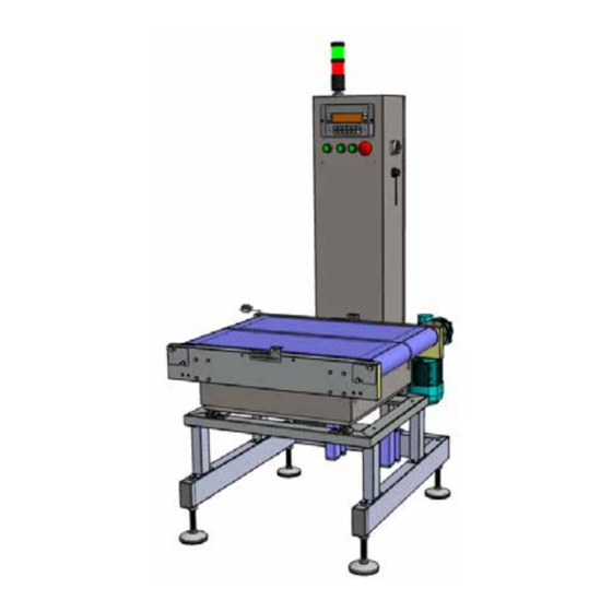
Use and warning instructions Layout measurements overall dimensions Length (a) 815 mm Width (B) 950 mm height (C) 1850 mm CHAPTER 4 - Machine description... -
Page 43: Main Components
SEL 700 Main components The machine consists of the following main parts: pos. description Frame Conveyor module Scale module Electrical panel Operator interface CHAPTER 4 - Machine description... -
Page 44: Operating Cycle
Use and warning instructions operating cycle The ejector module is composed of a metal structure carrying a conveyor belt and a piston (or air-jet) ejector. The belt conveys the product to the ejector, which - if necessary - ejects the product. The processing cycle is described in a simplified way below. -
Page 45: Transport And Installation
SEL 700 Chapter 5 TransporT and insTallaTion CHAPTER 5 - Transport and installation... - Page 46 Use and warning instructions PAGE LEFT INTENTIONALLY BLANK CHAPTER 5 - Transport and installation...
- Page 47 SEL 700 5. TransporT and insTallaTion iMporTanT! lifting and handling must be performed by skilled, trained personnel only, who are qualified to carry out these tasks. During installation, soCiETÀ CoopEraTiVa BilanCiai technicians must be assisted by the operators assigned to service and operate the machine in the future.
-
Page 48: Packaging
Use and warning instructions packaging The machine is shipped by soCiETÀ CoopEraTiVa BilanCiai from the manufacturing plant to the customer’s premises. Depending on the transport distance, the Customer’s specific requests, and the time the load remains packaged, the machine is shipped as follows: •... -
Page 49: Transport And Handling
SEL 700 Transport and handling Depending on the type of transport, soCiETÀ CoopEraTiVa BilanCiai uses suitable packaging and fixings to guarantee intactness and proper storage during transport. Upon receipt of the machine, check that no part has been damaged during transport and/or handling. if damage is found, it must be immediately notified to the Manufacturer. - Page 50 Use and warning instructions Transport with a forklift truck operator qualification Lifting and handling equipment operator required ppE lifting equipment Forklift truck Weight Based on the component to be handled CaUTion! only use suitable, approved lifting equipment, complying with the size and weight of the machine. CaUTion! Make sure that no one is standing below the operating range of the lifting device.
-
Page 51: Installation
SEL 700 installation 5.3.1 set-ups to be provided by the customer As a general rule, without prejudice to any other contractual agreements, the Customer shall be responsible for setting up: premises (including masonry, such as foundations, or any required ducts, lighting); •... -
Page 52: Installation Place
Use and warning instructions The machine is designed and built to operate safely in the following environmental conditions: permitted environmental conditions room temperature 0 - 40°C Maximum relative humidity from 10 to 85% non-condensing installation place the machine must be positioned away from vibration sources Environment lighting Neon light resting surface... -
Page 53: Positioning
SEL 700 5.3.4 positioning Before removing the packaging, place the machine in its intended place. CaUTion! The customer who manages the line and/or machine is responsible for making sure that the other pieces of equipment installed near the line comply with the standard requirements for electromagnetic emissions, so as to prevent pollution sources with values higher than normal from causing malfunctions or damaging the machine. -
Page 54: Levelling
Use and warning instructions 5.3.6 levelling To properly perform the procedure, proceed as described below: step action image Check the spirit level on the external plane of the machine. Adjust the height of the support feet by loosening the safety nut. Do/undo the screw using a wrench. -
Page 55: Sel700 + 4 I/O Terminal Installation
SEL 700 5.3.7 sEl700 + 4 i/o terminal installation All of the differences between the SEL700 terminal and the one described in the“Use and maintenance manual” for standard DD700 terminals are described below. iMporTanT! For the final users of the sEl700 terminal in the single weight version for management of a weighing line driven by the terminal itself. -
Page 56: Scale Parameters (Path: \\ Setup\ Scale\ Configurations\ General\ )
Use and warning instructions 5.3.7.1 scale parameters (path: \\ setup\ scale\ Configurations\ General\ ) Act as described below to set the scale parameters: step parameter description to prevent the scale from returning to zero which automatically deletes any stored tare Enable (recommended) “Tare lock”... - Page 57 SEL 700 step parameter description Establish whether: • the terminal must also weigh the pieces with out-of-weighing range weight (these will then be discarded through the ejector); • or momentarily stop the weighing and production, and wait for the intervention “Weight out of range, continue?”...
-
Page 58: Parameters For Input Contacts (Path: \\ Setup\ Customisations\ Outputs\ Inputs)
Use and warning instructions step parameter description Used to establish whether: The “Line start” input can also perform “Line stop”. By setting the parameter =”YES”, if the terminal is NOT running, the input will trigger the LINE START operations; “sTarT input sTarT/sTop function” however, if the terminal is running, it will trigger LINE STOP operations. - Page 59 SEL 700 step parameter description If active, the text “TRANSPORT” appears on the left of the display. When the terminal is in transport, any line start request is rejected. If the input is activated when the weighing line is active, the terminal stops the line and to be able to resume production, the operator, in addition to the activating the transport input, must manually empty the line section starting immediately after the load photocell and ending in front of the position of the ejector (this is because the emergency...
-
Page 60: Parameters For Output Contacts (Path: \\ Setup\ Customisations\ Outputs\ Output)
Use and warning instructions 5.3.7.4 parameters for output contacts (path: \\ setup\ Customisations\ outputs\ output) To set the output parameters proceed as following: step parameter description scale belt motor The scale belt must run when the output is active. active line indicator light (optional) When the weighing line is active the output is on. -
Page 61: Parameters For Analogue Output (Path: \\ Setup\ Customisations\ Outputs\ Analogue Output\)
SEL 700 step parameter description In case the transmission to PC of the “printed data string” in “single mode” and with“ack/nak protocol” is enabled. Is enabled: • upon receiving the first BEL character (or ETX character) sent by PC as an answer to the string of printed data related to the product on the scale;... - Page 62 Use and warning instructions parameter status input 01: load photocell Normally open input 02: product presence photocell Normally open input 11: downstream consent Normally open input 12: Transport or manual Normally open input 13: Emergency Normally closed input 14: line start Normally open output 01: scale motor Normally open...
-
Page 63: Data Available From User Menu
SEL 700 5.3.8 data available from user menu In addition to the data listed in the “Use and maintenance manual” for standard DD700 terminals, this terminal also provides the following data: step parameter description The parameter ranges from 0% to 100% with 1% increments: •... - Page 64 Use and warning instructions step parameter description Example: Maximum ascent time = 10 dec/sec. If at line start the selected speed % is 50%, the terminal will use a maximum upstroke time of 20 dec/sec for the process. Working times and Speed percentage are inversely proportional, namely if the speed is cut in half, the times double.
- Page 65 SEL 700 step parameter description It expresses the time it takes a piece of this product to completely transit in front of the photocell. This is both to avoid interpreting multiple openings and closings of photocells due to bounces or due to particular pieces (e.g cases rather than boxes, etc.); after the initial engagement of the photocell, its status is ignored for the entire transit time (obviously the transit time is only calculated piece Time with the belt in motion).
-
Page 66: How To Calculate The Piece Time To Associate To The Product
Use and warning instructions 5.3.8.1 How to calculate the piece time to associate to the product • Measure the length of the piece corresponding to the product in millimetres; • establish how many m/sec a line speed of 100% corresponds to. Called: Lpiece the length in mm Vline the line speed in m/sec... -
Page 67: Main Page
SEL 700 5.3.9 Main page The terminal shows this page at start up and ‘exits’ this page only after the intervention of an operator: • pressing the “2°F” hotkey; • pressing the “START” hotkey; • “Line start” input activation to start production. 5.3.9.1 data displayed on main page The display is mostly engaged by the weight present on the scale together with all of its metrological messages. - Page 68 Use and warning instructions • “CMERC”: this is the key that allows you to view and/or set the product code both for any entry or editing in the product codes archive, and to select the product to send for processing. •...
-
Page 69: Working Page
SEL 700 5.3.10 Working page The terminal shows this page after accepting a line Start request and ‘exits’ this page automatically after a weighing operation ended with an error: • which requires the intervention of an operator; • or due to a direct intervention of the operator who pressed the “STOP” hotkey or because they activated the “EMERGENCY” input;... -
Page 70: Weight Printout And Transmission To Pc (Optional)
Use and warning instructions the above-mentioned threshold, the stop command remains in progress and the operator needs to intervene by pressing the emergency pushbutton. • “EMERGENCY”: this is the input which when activated places the terminal in emergency status; the weighing line is deactivated and the terminal goes back to the “home page”. - Page 71 SEL 700 a line is added at the bottom of the printout reading “DATA NOT TRANSMITTED”; if the transmission finishes with a failure only because the PC rejected the piece, the weighing operation continues and a line is added at the bottom of the printout reading “NONCONFORMING PIECE”.
-
Page 72: Additional Transmission Parameters
Use and warning instructions NOTE If the archive cannot be completely emptied with the last weighing of the work shift or day, it is possible to do so without carrying out an additional weighing operation. In fact, it is sufficient for the PC to send the ENQ character (05 hexadecimal) to the terminal and the archive will be emptied by temporarily adopting the transmission mode “Archive”. -
Page 73: Calculating The Checksum
SEL 700 If the string is received correctly, the PC must send, within a time defined in seconds during installation, a single character: ACK (06Hex). If the “printed data string” was enabled in “single mode”, the ack/nak protocol can also manage the character BEL (07Hex): the PC must send the character BEL, within the time (in seconds) defined during installation, when it received the data string correctly but is not yet capable of authorising the weighing operation. -
Page 74: Important Notes And Limits Of The Terminal
Use and warning instructions If in the double weighing mode, you can only save outgoing weighing OUTGOING processes. Save weighing processes If in the double weighing mode, you can save both incoming and ALWAYS outgoing weighing processes. The data string saved in the CSV format contains the same data of the "printed data string" in serial (see the advanced operating manual), but with fields separated with ";". -
Page 75: Error Messages And Warnings
SEL 700 step action The load belt starts to run and the first piece reaches the load photocell also starting the scale belt. The first piece continues on its way until it arrives in front of the piece presence photocell, thus stopping the scale belt to be able to perform the weighing operation. - Page 76 Use and warning instructions weight higher than zero and net weight in scale already higher than minimum net): the request is rejected. product code missing A Line start request was made with the selected product code equal to zero or not present in product codes archive: the request is rejected.
-
Page 77: Connections
SEL 700 Connections To start the machine, the necessary connections to the local mains must be ensured: • electrical connection (including earthing connection), in compliance with the regulations in force in the country of installation. Guaranteeing the required connection characteristics is the user’s responsibility. CaUTion! The required connections must be made by qualified and authorised personnel. - Page 78 Use and warning instructions PAGE LEFT INTENTIONALLY BLANK 5-34 CHAPTER 5 - Transport and installation...
-
Page 79: Controls And How To Use Them
SEL 700 Chapter 6 Controls and how to use them CHAPTER 6 - Controls and how to use them... - Page 80 Use and warning instructions PAGE LEFT INTENTIONALLY BLANK CHAPTER 6 - Controls and how to use them...
-
Page 81: Operator Workstation
SEL 700 6. Controls and how to use them During operation, the machine requires to be manned continuously by an operator. For all the control procedures and on/off modes, see the use and maintenance manual for the main machine. attentIon! using the machine for a purpose other than that envisaged by the manufacturer could cause severe damage to people and/or things and/or animals. -
Page 82: Command Pushbutton Panel
Use and warning instructions Command pushbutton panel The buttons of the pushbutton panel are described below. Pos. element description Operator panel (See paragraph 6.3) Bypass selector Deactivates the weighing function to allow the products to pass without check START button Activates the machine operating cycle Power supply Indicates that the machine is powered... -
Page 83: Operator Panel
SEL 700 operator panel The machine is intended to be controlled by an operator through an operator interface with all the controls required to run and control the machine. For information on the operation of the operator panel, please refer to the attached documentation. CHAPTER 6 - Controls and how to use them... -
Page 84: Operational Procedures
Use and warning instructions operational procedures 6.4.1 Preliminary checks The following checks must be carried out before commissioning the machine. • Check that the machine is standing on a surface that can support its weight. • Check the operation of the safety devices. •... -
Page 85: Restart After An Emergency Stop
SEL 700 6.4.4 restart after an emergency stop Follow the procedure below to restart the machine after an emergency stop: step action Find and eliminate the cause of the machine emergency stop. Check to make sure that there is no one inside the dangerous area of the machine. Reset the emergency pushbutton that has been pressed. - Page 86 Use and warning instructions PAGE LEFT INTENTIONALLY BLANK CHAPTER 6 - Controls and how to use them...
-
Page 87: Maintenance
SEL 700 Chapter 7 MaintenanCe CHAPTER 7 - Maintenance... - Page 88 Use and warning instructions PAGE LEFT INTENTIONALLY BLANK CHAPTER 7 - Maintenance...
- Page 89 SEL 700 7. MaintenanCe CaUtiOn! Perform maintenance work when the machine is off (main switch set to “0”- “OFF”). CaUtiOn! Maintenance work must be performed by qualified, authorised personnel. Servicing the machine includes performing the operations (inspections, examinations, checks, adjustments and replacements) that are required after normal use.
-
Page 90: Safety Warnings
Use and warning instructions Safety warnings CaUtiOn! Before starting any maintenance work on the machine, disconnect and padlock all energy sources, and put the moving units that comprise it in a safe lock condition. Place a “Machine under maintenance - do not switch on” sign close to the main switch. -
Page 91: Routine Maintenance
SEL 700 Routine maintenance When the machine is delivered to the user, it is already adjusted to work properly; however, to ensure its proper operation over time, periodic and preventive checks as well as maintenance work must be carried out. Routine maintenance includes inspections, checks and operations which, to prevent failures, keep the following under control: •... -
Page 92: Replacing The Conveyor Belt
Use and warning instructions 7.2.1.1 Replacing the conveyor belt Operator qualification Mechanical maintenance technician Required PPe tools to be used Manual tools To replace the conveyor belt, proceed as described below: Step action image Switch off the machine and disconnect it from the mains. Remove the 4 front (pos.1) and side (pos.2) protective guards. - Page 93 SEL 700 Step action image Fit the new elastic belt and proceed with tensioning. Refit the front panel of the belt. Refit the front and side protective guards. CHAPTER 7 - Maintenance...
-
Page 94: Conveyor Belt Tensioning
Use and warning instructions 7.2.1.2 Conveyor belt tensioning Operator qualification Mechanical maintenance technician Required PPe tools to be used Manual tools CaUtiOn! Do not tension the belts more than necessary since it reduces its service life and increases wearing of the driving system. -
Page 95: How To Check The Weighing System
SEL 700 7.2.1.3 How to check the weighing system iMPORtant! Contact the Manufacturer's after-sales Service if the tests are beyond the tolerated error margin. iMPORtant! never attempt to tamper with the weighing system or its parts. iMPORtant! Removal of the seals will immediately void the approval of the system and the warranty provided by the manufacturer. -
Page 96: Cleaning
Use and warning instructions 7.2.2 Cleaning CaUtiOn! Cleaning operations must be performed by qualified, authorised personnel only. CaUtiOn! adhere to the wash water treatment regulations in force in the country of installation. Frequency Operation Daily Weekly Monthly Half-yearly Yearly ◈ Cleaning conveyor belts ◈... -
Page 97: Cleaning Photocells
SEL 700 7.2.2.2 Cleaning photocells To clean photocells, proceed as described below: Step action Disconnect the machine from the electricity mains. Use a cotton cloth moistened with alcohol. Carefully clean the photocell lenses. Also clean the reflector in front of the photocell. Dry with a dry cloth. -
Page 98: Extraordinary Maintenance
Use and warning instructions extraordinary maintenance CaUtiOn! extraordinary maintenance and repair work may be performed on the machine by qualified, instructed and authorised technicians only, employed by the Manufacturer or an authorised service centre. this type of work requires in-depth, specific knowledge of the machines, necessary operations, associated risks and proper procedures to operate safely. -
Page 99: Decommissioning And Disposal
SEL 700 Chapter 8 DeCommissioning anD Disposal CHAPTER 8 - Decommissioning and disposal... - Page 100 Use and warning instructions PAGE LEFT INTENTIONALLY BLANK CHAPTER 8 - Decommissioning and disposal...
-
Page 101: Disposal
SEL 700 8. DeCommissioning anD Disposal CaUTion! Decommissioning and dismantling must be entrusted to personnel specialised in performing these activities. in particular, only the person in charge of dismantling and end-of-life disposal may: mechanically and electrically disconnect parts according to disassembly instructions and project plans. •... - Page 102 Use and warning instructions PAGE LEFT INTENTIONALLY BLANK CHAPTER 8 - Decommissioning and disposal...
- Page 103 PNEUMATIC EJECTOR Chapter 9 ANNEXES CHAPTER 9 - Annexes...
- Page 104 Use and warning instructions PAGE LEFT INTENTIONALLY BLANK CHAPTER 9 - Annexes...
-
Page 105: Annexes
PNEUMATIC EJECTOR 9. ANNEXES This chapter contains the documentation annexed to the machine. The annexed documentation is an integral part of the “INSTRUCTION, USE AND MAINTENANCE MANUAL” of the machine supplied by SOCIETA’ COOPERATIVA BILANCIAI and must be referred to when using, operating and servicing the equipment and its components. - Page 106 Use and warning instructions PAGE LEFT INTENTIONALLY BLANK CHAPTER 9 - Annexes...
- Page 108 Soc. Coop. Bilanciai Campogalliano Campogalliano (MO) - 41011 - Via S.Ferrari, 16 Tel. +39 059.893611 info@coopbilanciai.it - www.coopbilanciai.com...
Need help?
Do you have a question about the BILANCIAI SEL700 and is the answer not in the manual?
Questions and answers