
Summary of Contents for ALP EV EASY CHARGE DUO-AC22 Series
- Page 1 ALP EV EASY CHARGE DUO Installatie handleiding Link naar ALP EV CHARGING APP: https://alp-ev-charging-50647.web.app/#/...
-
Page 2: Table Of Contents
CONTENTS SAFETY INFORMATION ......................2 SAFETY WARNINGS ......................2 GROUND CONNECTION WARNINGS ..................3 POWER CABLES, PLUGS and CHARGING CABLE WARNINGS ............3 WALL MOUNTING WARNINGS ....................3 MODEL DESCRIPTION ......................4 GENERAL INFORMATION ......................5 INTRODUCTION OF THE PRODUCT COMPONENTS ..............5 DIMENSIONAL DRAWINGS.......................5 TECHNICAL SPECIFICATIONS....................6 CONNECTIVITY ........................ -
Page 3: Safety Information
heating sources, may cause reduction of charging SAFETY INFORMATION current or temporary interruption of charging process. • The charging station is intended for outdoor and CAUTION indoor use. It can also be used in public places. • To reduce the risk of fire, electric shock or product RISK OF ELECTRIC damage, do not expose this unit to severe rain, SHOCK... -
Page 4: Ground Connection Warnings
• Defects and damage that occur during has broken insulation, or shows any other signs transportation after the delivery of the product of damage. to the customer are not covered by the warranty. • Ensure that the charging cable is well positioned •... -
Page 5: Model Description
MODEL DESCRIPTION MODEL DESCRIPTION: Alp Easy Charge Duo-AC**-* Alp Easy Charge Duo : Electric Vehicle AC Charger (Mechanical Cabinet 10) 1st Asterisk (*) : Rated Power 14* : 2*7.4 kW (1Phase Supply Equipment) 22* : 2*11 kW (3Phase Supply Equipment) 44* : 2*22 kW (3Phase Supply Equipment) 2nd Asterisk (*) can include combinations of the following communication module options. -
Page 6: General Information
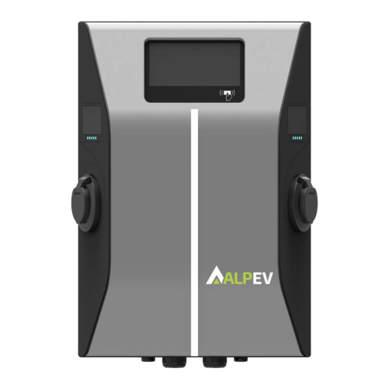
GENERAL INFORMATION INTRODUCTION OF THE PRODUCT COMPONENTS Alp Easy Charge Duo Models Information Display RFID Card Reader MID Meter Windows Indicator LED Socket Outlets Illumination LED DIMENSIONAL DRAWINGS © 2023 ZES - Tüm hakları saklıdır English - 5... -
Page 7: Technical Specifications
TECHNICAL SPECIFICATIONS This product is compliant to IEC61851-1 (Ed3.0) standard for Mode 3 use. Model Alp Easy Charge Duo-AC22 Series IEC Protection class Class - I Cable Model 2 x Cable with TYPE 2 ( IEC 62196) Female Plug Voltage and Current Rates... -
Page 8: Environmental Technical Specifications
ENVIRONMENTAL TECHNICAL SPECIFICATIONS Protection Class Ingress Protection IP54 Impact Protection IK10 Usage Conditions Temperature -25 °C to 50 °C (without direct sunlight) Humidity 5% - 95% (relative humidity, without condensation) Altitude 0 - 4,000m OTHER FEATURES (Connected Models) Potential Free Enable Input Signal input for controlling the charging station externally Welded Contactor Indication 230V AC output for shunt trip in case of welded contacts... -
Page 9: Required Equipment, Tools And Accessories
REQUIRED EQUIPMENT, TOOLS and ACCESSORIES Drill Bit 8mm Impact Drill Torx T20 Security Volt Indicator Water Level Screwdriver Flathead Screwdriver Right Angle Screwdriver Adapter (Tip width 2.00-2.5 Hexagon Key / Torx T20 Security Bit Cat5e or cat6 RJ45 Crimping Tool ethernet cable ©... -
Page 10: Installing Charging Station
INSTALLING CHARGING STATION BOX CONTENTS FOR CHARGING STATION SUPPLIED INSTALLATION EQUIPMENT and ACCESSORIES Accessory/Material Use For Quantity Picture Name Dowels (M8x50 Plastic Mounting charging station to the wall Dowels) Torx T25 Security Screw Mounting charging station to the wall (M6x75) Torx T20 Security IP for screws which are used for L-Wrench... -
Page 11: Product Installation Steps
User RFID Card Start&Stop Charging Adding&Removing the User RFID Cards to Master RFID Card Local RFID List 1 Set Installation Guide Installation Manual 1 Set Instruction Book User Manual PRODUCT INSTALLATION STEPS CAUTION! • Ensure that ground resistance of the installation is less than 100Ω. •... -
Page 12: Opening And Closing The Front Cover Of The Charging Station
OPENING AND CLOSING THE FRONT COVER OF THE CHARGING STATION CAUTION RISK OF ELECTRIC SHOCK Please power off the charging station mains supply Remove the cover screws with Torx T20 security L-Wrench or Right Angle Screwdriver Adapter using Torx T20 Security Bit. - Page 13 After the operation is finished, position the front cover's top part over the top part of the back cover via attaching the hooks. While the hooks of the front cover are hanging, reconnect the LED cables of the unit as shown in figure. Before closing the front cover, make sure that the seal of the back cover is applied properly and LED cables are not stuck in between the front/back cover.
-
Page 14: Wall Mount Installation
WALL MOUNT INSTALLATION Wall mount installation is common for all charging station models. Open the product front cover by following the instruction as mentioned in section "OPENING AND CLOSING THE FRONT COVER OF THE CHARGING STATION". Place the template which is given in accessory bag and mark the drill bit holes with a pencil. Drill the wall on the marked points using the impact drill (8mm drill bit). - Page 15 Data AC Mains Wrench Cable Cable Before closing the cover of the charging station, check next instructions if any function related to these sections are used. © 2023 ZES - Tüm hakları saklıdır English - 14...
-
Page 16: Three Phase Charging Station Ac Mains Connection
THREE PHASE CHARGING STATION AC MAINS CONNECTION Insert the cables to the terminal block as shown in the image. Check the table below to match Electric Terminal number with AC Cable Color. Press the button on the terminals via a screw driver or a similar tool to be able to insert and remove the cables. -
Page 17: Data Cable Connection
DATA CABLE CONNECTION Remove rubber cork from cable gland. Follow the instructions below. Insert cable through the cable gland. Pull the cable through the cable clamps as indicated by arrows in below figure. Using a Crimping Tool, trim the end of the cable Strip off approximately 1 inch of the cable’s you’re terminating, to ensure that the ends of the jacket, using a modular crimping tool or a UTP... - Page 18 Carefully insert the flattened, arranged wires Check to make sure that the wire ends coming into the connector, pushing through until the wire out of the connector’s pin side are in the correct ends emerge from the pins. order. If you realize that a mistake has been made in wire order after termination, you’ll have to cut the connector off and start all over again! Insert the prepared connector/cable assembly...
- Page 19 Finally, to connect the wires on mainboard, check next sections depending on the function(s) to be used. NOTE: Below data connection cables can be inserted through the cable holes; External enable input cable Power optimizer measurement cable Load shedding triggering signal cable Shunt trip module control signal cable for welded relay contact failure ©...
-
Page 20: Adjusting Current Limiter
ADJUSTING CURRENT LIMITER The charging station has the ability to set the power of the unit with the current limiter setting in the WEB Configuration Interface. This menu is used to set the current and power of the charging station. As shown in the figure below, after selecting the current limiter phase, the current limiter value can be specified at the bottom of the current. - Page 21 EXTERNAL ENABLE INPUT FUNCTIONALITY Your charging station has external potential free enable / disable functionality which can be used for integration of your charging station to carpark automation systems, energy supplier ripple control devices, time switches, photovoltaic inverters, auxiliary load control switches, external key lock switches etc. You can enable/disable it from the WEB Configuration interface as shown in the image below.
- Page 22 EN1S Cable Terminal Cable Color 1 (EN1) Green 2 (EN1S) Green + White Green © 2023 ZES - Tüm hakları saklıdır English - 21...
-
Page 23: Locked Cable Function (Model With Socket)
LOCKED CABLE FUNCTION (Model With Socket) The cable becomes locked and your socket model charging station starts behaving as an attached cable model. To enable locked cable function you need to access to WEB Configuration Interface and Enable the part "Lockable Cable"... -
Page 24: Power Optimizer (Requires Optional Accessories)
POWER OPTIMIZER (REQUIRES OPTIONAL ACCESSORIES) This feature is provided with an optional metering accessories which are sold separately. In power optimizer mode, the total current drawn from the main switch of the house by charging station and other household appliances is measured with current sensor integrated to the main power line. Current limit of the main power line of the system is set through the DIP switches inside the charging station. - Page 25 RCCB MCBs Power Optimizer Meter Main Switch Household Appliances RCCB Grid Utility Meter Communication (ModBUS) Alp Easy Charge Duo Power Optimizer Meter should be placed just after the main switch of the house as shown in the figure below Power Optimizer Meter wiring connections can be made according to the information below. Three Phase Single Phase 22-23: A-B (COM) Modbus connection over RS485 for three phase charging station models.
- Page 26 Cable Terminal Cable Color Description (CN69-2) Green A (COM) (22 3P MID, 10 1P MID) (CN69-1) Blue B (COM) (23 3P MID, 11 1P MID) © 2023 ZES - Tüm hakları saklıdır English - 25...
-
Page 27: Mode Selection Switch Settings
MODE SELECTION SWITCH SETTINGS This charging station has 3 operation modes. For standard charging the mode selection should be in position 1. • Operation Mode 1 (Standard Charging): This mode is factory default configuration. When this mode is selected, charging station does not support peak/off peak time or TIC dynamic charging scenarios. •... -
Page 28: Load Shedding
LOAD SHEDDING This charging station supports load shedding functionality which provides immediate charging current reduction in case of limited supply. Load shedding functionality can be used in any mode including Standalone and OCPP connected modes. Load shedding triggering signal is a dry contact signal which must be provided externally and connected to the terminals 3 and 4 on the power board as shown in figure below. -
Page 29: Monitoring Of Welded Relay Contacts Failure
MONITORING OF WELDED RELAY CONTACTS FAILURE According to IEC 61851-1 and EV/ZE Ready requirements, EVC04 EV Charging Station has welded contactor sensing function and in case of welded contact occurs, shunt trip 230V signal is provided from the main board. To detect welded contact failure for the relays, CN33 connector output terminals must be used. In case of a welded contact for the relays CN33 connector output will be 230V AC. -
Page 30: Factory Reset
FACTORY RESET To return to the factory settings, you must press the SW5 button on the ACPW card shown in the figure below. When you hold the button for 5 seconds user configuration will be reset to factory configuration. (e.g OCPP config, Network Config will be back to factory configuration.) SETTING ETHERNET PORT OF CHARGER TO STATIC IP IN STANDALONE USAGE MODE... -
Page 31: Web Configuration Interface Enable / Disable
Toggle If the charger’s LAN interface is needed to be set back to DHCP mode again this can be done from the web configuration interface. Note: You can also use factory reset function to set the LAN interface back to DHCP mode again but please well note that all other parameters will be set to factory default parameters. -
Page 32: Ocpp Connection
OCPP CONNECTION Make sure the charging station is powered-off. CONNECT OCPP OVER CELLULAR NETWORK Insert the micro SIM card into the SIM card slot on the cellular module as shown in the figure below. The orientation of the SIM card should be such that the notch is to the left. COMMISSIONING If you want to connect the charging station’s web configuration interface, you have two options;... - Page 33 • Standalone mode settings • Local Load Management: Load Management Option • System Maintanence: • Log Files,Firmware Updates,Configuration BackUp&ResWebconfig UI v2tore,System Reset,Administration Password,Factory Default Configuration © 2023 ZES - Tüm hakları saklıdır English - 32...
-
Page 34: Connect Pc To The Same Network With Smart Board
CONNECT PC TO THE SAME NETWORK WITH SMART BOARD In order to access WEB Configuration Interface, first you need to connect your PC and EV charger to the same ethernet switch or connect EV charger to your PC directly. Default IP address of HMI board is 192.168.0.10. For this reason, you need to give static IP to your PC in the same network with HMI board. -
Page 35: Opening Web Configuration Interface Via Wifi Hotspot
New password must contain at least 1 lowercase letter, 1 uppercase letter, 1 numeric character and minimum 6 characters. After typing your current password and new password twice, you will be redirected to the login page once more to log in with your new password. All spaces you will see are mandatory in this page. -
Page 36: Web Configuration Interface
Note: Maximum 3 users can connect to WEB Configuration Interface via Wi-Fi hotspot. It supports 2.4Ghz. WEB CONFIGURATION INTERFACE After the successful login operation, you are directed to the main page. Main page shows the general information about the device that are user name, software versions,connection interface and ids. - Page 37 In this part, you can select Current Limiter Settings from Web configuration. Current Limiter User can select Current Limiter Phase, options are One Phase or Three Phase. Settings Current Limiter Value can take value between 6 and 32. In this part, you can select Unbalanced Load Detection from Web configuration. Options are Disabled and Enabled.
- Page 38 CHANGE OCPP SETTINGS OF THE DEVICE If you select mode as "Enabled"; you should type all fields in the connection settings and configuration parameters sections are enable in the below. For now, the only available OCPP version is OCPP 1.6, so it will be selected as default.
- Page 39 LOCAL LOAD MANAGEMENT PAGE If the device without dynamic local load management; local management option can be disabled or modbus TCP. If the device with dynamic local load management; local management option can be disabled, modbus TCP or Master/Slave. If Load Management Option is selected as Master/Slave, there will be two part in this page; General Settings and Load Management Group.
-
Page 40: Wireless Lan Transmitter Specifications
MAKING SYSTEM MAINTANENCE OF THE DEVICE You can download OCPP or HMI logs by clicking buttons. Download log files In LOG FILES Page will be shown after a few seconds. In FIRMWIRE You can upload only zip files. After choosing the file you can carry out firmware UPDATE Page update. - Page 41 © 2023 ZES - Tüm hakları saklıdır English - 40...
- Page 42 © 2023 ZES - Tüm hakları saklıdır English - 41...
Need help?
Do you have a question about the EASY CHARGE DUO-AC22 Series and is the answer not in the manual?
Questions and answers