Advertisement
Quick Links
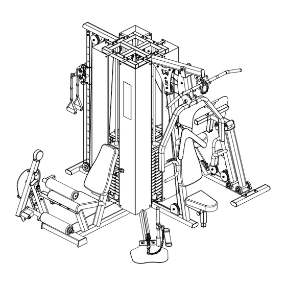
MS-54 Multi station
Metagenics Fitness Inc.
MS-54 Multi station
FM440P/S
FOUR WEIGHT
WORK STATION
The company reserves the right to interpret and correct printing errors in
the manual. Data changes due to product upgrades and improvements
will not be notified without prior notice, and the changed content will be
directly incorporated into the new version of the manual.
Advertisement

Summary of Contents for Metagenics Fitness MS-54
- Page 1 MS-54 Multi station Metagenics Fitness Inc. MS-54 Multi station FM440P/S FOUR WEIGHT WORK STATION The company reserves the right to interpret and correct printing errors in the manual. Data changes due to product upgrades and improvements will not be notified without prior notice, and the changed content will be ...
-
Page 3: Points For Attention
POINTS FOR ATTENTION 1.This equipment should be installed and used on a firm, flat and clean ground, not close to areas with water, nor can it be used outdoors. There should be a safety area of a t least 1 meter around the equipment, and objects with edges and corners that may hurt people shouldn't be placed around the equipment. - Page 4 POINTS FOR ATTENTION 9.Don't push too hard or get too tired. Please choose the weight stacks reasonably and avoid using too heavy weight stacks, otherwise it may cause injury. Incorrect exercise and overtraining can cause harm to human health. 10. Never allow any objects to fall into or be inserted into any openings in the equipment.
- Page 5 Packing List F×8 A×1 B×1 G×8 E×4 C×4 D×8 K×1 H×1 (1#Steel cable pre-installed) J×1 L×1 M×3 O×1 R×1 N×1 V×1 I×1 S×1...
- Page 6 Packing List T×1 X×7 AZ×1 U×1 AA×1 Y×1 Z×1 AC×1 AE×1 AD×1 AB×1 AI×2 AM×1 AK×1 AL×1 AN×1 AJ×1...
- Page 7 Packing List AO×1 AP×1 AS×1 AT×1 AV×1 AX×2 AY×2 AW×2 AU×1 BD×1 BE×2 BG×4 BF×56 BH×4...
- Page 8 Packing List BJ×3 BI×1 BK×8 BL×8 skin packaging BM×1套 Q.2×1 AG.3×1 AH.4×1 AQ.5×1 AR.6×1 BB.8×1 BC.9×1 BA.7×1...
- Page 9 STEP1 NOTICE NAME ITEM 1. It is recommended that two or more people install together, otherwise it is prone to danger. Top seat on the center bucket 2. Read this manual carefully before installation. Installation according to this Center bucket under the base manual steps can speed up the installation speed and avoid installation errors.
- Page 10 STEP2 1. Use the bolt (a1) 4 to connect the top frame (h) with the main NAME ITEM frame (i) with the central barrel, and the pre-installed steel cable of CHEST PRESS TOP FRAME the top frame passes through the large hole of the central barrel. CHEST PRESS UPRIGHT FRAME 2.
- Page 11 STEP3 1. Connect the chest bearing cushion (l) to the rack with bolts (a1) ITEM NAME SEAT PAD 2. Connect the bolts (a6) 2 to the general back cushion (m) to the rack BACK PAD M10×25BOLT,SHCS M10×60BOLT,SHCS M10 FLAR ×2 a6 b1 ×2 a1 b1...
- Page 12 STPE4 ITEM NAME Tighten the four set AXLE screws after installtion ASSY 1. Install the thrust arm (j), push the auxiliary shaft (k) through the sleeve, and the lock tightly sets the screw.
- Page 13 STEP5 ITEM NAME CABLE1# L: 4590mm 1#CABLE ASSY,FLOATING DUO PULLEY 1. Install the 1 # steel cable (P), bypass the double pulley frame (AZ), and reach the counterweight top pressing plate. Ensure that the steel cable passes under the shaft...
- Page 14 STEP6 Split Kick a1 b1 ×2 ×2 d1 b1 ×2 a3 b1 1. Use bolts (a1) × Connect the bottom pipe (N) in the ITEM NAME fifth direction to the center barrel with bolts (a3) × 2. LOW PULLEY Connect the fifth directional pedal (O) and the fifth LOW PULLEY FOOT PLATE directional bottom pipe (N) M10×25 BOLT,SHCS...
- Page 15 STPE7 ITEM NAME 2#CABLE 1. Install the 2 # steel cable (Q) as shown in the figure, and disassemble the end assembly of the steel cable during installation, which helps to quickly install the steel cable. CABLE2# L: 6390mm...
- Page 16 STPE8 ITEM NAME LEG STATION MAIN FRAME LEG STATION SIDE FRAME LEG STATION LINKAGE M10×25 BOLT,SHCS M10×70 BOLT,SHCS M10×75 BOLT,SHCS M10 FLAT M10 LOCK LOCK NUT M10 1. Use bolts (a1) as shown in the figure to connect the main frame (Y) of the kick orientation and the central barrel, and use bolts (a1) to connect the main frame (Y) of the kick orientation and the auxiliary support of the kick orientation Frame (Z).
- Page 17 STEP9 1. As shown in the figure, the turntable (AE) passes through the ITEM NAME holes of the kick tube (AB) and the main frame of the kick ADJUSTMENT ARM orientation, and is fixed with an aluminum alloy hoop (AF). LEG PRESSURE TUBE ANKLE PAD FRAME 2.
- Page 18 STEP10 ITEM NAME 3#CABLE 4#CABLE 3.5IN FLOATING PULLEY CABLE3# L: 2445mm CABLE4# L: 3090mm...
- Page 19 STEP11 1. Connect the leg connection pipe (AL) to the center barrel ITEM NAME with bolts (a1) as shown in the figure LEG PRESS MAIN FRAME 2. Use bolts (a3) to connect the pedal leg connecting tube (AL) LEG PRESS FRONT FRAME ...
- Page 20 STEP12 1. Use bolts (a5) as shown in the figure to connect the main ITEM NAME frame of the pedal position to the pedal (AN) of the pedal LEG PRESS PLATE SEAT PAD 2. Use bolts (a2) to connect the pedal seat cushion (AO) to the BACK PAD pedal orientation main frame M10×75 BOLT,SHCS...
- Page 21 STEP13 CABLE5# L: 2230mm NAME ITEM 5#CABLE 6#CABLE CABLE6# L: 2990mm 3.5IN FLOATING PULLEY...
- Page 22 STEP14 NAME NAME ITEM ITEM M10×65 BOLT,SHCS CABLE COLUMN TOP FRAME CABLE COLUMN BOTTOM FRAME M10×50 BOLT,SHCS COLUMN M10×25 BOLT,SHCS M10 FLAT PULLEY HOUSING M10 SPRING PAD 4.5IN PULLEY LOCK NUT M10 PULLEY COLUMN CABLE RETAINER BRACKET ×2 a8 b1...
- Page 23 STEP15 ITEM NAME CABLE7# L:3470mm 7#CABLE 8#CABLE 9#CABLE CABLE8# L: 7400mm 4.5IN PULLEY HANDLE,NYLON STRAP CHAIN CABLE9# L: 1790mm 1. Install the 7 #, 8 #, and 9 # steel cables as shown in the figure. 2. Steel cable 9 # is a limiting steel cable to prevent pulley rotation, which passes through the hole on the 4.5 inch BB BC suspension pulley frame (BD) during installation...
- Page 24 STEP16 1. Install the counterweight block. During installation, remove ITEM NAME the top bolt of the guide rod and remove the top pressure 5KG WEIGHT PLATE plate from the guide rod. NUMBER STICKER 2. Slide the counterweight block along the guide rod, with 14 counterweight pieces (BF) in each group M10×170 BOLT,SHCS ...
- Page 25 STEP17 NAME ITEM NAME ITEM FRONT SHROUD M10×70 BOLT,SHCS REAR SHROUD M6×15 BOLT,SHCS TOP SHROUD HOLDER M10 FLAT BOTTOM SHROUD HOLDER M6 FLAT TRAINING DIAGRAM LOCK NUT,M10 a2 b1 x8 BK x2 b1 d1 x8 BJ x3 Pay attention to the direction of the gap a10 b3 x32...
- Page 26 STEP18 NAME ITEM Straight pull rod Chain 18 sections Triangle shoulder strap Ankle joint band High tension rod Chain 8 sections Splay buckle...
- Page 27 WARM UP GUIDE Tips: Warm up exercise can make the body in a proper state of exercise, improve the toughness of muscles and ligaments, lubricate joints, reduce the probability of sports injuries, and prevent cramps, sprains and other problems. 1.Calf muscle stretching Standing near the wall, the left foot is about 45cm away from the wall, and the right foot is about 30cm behind the left foot.
-
Page 28: Maintenance
MAINTENANCE 1.Check whether the screws and bolts are loose. -Check whether the screws and bolts are loose and inspect them for damage such as cracks, bad threads, corrosion or rust. Fasteners may loosen during normal use. Check all nuts, bolts, screws and other fasteners to ensure they are tight and installed correctly. - Page 29 MAINTENANCE -In addition to checking for damage to the wire ropes and end connections, make sure each wire rope is properly adjusted and secured on top of the weight stacks. Check rope pulleys, end connections and end fittings to ensure all connections are secure, adjust rope tension as needed. Make sure that the wire rope bolt has at least 15mm connect to the selector rod or spherical plain bearing, and that the lock nut is tightened.
- Page 30 MAINTENANCE 8.Inspect and lubricate bearings and bushings -Inspect copper bushings, straight bushings or nylon bushings for excessive wear or damage, and replace as soon as possible if damaged. If the surface of the guide rod is rusted, use high-quality steel wool for polishing. -A small amount of silicone spray lubricant is recommended to lubricate these sleeves that often support the rotating shaft.
- Page 31 MAINTENANCE 12.Lubricate the spring pin -Pull the ejector pin to its limit and spray a small amount of silicone oil spray. Wipe off any excess lubricant with a cloth. Note: Pulling the ejector pin may cause the device to change position suddenly. To avoid injury, keep your hands and head away from moving parts.
Need help?
Do you have a question about the MS-54 and is the answer not in the manual?
Questions and answers