
Related Manuals for DAYLIFF DSmart300


Summary of Contents for DAYLIFF DSmart300
- Page 1 DSmart Smart Water Boosting System DSmart300/500 DSmart750 DSmart1500 Installation & Operating Manual...
- Page 2 INDEX PUMP SPECIFICATIONS 2. SYMBOLS & WARNINGS INSTALLATION OPERATION MAINTENANCE TROUBLE SHOOTING WARRANTY © Davis & Shirtliff Ltd 2023 Contents herein are not warranted...
-
Page 3: Pump Specifications
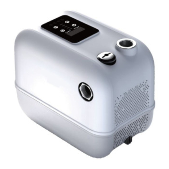
Congratulations on selecting a Dayliff DSmart Pump. They are manufactured to the highest standards and if installed and operated correctly will give many years of efcient and trouble free service. Careful reading of this Installation Manual is therefore important and any queries should be referred to the equipment supplier. - Page 4 PUMPS DAYLIFF DSmart Pumps are innovative centrifugal self-priming variable speed automatic water boosting systems for pressurised water supply, variable speed technology providing constant pressure at varying water demand levels. Pump construction is engineering plastic throughout except DSmart750 which has stainless steel pump body with external casings made from UV proof components suitable for indoor and outdoor installations.
-
Page 5: Symbols And Warnings
PUMP DATA Inlet/ Motor Dimensions (mm) Weight Current Inlet/Outlet Outlet Model (kW) (kg) Pressure (Bar) (”) DSmart300 DSmart500 DSmart750 0.75 DSmart1500 13.1 Outlet Outlet Outlet Inlet Inlet Inlet DSmart300/500 Dsmart750 DSmart1500 2. SYMBOLS AND WARNINGS Before commencing installation ensure equipment is well protected and the power supply has been switched off. -
Page 6: Installation
3. INSTALLATION Inspecting the product Ÿ Check pump’s voltage and frequency of the product match the voltage and frequency of the installation site. DSmart 300/500 Material Part Name Material Part Name Waterproof Screw Nylon 66 Screw Fan Cover Check Valve Nylon Hull Plastic... - Page 7 DSmart 750 Material Part Name Material Part Name Hull PC+PBT Fan Cover PC+PBT Water Inlet Guide Glade PPO-GF30 PP-GF10 Capacitor Box ABS (VO) PPO-GF30 Guide Glade Impeller PPO-GF30 Gland Prop PA6-GF30 Controller P .C Board Copper Coil Radiation Fin Stator Seal Holder PPO-GF30 Overhead Tank...
- Page 8 DSmart 1500 Material Part Name Material Part Name 45#Nickel Bolt Rotor 06Cr19Ni10+45# plating Check Valve HPb59-1 Motor 50WW600 Drain Plug HPb59-1 Pump Body 06Cr19Ni10 Fan Cover Bearing Gland Return Valve HPb59-1 Controller Water Inlet Guide Glade 06Cr19Ni10 Panel Guide Glade 06Cr19Ni10 Gland Silica...
- Page 9 The pump can be installed indoors or outdoors. WARNING For emergencies and maintenance, the pump must be easily accessible. WARNING The pumps must be installed in a dry position and protected from the elements by means of a suitable cover. WARNING As advised on dimensions table, enough space for service and maintenance access should be considered.
-
Page 10: Pipe Connection
Pipe Connection Ÿ To prime pump, add water to the priming plug until it overflows. Ÿ When installing the water pump, avoid use of soft rubber pipe, due to risk of collapsing. Ÿ The foot valve shall be vertical and installed 30cm away from the bottom of the water to avoid drawing in of sediments. -
Page 11: Installation Examples
Installation Examples Higher Floor Tank Higher Floor Roof Tank Lower Floor Lower Floor Ground Higher Floor Tank Higher Floor Roof Tap Water Well Foot Valve Ground... -
Page 12: Operation
4. OPERATION Priming the pump To start the pump, it is necessary to prime it by filling with water. Do not start the pump until it has been filled with water. Ÿ Unscrew the priming plug and allow an even flow of water. Ÿ... -
Page 13: Control Panel
Control Panel Troubleshooting Error Code “E” Troubleshooting Error Code “1~12” Notes: Pressure mode: The indicator displays the operating pressure and set pressure. To adjust the pump's pressure, press the button. The pressure can be set within a range of 1.5 to 7.0 bar. Speed mode: The indicator displays the running speed (r.p.m). -
Page 14: Maintenance
Indicator buttons: Ÿ Pump is ‘ON’. Ÿ Leakage detected in pipeline: Check where the leakage could occur or contact nearest Dayliff retailer. Ÿ Voltage protection: Input voltage has fallen out of specification for pump. Contact nearest Dayliff retailer. Ÿ Dry run detected: Refer to section 6: common fault codes and troubleshooting list “error codes E10. -
Page 15: Mechanical Seal Maintenance
Mechanical Seal Maintenance Ÿ The mechanical seal lubrication shall be clean and free of particles. Ÿ Before starting, turn the motor severally to prevent the graphite ring from breaking and damage due to sudden starting. Ÿ The seal leakage tolerance is 3 drops/min, otherwise, it should be repaired. Ÿ... -
Page 16: Troubleshooting
6. TROUBLE SHOOTING Before troubleshooting it is necessary to switch off the power supply and ensure it cannot be accidentally switched on ERROR CORRESPONDING FAULT TROUBLE SHOOTING CODE Pa n e l a n d m o t h e r b o a r d Check whether the panel cable is well connected, and try communication failure plugging and unplugging again. - Page 17 PROBLEM POSSIBLE CAUSE SOLUTION Check power supply Check wiring connections No electric power Check power supply within the voltage range prescribed on the pump nameplate The pump does not start Rotate the rotor shaft at the blade Pump is blocked end or dismantle the pump and remove particles from pump cover Reposition pump...
- Page 18 PROBLEM POSSIBLE CAUSE SOLUTION Bearing damaged Repair or replace else contact Dayliff retailer Impeller damaged Pump is noisy Check inlet pipe size Inlet pipe is too small Replace mechanical seal Mechanical seal worn out Pump leaks Check and repair pipes...
-
Page 19: Terms Of Warranty
General Liability • In lieu of any warranty, condition or liability implied by law, the liability of Dayliff (hereafter called the Distributor) in respect of any defect or failure of equipment supplied is limited to making good by replacement or... - Page 20 INS539A-11/23...
Need help?
Do you have a question about the DSmart300 and is the answer not in the manual?
Questions and answers