Table of Contents
Advertisement
Quick Links
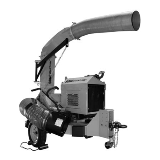
*Actual product may differ from photo
Congratulations on owning a Scag Power Equipment Truck Loader! This manual
contains the operating instructions and safety information for your Scag Power
Equipment Truck Loader. Reading this manual can provide you with assistance
in maintenance and adjustment procedures to keep your Truck Loader
performing to maximum efficiency. The specific models that this book covers
are listed on the inside cover. Before operating your Truck Loader, please read
all the information enclosed.
© 2023
Scag Power Equipment
Division of Metalcraft of Mayville, Inc.
OPERATOR'S
MANUAL
TRUCK LOADER
Industrial Tow Behind
Model:
TLB25-49KBD
PART NO. 03559
PRINTED 9/2023
PRINTED IN USA
Advertisement
Table of Contents

Related Manuals for Scag Power Equipment TLB25-49KBD


Summary of Contents for Scag Power Equipment TLB25-49KBD
- Page 1 TLB25-49KBD *Actual product may differ from photo Congratulations on owning a Scag Power Equipment Truck Loader! This manual contains the operating instructions and safety information for your Scag Power Equipment Truck Loader. Reading this manual can provide you with assistance in maintenance and adjustment procedures to keep your Truck Loader performing to maximum efficiency.
- Page 2 CONCERN, PRUDENCE, AND PROPER TRAINING OF THE PERSONNEL INVOLVED IN THE OPERATION, TRANSPORT, MAINTENANCE, AND STORAGE OF THE EQUIPMENT. This manual covers the operating instructions and illustrated parts list for: TLB25-49KBD with a serial number of X8900001 to X8999999 Always use the entire serial number listed on the serial number tag when referring to this product.
-
Page 3: Table Of Contents
Table of Contents Table of Contents SECTION 1 - GENERAL INFORMATION ...................1 1.1 INTRODUCTION ............................1 1.2 DIRECTION REFERENCE .........................1 1.3 SERVICING THE ENGINE AND DRIVE TRAIN COMPONENTS ............1 1.4 SYMBOLS ..............................2 SECTION 2 - SAFETY INFORMATION ..................3 2.1 INTRODUCTION ............................3 2.2 SIGNAL WORDS ............................3 2.3 BEFORE OPERATION CONSIDERATIONS ....................3 2.4 OPERATION CONSIDERATIONS ......................5... - Page 4 Table of Contents SCAG APPROVED ATTACHMENTS AND ACCESSORIES..............20 INTAKE AND DISCHARGE ASSEMBLY ......................22 IMPELLER HOUSING AND TRAILER ASSEMBLY ..................24 IMPELLER DRIVE ASSEMBLY ........................26 KUBOTA ENGINE ASSEMBLY ........................28 FUEL AND ELECTRICAL SYSTEM ......................30 TLB25 - TRUCK LOADER DECALS ......................32 LIMITED WARRANTY ................INSIDE BACK COVER...
-
Page 5: Section 1 - General Information
Section 1 GENERAL INFORMATION 1.1 INTRODUCTION WARNING Your Scag Power Equipment product was built to the highest standards in the industry. However, the prolonged For pictorial clarity, some illustrations and figures life and maximum efficiency of your Truck Loader in this manual may show shields, guards or plates depends on you following the operating, maintenance open or removed. -
Page 6: Symbols
Section 1 1.4 SYMBOLS SYMBOL DESCRIPTION SYMBOL DESCRIPTION Choke Transmission On/Start Spring Tension on Idler Off/Stop Spinning Fan Blades Thrown Object Hazard Fast Slow Continuously Variable - Linear Pinch Point 481039S Keep Bystanders Away Read Operator's Manual... -
Page 7: Section 2 - Safety Information
Please indicate the complete model and serial number of your Scag Power Equipment Your safety and the safety of others depends significantly product when requesting replacement manuals. - Page 8 Section 2 4. Do not operate when children and/or others are 13. Evaluate the terrain to determine what accessories present. Keep children out of the work area and in and attachments are needed to properly and safely the watchful care of a responsible adult other than perform the job.
-
Page 9: Operation Considerations
Section 2 23. Check operation of brake, tail, side marker and 11. Do not operate around cars, windows, or other items license plate lights frequently. Replace failed or which could be damaged by blown debris. damaged parts as needed. 12. Before attempting to start the engine, inspect the machine, inlet hose, discharge, debris receiver box, 2.4 OPERATION CONSIDERATIONS shields and safety devices for any damage. -
Page 10: Maintenance Considerations And Storage
Section 2 DANGER REAR SUPPORT DO NOT run the engine inside a building or a confined area without proper ventilation. Exhaust fumes are hazardous and contain carbon monoxide which can cause brain injury and death. SPRING LATCH 22. Keep hands and feet away from all other moving parts. -
Page 11: Safety And Instructional Decals
Section 2 2.7 SAFETY AND INSTRUCTIONAL DECALS 485126 484983 485139 485122 Avoid injury from burns - Shut off engine - Allow to cool several minutes - Remove cap slowly - Do not overfill 484292 DIESEL FUEL ONLY 484292... -
Page 12: Section 3 - Specifications
Starter ........................Electric Starting with Solenoid Shift 3.2 IMPELLER Impeller Diameter ..........................Balanced 25" Steel Number of Blades ..........................4 - Blade, 1/2" CFM (cubic feet / min.) - TLB25-49KBD ........................7318 Wear Liner ................................1/4" Steel Intake Hose ................................7' x 16" Discharge ................................6' x 12"... -
Page 13: Section 4 - Operating Instructions
Section 4 OPERATING INSTRUCTIONS 1. Ignition Switch (Figure 4-1). The ignition switch CAUTION is used to start the engine and has three positions; OFF, ON, and START. 2. Engine Throttle Control (Figure 4-1). Use to Do not attempt to operate this machine unless control the engine speed. -
Page 14: Initial Run-In Procedures
Section 4 4.3 CONNECTING TO TOW VEHICLE 5. Safety Chains (Figure 4-1). Use to connect to the tow vehicles cradle draw bar in criss-cross fashion in case of an accidental disconnect. 1. Back the tow vehicle up to the Truck Loader. 6. -
Page 15: Starting The Engine
Section 4 4.4 STARTING THE ENGINE CAUTION CAUTION Tow at speeds appropriate for conditions. Reduce speeds for: • Rough Roads DO NOT USE STARTING FLUIDS. Use of starting fluids in the air intake system may be potentially • Winding Roads explosive or cause a “runaway”... -
Page 16: Hillside Operation
Section 4 4.7 UNCOUPLING THE UNIT FROM THE 9. Plan how to clear the area to reduce clearing time. TOW VEHICLE 10. Collecting debris into piles for the machine to intercept prior to start up will save time and fuel as 1. -
Page 17: After Operation
Section 4 4.8 AFTER OPERATION 7. Pull and turn the spring latch to unlock the pin securing the rear support leg in the transport position. See Figure 4-5. 1. When machine is not in operation, in storage or transporting, lock the hose support boom and secure hose on the storage pin. -
Page 18: Removing Clogged Material
Section 4 3. Keep the entire machine clean to inhibit serious heat damage to the engine. DANGER To avoid injury from burns, allow the engine to cool before removing the fuel tank cap and refueling. 4. Check the tire pressure. Adjust pressure if necessary. -
Page 19: Section 5 - Maintenance
Section 5 MAINTENANCE 5.1 MAINTENANCE CHART - RECOMMENDED SERVICE INTERVALS HOURS PROCEDURE COMMENTS BREAK-IN 100 200 500 (FIRST 10) Check all hardware for tightness Check impeller drive belt tension See Section 5.5 Check engine oil level See engine operator's manual *Clean Truck Loader Check trailer lights for proper Check Daily before operating... -
Page 20: Engine Oil
Section 5 5.2 ENGINE OIL 5. Never fuel the machine indoors or in an enclosed trailer. A. CHECKING ENGINE CRANKCASE OIL 6. Never store the machine or fuel container where there is an open flame, spark or pilot light such as on LEVEL a water heater or other appliances. -
Page 21: Impeller Shaft Bearings And Engine Stub Shaft
2 hours, 4 hours and 8 hours of operation. CHECK BELT Belt alignment and tension are important for proper TENSION HERE performance of your Scag Power Equipment Truck Loader. If you experience frequent belt wear or breakage, see your authorized Scag Power Equipment service center for belt adjustment. -
Page 22: Wheels And Tires
Section 5 5.7 WHEELS AND TIRES Check the condition of wheel assemblies after 8 hours of operation or daily. Maintain tire pressure as indicated on tire sidewall. Replace worn or damaged tires promptly. 5.8 TRAILER LIGHTS Check the trailer lights for proper operation every day before operation. -
Page 23: Section 6 - Illustrated Parts List
Section 6 ILLUSTRATED PARTS LIST 6.1 SCAG APPROVED ATTACHMENTS AND ACCESSORIES. Attachments and accessories manufactured by companies other than Scag Power Equipment are not approved for use on this machine. Scag Power Equipment approved attachments and accessories: Accessories Roadside Package... -
Page 24: Intake And Discharge Assembly
Section 6 INTAKE AND DISCHARGE ASSEMBLY... - Page 25 Nut, Elastic Stop 5/16-18 48135-29 Hose, 16" x 84" - .045 P.U. w/Wire 04001-09 Bolt, 5/16-18 x 1" 04117-01 Nut, Flanged Elastic Stop, 5/16-18 428000 Mounting Bracket, ECU 486683 ECU, TLB25-49KBD 04040-04 Flatwasher, 5/16 - .344 x .688 x .065...
-
Page 26: Impeller Housing And Trailer Assembly
Section 6 IMPELLER HOUSING AND TRAILER ASSEMBLY... - Page 27 Section 6 IMPELLER HOUSING AND TRAILER ASSEMBLY Ref. Part No. Description 485105 Pintle Ring, 3" 485104 Ball Coupler, 2-5/16" (optional) 04001-204 Bolt, Hex Head 5/8-11 x 4-3/4" Grade 8 04043-09 Flatwasher, 5/8-.656 x 1.312 x 0.95 HD 04021-23 Nut, Elastic Stop 1/2-13 04040-13 Flatwasher, 1/2-.562 x 1.375 x .109 04021-07...
-
Page 28: Impeller Drive Assembly
Section 6 IMPELLER DRIVE ASSEMBLY 33 35... - Page 29 Section 6 IMPELLER DRIVE ASSEMBLY Ref. Part No. Description 484992 Bushing, Tapered Lock SK 1-1/2" 04063-34 Key, 3/8 x 3/8 x 2-1/4" 484991 Pulley, Sheave 3V6.5 x 5 SK 04001-131 Bolt, Hex Head 5/8-11 x 1-3/4" 04030-07 Lockwasher, 5/8" Spring 04043-06 Flatwasher, 5/8-.688 x 1.75 x .134 HD 04001-183...
-
Page 30: Kubota Engine Assembly
Section 6 KUBOTA ENGINE ASSEMBLY To Frame To Frame To Frame *Not Shown Engine Oil Drain - p/n 486686 Coolant Over-Flow Bottle - p/n 486682... - Page 31 Section 6 KUBOTA ENGINE ASSEMBLY Ref. Part No. Description 486678 Rain Cap, Air Cleaner 486680 Rain Cap Assy, Exhaust 486674 Air Cleaner Assy. 486676 Air Filter, Safety 486677 Air Filter, Primary 04129-01 Screw, Thumb, 5/16-18 x .625 426691 Enclosure, Cover 04017-16 Screw, Serrated Flange, 5/16-18 x 3/4"...
-
Page 32: Fuel And Electrical System
Section 6 FUEL AND ELECTRICAL SYSTEM To Starter To Ground 12 22 22 12... - Page 33 Section 6 FUEL AND ELECTRICAL SYSTEM Ref. Part No. Description 484989 Battery Box, GRP24 485107 Pad, Battery Hold Down 481176-06 Battery Cable, Red 481176-13 Battery Cable, Black 482283 Battery (not available thru Scag) 04021-08 Nut, Elastic Stop 1/4-20 04040-14 Flatwasher, 1/4-.312 x .750 x .065 04011-11 Screw, #10-32 x .56 HDHW Shakeproof 485053...
-
Page 34: Tlb25 - Truck Loader Decals
Section 6 TLB25 - TRUCK LOADER DECALS 486246 484983 485139 485122 ULTRA LOW WARNING INSTALL BELT COVER BEFORE SULFUR FUEL ONLY OPERATING MACHINE READ OPERATOR'S MANUAL 483402 484739 484739 485126... -
Page 35: Limited Warranty
Loader is used on more than the owners single property, it is deemed commercial use and the “non-commercial” warranty does not apply. Scag Power Equipment reserves the right to deny and / or void the non-commercial warranty if it believes it to be in commercial use.
Need help?
Do you have a question about the TLB25-49KBD and is the answer not in the manual?
Questions and answers