
Summary of Contents for DeLonghi CLIMAVENTACLIMAVENTA HRAN 0011
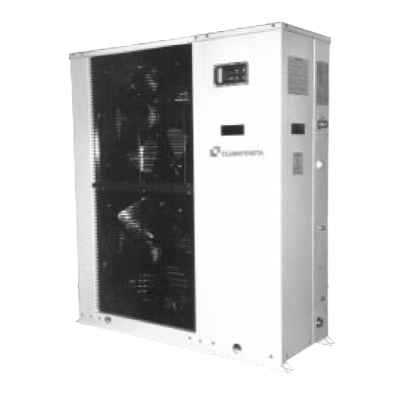
- Page 1 INSTALLATION - OPERATING MANUAL Water chillers and air/water heat pumps with axial-flow fans. HRAT-HRAN 0011÷0121...
-
Page 2: Dimensioned Drawings
DIMENSIONED DRAWINGS 1- Hydraulic connections IN 0011-0031 - 3/4" dia., 0041-0121 - 1"1/4 dia. 2- Hydraulic connections OUT 0011-0031 - 3/4" dia., 0041-0121 - 1"1/4 dia. Dimension 0011 0021 0025 0031 0041 0051 0061 0071 0091 0101 0121 1100 1100 1100 1450 1450... -
Page 3: Choice Of Installation Site
INSTALLATION CHOICE OF INSTALLATION SITE lift truck or similar, bearing in mind the weight distribution of Before installing the unit, agree with the customer the site the unit. To lift the unit, insert tubes long enough to allow where it will be installed, taking the following points into positioning of the lifting slings and safety pins into the special consideration: holes in the bed plate of the unit. -
Page 4: Filling The Installation
Pressure gauge Hydraulic connection diagram with pump installed in installation Vibration damper joint Gate valve UNIT APPLICATION Calibrating valve Flow switch Thermometer Pump Safety valve Air vent 10 Expansion tank 11 Filter 12 Top-up 13 Temperature sensor 14 Differential pressure switch 15 Drain/chemical washing valve If the installation requires a useful head higher than that obtai- The manufacturer is not liable for obstruction, breaka-... -
Page 5: Electrical Connections
ELECTRICAL CONNECTIONS HRAT-HRAN chillers leave the factory completely cabled Voltage must be within a tolerance of ±10% of and ready for connection to the mains electricity supply the rated power supply voltage for the unit (for and for the flow switch, remote ON/OFF switch and pump three phase units, the unbalance between the pha- to be connected to the terminals provided. - Page 6 ELECTRICAL SWITCHBOARD The electrical switchboard is located inside the unit at the top of the technical compartment where the various com- ponents of the refrigerant circuit are also to be found. To access the electrical switchboard, remove the front panel of the unit by undoing the metric screws. To access the components in the electrical switchboard and the terminal boards, undo the two screws on the swit- chboard itself.
- Page 7 To avoid interference due to magnetic ELECTRICAL POWER CONNECTIONS fields, use of screened cable is recommended. For the functional connection of the unit, bring the power The cable should not be more than 100 m supply cable to the electrical switchboard inside the unit long.
- Page 8 ELECTRICAL DIAGRAM HRAT -HRAN SINGLE PHASE HRAT/HRAN English 10/99...
- Page 9 ELECTRICAL DIAGRAM HRAT -HRAN THREE PHASE English 10/99 HRAT/HRAN...
-
Page 10: General Technical Data
GENERAL TECHNICAL DATA HRAT Model 0011 0021 0025 0031 0041 0051 0061 0071 0091 0101 0121 Refrigerating capacity (1) 10,5 12,5 15,0 19,1 22,2 26,8 32,4 Absorbed power compressor (1) 10,5 Total absorbed power (1) 11,3 Total current absorbed at rated conditions (1) A 10,7 13,0 14,1... - Page 11 Model 0061 Model 0071 Model 0091 Ta. Tw Ta. Tw Ta. Tw 15,6 16,1 16,5 17,0 17,4 17,8 19,8 20,3 20,9 21,5 22,1 22,7 23,2 23,9 24,5 25,2 25,9 26,6 25 Pat 25 Pat 25 Pat ∆ ∆ ∆ Pev 27,7 29,4 31,0 32,7 34,4 36,1 Pev 31,2 33,1 35,1 37,1 39,2 41,4 Pev 25,4 27,0 28,6 30,2 31,9 33,6 14,9 15,3 15,8 16,2 16,6 17,0...
- Page 12 Model 0061 Model 0071 Model 0091 Ta. Tw Ta. Tw Ta. Tw 14,9 15,3 15,7 16,1 16,6 16,9 18,8 19,4 19,9 20,5 21,1 21,6 22,1 22,7 23,4 24,0 24,7 25,3 25 Pat 25 Pat 25 Pat ∆ ∆ ∆ Pev 25,2 26,7 28,2 29,7 31,2 32,7 Pev 28,3 30,0 31,8 33,6 35,6 37,5 Pev 23,1 24,5 25,9 27,4 28,9 30,5 14,2 14,6 15,0 15,4 15,8 16,2...
Need help?
Do you have a question about the CLIMAVENTACLIMAVENTA HRAN 0011 and is the answer not in the manual?
Questions and answers