Advertisement
Quick Links
Advertisement

Subscribe to Our Youtube Channel
Related Manuals for Mini-Circuits ZHL-2425-250X+


Summary of Contents for Mini-Circuits ZHL-2425-250X+
- Page 1 ZHL-2425-250X+ Heat Sink Mounting Instructions AN-60-110 www.minicircuits.com...
-
Page 2: Table Of Contents
Table of Contents Introduction ......................1 Importance of the Heat Sink ..................1 Amplifier Mounting Holes ..................2 Heat Sink Mounting Instructions ................4 Fan Recommendations ....................6 Fan Controller Recommendations................8 Final Notes ........................ 9 AN-60-110 ZHL-2425-250+ HEAT SINK MOUNTING INSTRUCTIONS... -
Page 3: Introduction
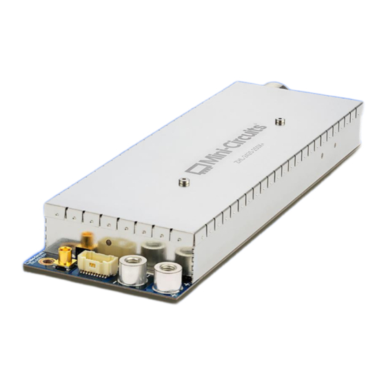
Instead, a heat sink and attached fan can provide a more economical and less bulky cooling solution for single unit evaluation. Mini-Circuits provides the ZHL-2425-250X+ as an amplifier pallet “without a heat sink” leaving the end- user to decide what type of cooling they want to use. -
Page 4: Amplifier Mounting Holes
8 under the cover, sized for M3 socket or pan head screw with head Diameter 5.4 - 5.6 mm AN-60-110 Rev: A DCO-001385 (02/13/24) File: AN-60-110.docx This document and its contents are the property of Mini-Circuits. Page 2 of 9... - Page 5 Figure 2: Outline drawing of the HSK-2425-250+ heat sink, the exact locations of the screw holes are shown Figure 3: ZHL Amplifier module with shield screws shown. AN-60-110 Rev: A DCO-001385 (02/13/24) File: AN-60-110.docx This document and its contents are the property of Mini-Circuits. Page 3 of 9...
-
Page 6: Heat Sink Mounting Instructions
Any electrically non-conductive thermal compound with at least the same thermal conductivity as the one listed should be ok to use. AN-60-110 Rev: A DCO-001385 (02/13/24) File: AN-60-110.docx This document and its contents are the property of Mini-Circuits. Page 4 of 9... - Page 7 Figure 5: Recommendation for the screw to mount amplifier to heat sink Step 4: Replace the shield cover and fasten the shield cover screws. AN-60-110 Rev: A DCO-001385 (02/13/24) File: AN-60-110.docx This document and its contents are the property of Mini-Circuits. Page 5 of 9...
-
Page 8: Fan Recommendations
Fan Recommendations The Mini-Circuits heat sink has been designed with mounting holes for end-mounting 60mm fans. The bottom of the heat sink is covered leaving one inlet and one outlet for air at either end. Our recommendation is to use a single fan on one end of the heat sink oriented so that the direction of airflow is going into the heatsink. - Page 9 (bottom). The recommended fan shown is a 4-wire version. 3-wire and 2-wire versions are also available if PWM control is not needed. AN-60-110 Rev: A DCO-001385 (02/13/24) File: AN-60-110.docx This document and its contents are the property of Mini-Circuits. Page 7 of 9...
-
Page 10: Fan Controller Recommendations
Manufacturer P/N: 08500113 Manufacturer P/N: 0470541000 Figure 9: Connector housing an terminal to interface 4-wire fan with PWM controller AN-60-110 Rev: A DCO-001385 (02/13/24) File: AN-60-110.docx This document and its contents are the property of Mini-Circuits. Page 8 of 9... -
Page 11: Final Notes
PWM controller board, barrel jack added for easily interfacing with a standard 12V power supply, and zip ties for cable management. AN-60-110 Rev: A DCO-001385 (02/13/24) File: AN-60-110.docx This document and its contents are the property of Mini-Circuits. Page 9 of 9... - Page 12 Accordingly, Mini-Circuits assumes no liability therefore. In addition, your use of this document and the information contained herein is subject to Mini-Circuits’ standard terms of use, which are available at Mini-Circuits’ website at www.minicircuits.com/homepage/terms_of_use.html.
Need help?
Do you have a question about the ZHL-2425-250X+ and is the answer not in the manual?
Questions and answers