Advertisement
Quick Links
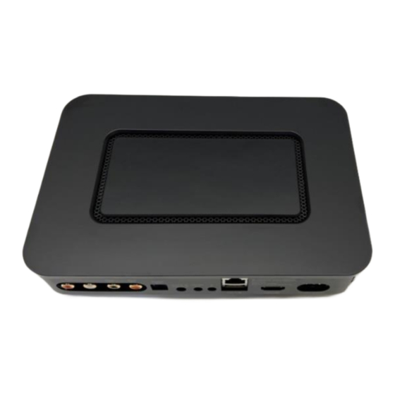
Manual for Sbooster's Active Interface Board (AIB) for the Node N130
Thank you for purchasing the Sbooster-Node N130 AIB to upgrade the
Bluesound Node N130.
In just 20 minutes of your DIY-time you are able to take out the stock SMPS-
board of the Bluesound Node N130 and to connect it to the Sbooster BOTW
P&P ECO 5-6V external power supply.
In the package:
• Active Interface Board (AIB)
• Cryo-treated replacement fuse for BOTW P&P ECO MKII 5-6V, marked
with a black dot.
Notes before you start:
• The AIB for the Node N130 can only work with the BOTW P&P ECO MKII
5-6V, set to 6V
• Make sure the Node N130 and the BOTW P&P ECO MKII 5-6V are
disconnected from the
• Caution: Watch-out for Electrostatic Discharge (ESD).
Make sure that when you are working on the Node N130, the AIB and/or
the BOTW P&P ECO MKII 5-6V, that
prevent damage to the
You can discharge yourself by touching your grounded device like an
Amplifier, Radiator or Fridge, etc.
Needed tools:
• Screwdriver
mains.
you are fully electric discharged to
electronics.
1
Advertisement

Summary of Contents for SBooster Node N130
- Page 1 Notes before you start: • The AIB for the Node N130 can only work with the BOTW P&P ECO MKII 5-6V, set to 6V • Make sure the Node N130 and the BOTW P&P ECO MKII 5-6V are disconnected from the mains.
- Page 2 Step 1: Remove the rear cover, which is attached with a magnet. Step 2: Remove 3 screws to unlock the top of the Node. Step 3: Carefully open the top part of the housing by lifting it from the back of the device, until you hear a loud “click”.
- Page 3 Step 4: Disconnect the white connectors from the sockets. Step 5: Remove 4 screws of the Node’s power supply board and take out the metal bracket that covered the connector. Step 6: Remove 2 screws from the back panel. Then remove the Node’s switching power supply board.
- Page 4 Take out the black plastic sheet. Step 8: Result after removing the internal SMPS and plastic cover sheet. Installing the Sbooster Node AIB Step 9: Insert the AIB so that the pin on the bottom plate fits the hole on the AIB.
- Page 5 Step 10: Place the mains connector plate over the connector and screw the AIB with 4 screws to the enclosure. Step 11: Connect the 4-pin and 2-pin connectors in their matching sockets. Step 12: Screw the 2 screws to tighten the Sbooster connector.
- Page 6 Step 14: Screw the last screws back into place and then install the magnetic panel cover. Now the Bluesound Node is ready to be connected to the Sbooster BOTW P&P ECO 5-6V. Before using, please read the manual of the Sbooster BOTW P&P ECO power supply.
- Page 7 Enjoy more music………...
- Page 8 Changing the fuse of the Sbooster BOTW P&P ECO power supply To change the fuse, the enclosure of BOTW P&P ECO has to be opened. Opening the enclosure is straightforward. Step 1: Turn "OFF" the BOTW P&P ECO and wait for 30 seconds until the green LED is fully dimmed.
- Page 9 4 screws. And you are ready! DO NOT use the BOTW P&P ECO without enclosure cover. The mains filter contains a lethal voltage. Sbooster Manufactured by HD Electronics Ltd. For more information visit: www.sbooster.com For questions contact your dealer, or send us an email:...
Need help?
Do you have a question about the Node N130 and is the answer not in the manual?
Questions and answers