
Related Manuals for Worldwide WDC CONTROL Series

Summary of Contents for Worldwide WDC CONTROL Series
- Page 1 Instruction Manual Variable Speed DC Control WDCCONT WDCCONTREV Phone (800) 808-2131 Fax (800) 711-1616 www.worldwideelectric.com LT84 (0220) A-5-3546F...
-
Page 2: Table Of Contents
WARRANTY WorldWide Electric Corporation (WWE) warrants its products to be free from defects in material and workmanship. The exclusive remedy for this warranty is WWE factory replacement of any part or parts of such product which shall within 12 months after delivery to the purchaser be returned to WWE factory with all transportation charges prepaid and which WWE determines to its satisfaction to be defective. -
Page 3: Introduction
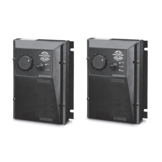
INTRODUCTION • TheWDC Series variable speed DC motor control is a versatile, general purpose control rated to 2 HP. • The control has a dual voltage input (may accommodate either 120 or 240 VAC). It is available with an adjustable HP range of 1/8 thru 1 HP for 120 VAC, and 1/4 thru 2 HP for 240 VAC input. -
Page 4: Wdccont Hook-Up Diagram
WDCCONT HOOK-UP DIAGRAM (SEE PAGE 4 FOR WDCCONTREV) HI (white) WIPER (red) Cur. LO (orange) Accel Comp Lim. DPST SWITCH SPEEDPOT (black) (white (white) or yellow) (black or brown) Inhibit INSIDE OF COVER -1 -2 -3 -4 -5 -6 -7 chassis field* ground... -
Page 5: Wdccontrev Hook-Up Diagram
WDCCONTREV HOOK-UP DIAGRAM Permits reversing of motor. This is accomplished using a 4PDT blocked center switch. When switched between the forward/reverse positions, a delay is encountered due to the blocked center position, which protects the control from any voltage that may be at the armature terminals. -
Page 6: Wiring Procedure & Fusing
WIRING PROCEDURE 1. Size all wires which carry armature or line current to handle currents as specified by national, state, and/or local codes. All other wires may be #18 AWG or smaller as permitted by local code. 2. Separate control wires from all the Armature and AC line wires when routed in conduits or in wire trays. The enclosed version has two threaded holes (1/2"... -
Page 7: Start-Up Procedure & Adjustments
Warning: Do not attempt to perform a Hi-Pot test across AC lines with control in circuit. This will result in immediate or long term damage to the control. START-UP PROCEDURE WARNING: ALL POWER MUST BE TURNED OFF BEFORE PROCEEDING !!! 1. -
Page 8: Trimpot Adjustment Procedure & Setting Chart
TRIMPOT ADJUSTMENT PROCEDURE TRIMPOT FUNCTION ADJUSTMENT SETS MAXIMUM MOTOR SPEED when 1. TURN DRIVE POWER OFF!! speedpot is set at maximum (100% rotation 2. Connect DC Voltmeter: + to +ARM, - to -ARM. CW). CW rotation of MAX trimpot increases 3. -
Page 9: Control Modifications
- check TERMINAL STRIP WIRING for stop correct wiring instructions (note AC line connection in particular) - defective wiring - check wiring - defective component - call WorldWide Distributor or Representative If control still will not operate, consult your WorldWide Electric Distributor or Representative. -
Page 10: Specifications & Typical Motor Currents
SPECIFICATIONS AC input voltage ..........................±10% of rated line voltage Acceleration ........................0.5 to 8.0 seconds (note -17B option) Amps - DC output ..........................150 mA to 10.8 Amps D.C. Controller overload capacity ......................... 150% for one minute Current limit trimpot range ........................... 1.0 to 15.0 Amps D.C. Deceleration (dependent on acceleration time setting) ................
Need help?
Do you have a question about the WDC CONTROL Series and is the answer not in the manual?
Questions and answers