Table of Contents
Advertisement
[BUL
ME~
[SION
REV]
['ICE
N
N
VOR/LOCICOMM AND G/S
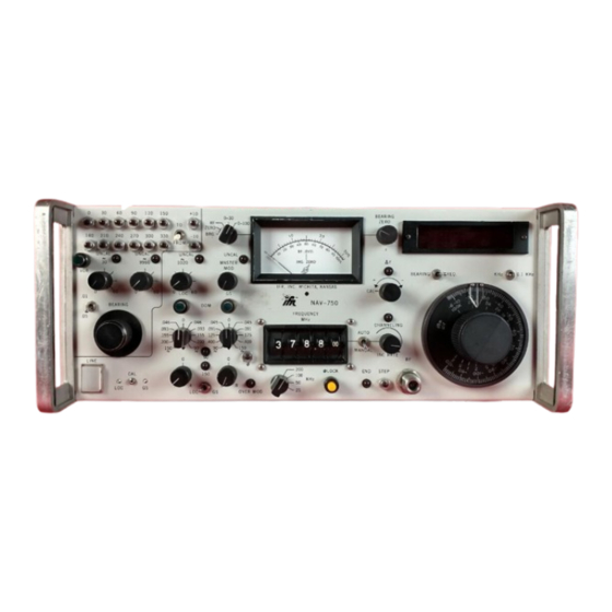
NAV-750, NAV-750A, AND NAV-750B
THIS PUBLICATION SUPERSEDES NAVAIR 17—2OAX—737
DISTRIBUTION STATEMENT C. DISTRIBUTION AUTHORIZED TO U.S. GOVERNMENT AGENCIES
THEIR
AND
CONTRACTORS TO PROTECT PUBLICATIONS REQUIRED FOROFFICIAL USE OR FOR
ADMINISTRATIVEOR OPERATIONAL PURPOSES ONLY. OTHER REQUESTS FOR THIS DOCUMENT
SHALL BE REFERRED TO NAVY MEASUREMENT SCIENCE DIRECTORATE, NAVAL WARFARE
ASSESSMENT DIVISION, P0. BOX
DESTRUCTION NOTICE- FOR UNCLASSIFIED, LIMITED DOCUMENTS, DESTROY BY ANY
METHOD THAT WILL PREVENT DISCLOSURE OF CONTENTS OR "RECONSTRUCTION OF
THE DOCUMENT"
PUBLISHED BY DIRECTION OF COMMANDER NAVAL AIR SYSTEMS COMMAND
This document has been modified primarily
for the purpose of incorporating changes
previously identified in the Metrology Bulletin
as unpublished procedure
(METBUL)
changes.
NAVAIR 17-2OAX-737
TECHNICAL MANUAL
INSTRUMENT CALIBRATION PROCEDURE
BENCH TEST SETS
IFR INC.
DISTRIBUTION WITHIN GIDEP IS AUTHORIZED BY
NAVAL WEAPONS STATION, SEAL BEACH LETTER,
SER 313/0994 DATED 14 MAY 1987
DATED 1 JULY 1991
5000
CORONA. CA 91718-5000
c~Jr,
2 I
1 AUGUST 1995
Advertisement
Table of Contents

Related Manuals for IFR NAVAIR NAV-750

Summary of Contents for IFR NAVAIR NAV-750
- Page 1 NAVAIR 17-2OAX-737 TECHNICAL MANUAL INSTRUMENT CALIBRATION PROCEDURE VOR/LOCICOMM AND G/S BENCH TEST SETS IFR INC. NAV-750, NAV-750A, AND NAV-750B DISTRIBUTION WITHIN GIDEP IS AUTHORIZED BY NAVAL WEAPONS STATION, SEAL BEACH LETTER, SER 313/0994 DATED 14 MAY 1987 THIS PUBLICATION SUPERSEDES NAVAIR 17—2OAX—737 DATED 1 JULY 1991 DISTRIBUTION STATEMENT C.
-
Page 2: Table Of Contents
NAVAIR 17—2OAX—737 TABLE OF CONTENTS Section Page Introduction and Description Equipment Requirements Preliminary Operations Calibration Process Frequency Accuracy Tests Attenuator Frequency Response Tests Attenuator Linearitv Tests DEMOD Tones and DC OFFSET Tests Tone Frequency Tests Tone Distortion Tests Percent Amplitude Modulation of Tones and Modulation Meter Tests RF Level Meter Tests VOR Bearing Tests 4.10... -
Page 3: Introduction And Description
NAVAIR 17—2OAX—737 SECTION 1 INTRODUCTION AND DESCRIPTION 1.1 This procedure describes the calibration of IFR Inc. NAV—750, NAV—750A, NAV—750B VOR/LOC/COMM and G/S Bench Test Sets. The instrument being calibrated is referred to herein as the TI (Test Instrument). 1.2 This procedure was derived from draft prepared by NADEP Cherry Point. All comments concerning this procedure should be directed to Navy Measurement Science Directorate, Naval Warfare Assessment Division, P.O. - Page 4 NAVAIR 1 1—2OAX—737 Performance Test Characteristics Specifications Method Measured with a signal Tone modulation VOR 30 Hz: 20% AM analyzer. Tolerance: ±1.2% VOR 9960 Hz: 30% AM Tolerance: ±1.2% LOC 90 Hz: 20% AM Tolerance: ±0.8% LOC 150 Hz: 20% AM Tolerance: ±0.8% G/S 90 Hz: 40% AM Tolerance: ±1.6%...
- Page 5 NAVAIR 17—2OAX—737 Performance Test Characteristics Specifications Method NAV-750A and NAV-750B Frequency: 108.000 MHz Tolerance: 75 dB below carrier ±12.5 kHz, and ~83dB below carrier ±25.0 kHz in 300 Hz resolution bandwidth NAV-750A only Frequency: 334.700 MHz Tolerance: 66 dB below carrier ±12.5 kHz, dB below carrier ±25.0 kHz in 300 Hz...
-
Page 6: Equipment Requirements
NAVAIR 17—2OAX—737 Performance Test Characteristics Specifications Method NAV-750 and NAV-750B Frequency: 334.000 MHz Tolerance: >80 dB below carrier ±100 kHz in 1 kHz resolution bandwidth NAV—750A only Frequency: 108.000 MHz Tolerance: >82dB below carrier ±100 kHz in 1 kHz resolution bandwidth Frequency: 334.000 MHz Tolerance: >82 dB below carrier... - Page 7 NAVAIR 17—2OAX—737 Calibration Item Minimum Use Equipment Specifications 2.1 Oscilloscope Bandwidth: 50 MHz Tektronix Uncertainty: ±3%time base 7704AM0D 1 29GOPTO3, Dual trace and delayed 7904AOPT03 or sweep capability 7704AM0D129G with 7A26 and 7B92A plug—ins 2.2 Electronic Frequency range: 25 Hz to 335 MHz Hewlett—Packard counter 5335A0PT010, 030, 040,...
-
Page 8: Preliminary Operations
NAVAIR 17—2OAX--737 SECTION 3 PRELIMINARY OPERATIONS 3.1 Ensure that all power switches are set to off, and set all auxiliary equipment controls as necessary to avoid damage to the equipment and so that dangerous voltages will not be present on output terminals when the power switches are turned on. -
Page 9: Calibration Process
NAVAIR 17—2OAX—737 SECTION 4 CALIBRATION PROCESS NOTE Unless otherwise specified, verify the results of each test and take corrective action whenever the test requirement is not met,before proceeding. 4.1 FREQUENCY ACCURACY TESTS 4.1.1 Set the TI controls as follows: FREQUENCY MHz switches to 108.000 MASTER MOD control to UNCAL [fullyccw (0)]... -
Page 10: Attenuator Frequency Response Tests
NAVAIR 17—2OAX—737 4.2 ATI’ENUATOR FREQUENCY RESPONSE TESTS 4.2.1 Connect the power sensor to the power meter. Zero and reference calibrate the power sensor and power meter. 4.2.2 Set the TI attenuator to —30 dBm. and the TI frequency switches to 108 MHz. Connect the power sensor input to the TI RF output connector. -
Page 11: Attenuator Linearitv Tests
NAVAIR 17—2OAX—737 4.2.12 Set the TI FREQUENCY MHz switches to the following settings. At each setting, verify that the power meter indicates within the tolerance limits listed. Power Meter Tolerance Limits FREQUENCY MHz Switch Setting (dBm) —28.5 to —31.5 072.000 074.000 “... -
Page 12: Demod Tones And Dc Offset Tests
NAVAIR 17—2OAX—737 4.4 DEMOD TONES AND DC OFFSET TESTS 4.4.1 Set the TI controls as follows: BEARING-FREQ switch to FREQ MASTER MOD control to CAL (UNCAL lamp off) 1020 Hz indent tone MOD control to CAL (UNCAL lamp off) 9960 Hz FM tone MOD control to CAL (UNCAL lamp off) 30 Hz tone MOD control to CAL (UNCAL lamp off) -
Page 13: Tone Frequency Tests
NAVAIR 17—2OAX—737 4.4.3.15 Verify that the DMM indicates between —40.0 and 40.0 mV dc. 4.4.3.16 Adjust the TI 9960 FM tone modulation control toUNCAL [fully ccw (0)]. 4.4.3.17 Verify that the oscilloscope displays a 30 Hz tone, and that the DMM indicates between —40.0 and +40.0 mV dc. -
Page 14: Fm Deviation Display
NAVAIR 17—2OAX—737 4.5.3 Verify that the electronic counter indicates between 29.994 and 30.006 Hz. 4.5.4 Set the TI FREQUENCY MHz switches to 108.100, and the G/S DDM switch to 90 Hz. 4.5.5 Disconnect the electronic counter from the TI 30 Hz REF jack, and connect it to the TI rear panel DEMOD jack. -
Page 15: 9960 Hz Deviation (Expanded)
NAVAIR 17—2OAX—737 4.5.18 Use the oscilloscope delayed sweep function to expand the portion of the TI signal indicated in Figure 1, with the oscilloscope delayed time base set for 10 p.s/div. such that the display is similar to Figure 2. Verify that the deviation of the expanded display corresponds to delta time 48.5 p.s ±2.4 p.s. -
Page 16: Tone Distortion Tests
NAVAIR 17—2OAX—737 4.5.30 Set the meter function and tone switches 3000 Hz. • 4.5.31 Verify that the electronic counter indicates between 2979.0 and 3021.0 Hz. 4.5.32 Disconnect the electronic counter and the oscilloscope from the TI. 4.6 TONE DISTORTION TESTS 4.6.1 Set the TI controls to the following positions: FREQUENCY MHz switches to 108.000... -
Page 17: Percent Amplitude Modulation Of Tones And Modulation Meter Tests
NAVAIR 17—2OAX—737 4.6.15 Set the TI FREQUENCY MHz switches to 108.000. 4.6.16 Adjust the TI 9960 FM tone modulation control to the UNCAL [fully ccw (0)] position. Set the distortion analyzer controls for distortion measurement of a 30 Hz fundamental, as applicable. 4.6.17 Verify that the distortion analyzer indicates ~0.5% total harmonic distortion. - Page 18 NAVAIR 17—2OAX—737 4.7.2 Connect the signal generator calibrator sensor module input to the TI RF output connector. 4.7.3 Press the signal generator calibrator INSTR PRESET key (Blue key, AUTOMATIC OPERATION key), and ensure that the signal generator calibrator is in the FREQ measurement mode and tunes to the TI FREQUENCY MHz switches setting.
- Page 19 NAVAIR 17-2OAX-737 4.7.25 Set the TI LOC DDM switch to 150 Hz. 4.7.26 Verify that the signal generator calibrator indicates between 38.4% and 41.6% AM modulation, and record the reading. 4.7.27 Verify that the TI meter indicates within ±1.6% of the recorded value in step 4.7.26. 4.7.28 Set the TI LOC DDM switch to 0, and the FREQUENCY MHz switches to 118.000.
-
Page 20: Rf Level Meter Tests
NAVAIR 17—2OAX—737 4.8 RF LEVEL METER TESTS 4.8.1 Set the TI controls as follows: FREQUENCY MHz switches to 108.000 Meter function switch to ±1.5 4.8.2 Verify that the TI meter needle is aligned over the RF level vertical mark within n eedle widths. - Page 21 NAVAIR 17—2OAX—737 4.9.5 Set the TI TO—FROM switch to the FROM position. ±0.05°. 4.9.6 Verify that the navigation indicator T/S indicates 180.00° 4.9.7 Set the TI TO—FROM switch to the TO position, and press the 180°VOR bearing select pushbutton. Ensure that the TI bearing display indicates 180°. 4.9.8 Verify that the navigation indicator T/S indicates 180.00°±0.05°.
-
Page 22: Loc Centering Test 19 Gis Centering Test
NAVAIR 17—2OAX—737 4.10.6 Verify that the difference between the 150 Hz DEMOD voltage recorded in step 4.10.3, and the 90Hz DEMOD voltage recorded in step 4.10.5, is ~2.75 mV rms. 4.11 GIS CENTERING TEST 4.11.1 Set the TI controls as follows: LOC—G/S switch to LOC DDM switch to 150 Hz... - Page 23 NAVAIR 17—2OAX—737 4.12.4 Set the TI FREQUENCY MHz switches to each of the following settings. At each setting, verify that the harmonics (using the spectrum analyzer tuned to the TI frequencies and its harmonics) of all the selected TI frequencies are 30 dB below the carrier level. FREQUENCY MHz Switches Setting 108.000...
-
Page 24: Spectral Purity Tests (Nav-750A Only)
NAVAIR 17—2OAX—737 4.12.15 Set the TI frequency switches to 334.700 MHz. 4.12.16 Verify that the harmonic spurious noise is 63 dB below the carrier level at ±12.5 kHz from the TI 334.700 MHz carrier frequency. 4.12.17 Verify that the harmonic spurious noise is ~74 dB below the carrier level at ±25.0 kHz from the TI 334.700 MHz carrier frequency. - Page 25 NAVAIR 17—2OAX—737 4.13.4 Set the TI FREQUENCY MHz switches to each of the following settings. At each setting, verify that the harmonics (using the spectrum analyzer tuned to the TI frequencies and its harmonics) of all the selected TI frequencies are ~30 dB below the carrier level. FREQUENCY MHz Switches Setting 108.000...
-
Page 26: Spectral Purity Tests (Nav-750B Only)
NAVAIR 17—2OAX—737 4.13.16 Verify that the harmonic spurious noise is 75 dB below the carrier level at ±12.5 kHz from the TI 108.000 MHz carrier frequency. 4.13.17 Verify that the harmonic spurious noise is 83 dB below the carrier level at ±25.0 kHz from the TI 108.000 MHz carrier frequency. - Page 27 NAVAIR 17—2OAX—737 NOTE For the following tests, set the spectrum analyzer frequency span and center frequency controls as necessary to check the level of the harmonics of the TI signals. 4.14.4 Set the TI FREQUENCY MHz switches to the following settings. At each setting, verify that the harmonics (using the spectrum analyzer tuned to the TI frequencies and its harmonics) of all the selected TI frequencies are ~30 dB below the carrier level.
- Page 28 NAVAIR 17—2OAX—737 4.14.12 Set the TI FREQUENCY MHz switches to 108.000. 4.14,13 Set the spectrum analyzer for a frequency span of 5 kHz/div, the resolution bandwidth to 300 Hz, the video bandwidth to 10 Hz, and the reference level and position controls as necessary for a single—sideband noise measurement at ±20 kHz from the TI 108.000 MHz carrier frequency.
-
Page 29: Residual Fm Tests
NAVAIR 17—2OAX—737 4.15 RESIDUAL FM TESTS 4.15.1 Set the TI controls as follows: FREQUENCY MHz switches to 118.000 Output attenuator control to -120 dBm MASTER MOD control to UNCAL [fullyccw (0)] 1020 Hz indent tone MOD control to UNCAL [fully ccw (0)] UNCAL [fully ccw (0)] 9960 Hz FM tone MOD control to 30 Hz tone MOD control to... - Page 30 NAVAIR 17—2OAX—737 CALIBRATION CHECKLIST IFR Inc. NAV—750, NAV—750A, and NAV—750B VOR/LOC/COMM and G/S Bench Test Sets TEST INST (S) NA 17-2OAX-737 PROC. NO. MFG. MODEL SER. NO. PROCEDURE MEASURED VALUES FUN~flONTESTED NOMINAL FIRST RUN SECOND RUN CALIBRATION TOLERANCES STEP Meter Zero Adjust, if necessary ——...
-
Page 31: Navy Calibration Checklist
NAVAIR 17—2OAX—737 CALIBRATION CHECKLIST IFR Inc. NAV—750, NAV-750A, and NAV—750B VOR/LOC/COMM and G/S Bench Test Sets TEST INST (S) NA 17-2OAX-737 PROC. NO. MFG. MODEL SER. NO. PROCEDURE MEASURED VALUES FUNCTION TESTED NOMINAL CALIBRATION TOLERANCES FIRST RUN SECOND RUN STEP... - Page 32 NAVAIR 17—2OAX—737 CALIBRATION CHECKLIST IFR Inc. NAV-750, NAV-750A, and NAV-750B VOR/LOC/COMM and G/S Bench Test Sets TEST INST (S) NA 17-2OAX-737 PROC. NO. MFG. MODEL SER. NO. MEASUPFD VALUES °~ PROCEDURE CALIBRATION TOLERANCES FUNCTION TESTED NOMINAL FIRST RUN SECOND RUN...
- Page 33 NAVAIR 17—2OAX—737 CALIBRATION CHECKLIST IFR Inc. NAV-750, NAV-750A, and NAV-750B VOR/LOC/COMM and G/S Bench Test Sets TEST INST (S) NA 17-2OAX-737 PROC. NO. MFG. MODEL SER. NO. PROCEDURE MEASURED VALUES CALIBRATION TOLERANCES FUNCTION TESTED NOMINAL FIRST RUN SECOND RUN STEP...
- Page 34 NAVAIR 17—2OAX—737 CALIBRATION CHECKLIST IFR Inc. NAV—750, NAV—750A, and NAV—750B VOR/LOC/COMM and G/S Bench Test Sets TEST INST NA 17-2OAX-737 PROC. NO. MFG. MODEL SER. NO. PROCEDURE MEASURED VALUES FUNCTION TESTED NOMINAL FIRST RUN SECOND RUN CALIBRATION TOLERANCES STEP 28.8% to 31.2%...
- Page 35 NAVAIR 17—2OAX—737 CALIBRATION CHECKLIST IFR Inc. NAV- 750, NAV-750A, and NAV—750B VOR/LOC/COMM and 0/S Bench Test Sets TEST INST NA 17-2OAX-737 PROC. NO. MFG. MODEL SER. NO. PROCEDURE MEASURED VALUES CALIBRATION TOLERANCES FUNCTION TESTED NOMINAL FIRST RUN SECOND RUN STEP VOR Bearing Tests —...
- Page 36 NAVAIR 17—2OAX—737 CALIBRATION CHECKLIST IFR Inc. NAV-750, NAV-750A, and NAV—750B VOR/LOC/COMM and G/S Bench Test Sets TEST INST (S) NA 17-2OAX-737 PROC. NO. MFG. MODEL SER. NO. PROCEDURE MEASURED VALUES CALIBRATION TOLERANCES FUNCTION TESTED NOMINAL FIRST RUN SECOND RUN STEP SSB noise 68 dBc 4.12.9...
- Page 37 NAVAIR 17—2OAX—737 CALIBRATION CHECKLIST IFR Inc. NAV-750, NAV-750A, and NAV-750B VOR/LOC/COMM and G/S Bench Test Sets TEST INST (S) NA 17-2OAX-737 PROC. NO. MFG. MODEL SER. NO. PROCEDURE MEASUPED VALUES FUNCTION TESTED NOMINAL FIRST RUN SECOND RUN CALIBRATION TOLERANCES STEP 4.14...
Need help?
Do you have a question about the NAVAIR NAV-750 and is the answer not in the manual?
Questions and answers