
Related Manuals for Anschutz 133-811.NG001

Summary of Contents for Anschutz 133-811.NG001
- Page 1 Anschütz GmbH Zeyestr. 16-24 24106 Kiel Germany www.anschuetz.com Digital Repeater Compass Operator and Service Manual Type: 133-811.NG001 Edition: 001 10000001258...
- Page 2 Copyright Dieses Dokument sowie dessen Inhalt sind urheberrechtlich This document and its content are copyright protected. Distribution, geschützt. Die Weitergabe,Vervielfältigung und Speicherung sowie reproduction and storage as well as translation and exploitation of die Übersetzung wie auch Verwendung dieses Dokuments oder this document and its content, in whole or in parts and regardless of dessen Inhalts, als Ganzes oder in Teilen und egal in welcher Form what form, are prohibited without prior express written permission.
-
Page 3: Table Of Contents
Table of Contents Table of Contents List of Figures..............................III List of Tables................................ V List of Abbreviations............................VII Introduction................................ 1 Preliminary Remarks............................. 1 Change History.............................. 1 Safety................................1 General Safety Regulations........................2 General Safety Instructions........................3 Electrostatic Discharge..........................3 List of Further Documents..........................4 List of Annex Documents.......................... - Page 4 Table of Contents 2.5 Normal Operation Procedures........................18 2.5.1 Adjust the Brightness........................18 2.5.2 Freeze Heading Indication......................18 2.5.3 Test Illumination..........................18 2.6 Emergency Operation Procedures......................19 2.7 Setting out of Operation......................... 19 2.7.1 Procedures for Longer Time Setting out of Operation..............19 3 Troubleshooting.............................20 3.1 Troubleshooting Table..........................20 4 Maintenance and Repair..........................22 5 Installation and Maintenance........................23 5.1 Safety Instructions for Installation and Maintenance................
-
Page 5: List Of Figures
List of Figures List of Figures Fig. 1: Electrostatic Discharge, Protected Area..................... 3 Fig. 2: Digital Repeater Compass, Equipment Overview..................6 Fig. 3: Operating Elements and Indicators......................7 Fig. 4: NMEA Connection Diagram........................24 Fig. 5: 00-0000..............................28 Edition: 001 10000001258... - Page 6 List of Figures 10000001258 Edition: 001...
-
Page 7: List Of Tables
List of Tables List of Tables Tab. 1: Change History............................1 Tab. 2: List of Further Documents......................... 4 Tab. 3: Dimensional Drawings..........................4 Tab. 4: Available NMEA Telegram Formats......................16 Edition: 001 10000001258... - Page 8 List of Tables 10000001258 Edition: 001...
-
Page 9: List Of Abbreviations
List of Abbreviations List of Abbreviations ESD Protected Area Electrostatic Discharge ISPC Illustrated Spare Parts Catalog NMEA National Marine Electronics Association Edition: 001 10000001258... - Page 10 List of Abbreviations 10000001258 VIII Edition: 001...
-
Page 11: Introduction
Introduction Introduction Preliminary Remarks The present manual is a description and reference book only. It is intended to answer questions and to solve problems in the quickest possible manner. Read and follow the instructions and notes in this manual before operating the equipment. For this purpose, refer to the table of contents and read the corresponding chapters thoroughly. -
Page 12: Safety
Introduction Safety General Safety Regulations The following safety symbols are used in this manual: WARNING! Warning statements indicate a hazardous situation that, if not avoided, could result in minor, moderate or serious injury, or death Consequence • Preventive action CAUTION! Caution statements indicate a hazardous situation that, if not avoided, could result in material damage... -
Page 13: General Safety Instructions
Introduction General Safety Instructions Electrostatic Discharge Fig. 1: Electrostatic Discharge, Protected Area Table Mat Ground Cord Dissipative Shoes Floor Mat Wrist Band Wrist Strap Common Ground Ground Point Any product which is labeled as shown is electrostatic sensitive. If proper precautions are not taken, handling or working on Electrostatic Discharge (ESD) -
Page 14: List Of Further Documents
Introduction List of Further Documents Tab. 2: List of Further Documents Documentation No. Designation 4423 Magnetic Sonde 108-010.NG001-NG004 E01 OP SE List of Annex Documents Tab. 3: Dimensional Drawings Drawing No. Designation 133-811.HP005 Digital Repeater Compass 133-811.HP015 Digital Repeater Compass 133-811.NG011 E02 10000001258 Edition: 001... -
Page 15: Description
1 Description 1 Description 1.1 Purpose The Digital Repeater Compass is designed to indicate the ship’s heading referred to north, which has been ascertained by the gyro/magnetic compass (GPS/SAT compass for development status E02 only). 1.2 Development Status The Digital Repeater Compass exists in 2 development statuses, E01 and E02. Depending on the development status, the configuration and operation of the unit might differ. -
Page 16: Technical Description
1 Description 1.4 Technical Description The heading is read at a 7-segment LCD display (luminous numerals). The numerals are recognizable from up to 10 m, even when viewed at different angles. The gyro heading is shown in degrees and decimal degrees. The decimal digit is displayed smaller to prevent erroneous reading. -
Page 17: Operating Elements And Indicators
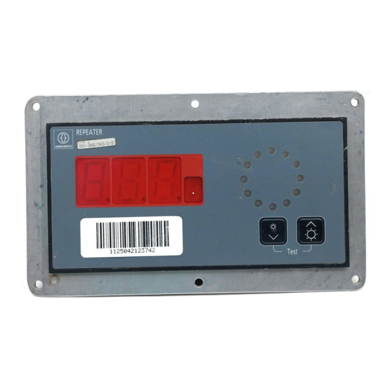
1 Description 1.5 Operating Elements and Indicators Fig. 3: Operating Elements and Indicators Position Area/Element Description Display Shows the current heading LED Ring Shows rate of turn and direction of turn Brightness Down: Reduces the brightness of the illu- mination Pushbuttons Brightness Up: Increases the brightness of the illumi- nation 1.5.1 ... - Page 18 1 Description Indication Description The LEDs in the LED ring light up green (turn to starboard) or red (turn to port). Valid Heading from Magnetic Compass The current heading is indicated without a grad- uation of a tenth of a degree. A degree sign is shown instead.
-
Page 19: Outfit And Accessories
1 Description Indication Description Valid Heading from GPS/SAT Compass The current heading is indicated with a gradua- tion of a tenth of a degree. The current heading alternates with the indica- tion GPS. The LEDs in the LED ring light up green (turn to starboard) or red (turn to port). -
Page 20: Operation
2 Operation 2 Operation 2.1 Preliminary Remarks User Rights The manual is a complete documentation of the system or equipment. Some functions may not be accessible depending on user rights. All functions or operations are described irrespective of the actual user rights of the user. Markup Elements The manual uses different markup elements for hardware and software. -
Page 21: System Configuration
2 Operation 2.3 System Configuration 2.3.1 Development Status E01 2.3.1.1 Select Heading Source Procedure 1. Press and hold the pushbuttons Brightness Up and Brightness Down simultaneously for approximately 10 seconds. ► After approximately 5 seconds the illuminations light up at maximum brightness. Keep the pushbuttons pressed. -
Page 22: Display Current Interface
2 Operation 2.3.1.3 Display Current Interface Procedure 1. Press and hold the pushbuttons Brightness Up and Brightness Down simultaneously for approximately 10 seconds. ► After approximately 5 seconds the illuminations light up at maximum brightness. Keep the pushbuttons pressed. ► After approximately 10 seconds the display shows the current software version, for example P1.0.0. -
Page 23: Select Heading Source
2 Operation ► Indication Description Software Status Shows the current version of the Software. E.g. P008 E00.00 Heading Source Possible indications: GM: Gyro or Magnetic compass G: Gyro compass M: Magnetic compass Heading Offset Possible indications: 000°: Heading without offset 180°: Heading with offset of 180° Data Format Possible indications: HSEr: Heading serial (Anschütz Coursebus) -
Page 24: Select Heading Source Gyro Or Magnetic
2 Operation 2.3.2.2.1 Select Heading Source Gyro or Magnetic Procedure 1. Press and hold the pushbuttons Brightness Up and Brightness Down simultaneously until the display shows -CF-. ► The repeater is in configuration mode. ► The LED ring lights up in orange. 2. -
Page 25: Activate / Deactivate Heading Offset
2 Operation ► The display shows M. If M is flashing, this parameter is active. 5. To activate this parameter, press the pushbutton Brightness Down. ► The parameter starts flashing and is active. ► Configuration mode closes after approximately 15 seconds without pressing a button. -
Page 26: Activate / Deactivate Led Rate Of Turn Indicator
2 Operation 2.3.2.5 Activate / Deactivate LED Rate of Turn Indicator Procedure 1. Press and hold the pushbuttons Brightness Up and Brightness Down simultaneously until the display shows -CF-. ► The repeater is in configuration mode. ► The LED ring lights up in orange. 2. -
Page 27: Activate / Deactivate Nmea Telegram Formats
2 Operation Display Indication Telegram Format HCHDG: Magnetic compass, heading with variation and de- viation xxHDG: Heading source not defined, heading with variation and deviation HCHDM: Magnetic compass, heading xxHDM: Heading source not defined, heading 2.3.2.6.1 Activate / Deactivate NMEA Telegram Formats Procedure 1. -
Page 28: Setting Into Operation
2 Operation 2.4.2 Setting into Operation Procedure 1. Switch on the power supply of the Digital Repeater Compass. ► The unit starts up automatically and is ready for operation. 2.5 Normal Operation Procedures 2.5.1 Adjust the Brightness Procedure Note To use an external dimmer, the brightness of the Digital Repeater Compass must be set to minimum. -
Page 29: Emergency Operation Procedures
2 Operation – Pushbuttons – LED ring ► The illumination stays on as long as the pushbuttons are pressed, but for a maximum of approximately 5 seconds. After that, configuration mode starts and the illumination returns to normal. 2. Release the pushbuttons. 2.6 ... -
Page 30: Troubleshooting
3 Troubleshooting 3 Troubleshooting 3.1 Troubleshooting Table Note Bla Bla Test Development Status E01 No. Failure Possible Cause Remedy The display shows flashing Cable to the interface in- Check the polarity of the terchanged connection at terminals 6 and 7 Data to the interface un- known or corrupted Check the data of the telegrams... - Page 31 3 Troubleshooting No. Failure Possible Cause Remedy Replace the cable to termi- nals 6 and 7 The display shows flashing No data telegram to the in- Check cable contacts on terface the heading source system The LED ring flashes or- No cable connection at the Check the connection of ange interface...
-
Page 32: Maintenance And Repair
4 Maintenance and Repair 4 Maintenance and Repair The Digital Repeater Compass requires no regular maintenance. The Digital Repeater Compass cannot be repaired. In case of faults, the whole unit must be replaced. 10000001258 Edition: 001... -
Page 33: Installation And Maintenance
5 Installation and Maintenance 5 Installation and Maintenance 5.1 Safety Instructions for Installation and Maintenance WARNING! Danger due to maintenance and service by unskilled personnel Risk of serious injury and material damage • Keep all unskilled personnel away from the working area. •... -
Page 34: Initial Operation Procedures
5 Installation and Maintenance Fig. 4: NMEA Connection Diagram Note To control the brightness of the Digital Repeater Compass with an external dimmer set the brightness of the repeater to minimum. 5.2.2 Initial Operation Procedures Procedure 1. Switch on power supply of the unit. ►... -
Page 35: Transport And Storage
6 Transport and Storage 6 Transport and Storage 6.1 Preservation, Packing and Storage Preservation All components / devices require no special preservation procedures. Packing All components / devices are packed with a special protection against humidity. The package contains desiccants and a humidity indicator. The humidity indicator can be read from the outside through a window and must be checked regularly. -
Page 36: Transport
6 Transport and Storage Color Indication Inside Humidity Necessary Action 40 % patch: pink > 40 % Desiccants must be replaced Components / devices must be checked for hu- midity, 50 % patch: pink > 50 % Desiccants must be replaced, Packaging must be checked for damages Note Opening and closing the packing to exchange the desiccants must be done by... -
Page 37: Spare Parts Catalog
7 Spare Parts Catalog 7 Spare Parts Catalog 7.1 General Remarks All depicted items in the following figure(s) which are not mentioned in the corresponding table(s) are not available as spare part for this unit. Since further development may cause modifications to existing equipment, its conformity with the relevant illustrations and drawings is not always ensured. -
Page 38: Digital Repeater Compass
7 Spare Parts Catalog 7.3 Digital Repeater Compass Fig. 5: 00-0000 Fig. No. Designation 1. Part No. Remarks Item No. 2. Part No. 00-0000 Digital Repeater Compass 133-811.NG010 4002764 Color: gray RAL 7012 00-0000 Digital Repeater Compass 133-811.NG010 4002765 Color: black RAL 9005 00-0000 Digital Repeater Compass 133-811.NG011... -
Page 39: Annex
8 Annex 8 Annex Edition: 001 10000001258... - Page 40 8 Annex 10000001258 Edition: 001...
Need help?
Do you have a question about the 133-811.NG001 and is the answer not in the manual?
Questions and answers
How to adjust the slave repeater or to snych.
To adjust the slave repeater on Anschutz part number 133-811.NG001, follow these steps:
1. Mounting: Mount the repeater using the drilling scheme provided in the dimensional drawings.
2. Connection: Connect the repeater to a serial NMEA or Anschütz Course Bus interface.
3. Power On: Switch on the power supply. The Digital Repeater Compass will start.
4. Brightness Adjustment:
- To control brightness with an external dimmer, first set the repeater’s brightness to minimum.
5. Configuration Mode:
- To adjust settings like source or rate of turn indicator:
- Press and hold both Brightness Up and Brightness Down buttons until the display shows "-CF-". The repeater enters configuration mode.
- Use Brightness Up to scroll through options (e.g., Son/Soy for source, roy/ron for rate of turn).
- Use Brightness Down to toggle between options.
- Wait ~15 seconds for the mode to exit and save changes.
These steps allow configuration and adjustment of the slave repeater.
This answer is automatically generated