Table of Contents
Advertisement
Quick Links
ELcon
Construction, operating and functional description
Consulting & Engineering
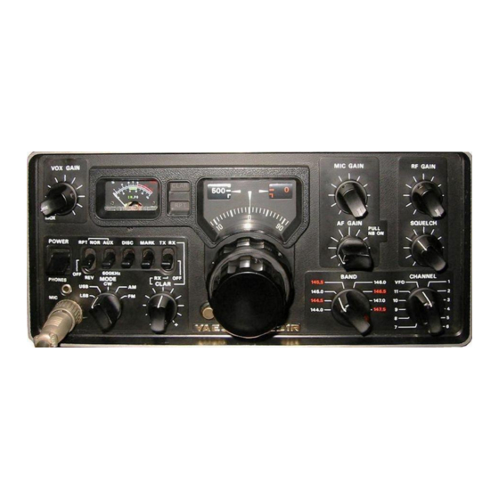
EL-32
Digital replacement display kit
incl. CTCSS function for the
YAESU FT-221R
from SW-Version 2.0e
January 18, 2024
Brunnhaldenstrasse 8
3510 Konolfingen
Switzerland
Phone
+41 (0) 31 792 04 61
E-Mail
info@elcon.ch
Shop
http://shop.elcon.ch
Advertisement
Table of Contents

Summary of Contents for Elcon EL-32
- Page 1 Phone +41 (0) 31 792 04 61 Consulting & Engineering 3510 Konolfingen E-Mail info@elcon.ch Switzerland Shop http://shop.elcon.ch EL-32 Digital replacement display kit incl. CTCSS function for the YAESU FT-221R Construction, operating and functional description from SW-Version 2.0e January 18, 2024...
-
Page 2: Table Of Contents
Disclaimer of liability ......................33 PCB assembly ........................34 Schematic ..........................35 Notes ............................ 36 Important! Advices or tips for the correct function of the EL-32. Caution! The instructions must be observed carefully. January 18, 2024, © Elcon, Switzerland Page2 / 36... -
Page 3: Introduction
Soldering is one of the most important aspects of setting up this device. A bad solder joint - even with a carefully assembled kit - can make it impossible to operate the unit and lead to frustration. January 18, 2024, © Elcon, Switzerland EL-32_V3.0a_en.docx Page3 / 36... - Page 4 ±0.25% = 10'000’000 violet ±0.1% = 100'000’000 gray = 1'000'000’000 white Table 1 Note: all polarized components (diodes, transistors, capacitors, ICs, relays, etc.) must have the correct mounting orientation. January 18, 2024, © Elcon, Switzerland Page4 / 36 EL-32_V3.0a_en.docx...
-
Page 5: Parts Lists
Spacer bolt M3x12mm Component 19 Screws M3x6mm Component 20 Foil for display red Component 21 Polarization film for display Component 27 PCB EL-32 Board version 2.1b [Component 15] Table 2 January 18, 2024, © Elcon, Switzerland EL-32_V3.0a_en.docx Page5 / 36... - Page 6 Component 17 Component 18 Component 19 Component 20 Component 21 Component 22 Component 23 Component 24 Component 25 Component 26 Component 27 Component 28 Component 29 Component 30 Table 3 January 18, 2024, © Elcon, Switzerland Page6 / 36 EL-32_V3.0a_en.docx...
-
Page 7: Step By Step Assembly And Testing Of Printed Circuit Boards
Strip approx. 15 mm off the second end of the coaxial cable. Unbraid the shielding and twist it together. Strip approx. 4 mm of insulation from the inner conductor. Tin both ends. January 18, 2024, © Elcon, Switzerland EL-32_V3.0a_en.docx Page7 / 36... -
Page 8: Plug Assembly
The contact is released and can be pulled out of the housing. Pin1 Mark Figure 4 January 18, 2024, © Elcon, Switzerland Page8 / 36 EL-32_V3.0a_en.docx... - Page 9 Mark Figure 5 Check all solder joints on the EL-32 display module very carefully! Check all components for correct installation direction and value. A magnifying glass can help here, because even the smallest, unwanted solder bridges can have disastrous effects.
-
Page 10: Initial Test Of The Pcb
2.4 Converting the FT-221 2.4.1 Removing the analog display from the FT-221 The mechanical conversion must be carried out strictly according to the following se- quence, otherwise problems may occur. Figure 6 January 18, 2024, © Elcon, Switzerland Page10 / 36 EL-32_V3.0a_en.docx... - Page 11 Remove the 4 screws (two on the left and two on the right) on the front cabinet and fold it forward by 90°. Make sure that no wires break off. (see Figure 9) January 18, 2024, © Elcon, Switzerland EL-32_V3.0a_en.docx...
- Page 12 Figure 11 Desolder the two scale lamps (four blue wires) on the connection block (see Figure 12) and the PB1471 PCB (one violet wire) on the CHANNEL rotary switch. January 18, 2024, © Elcon, Switzerland Page12 / 36 EL-32_V3.0a_en.docx...
-
Page 13: Installation Of The New Digital Display Board In The Ft-221
Figure 13 Take the assembled and tested EL-32 display module and fasten it to the spacer bolts us- ing three M3x6 screws (with washer). Caution! All connecting wires, the audio cable and the coaxial cable must be led out downwards. - Page 14 Make sure that the shielding does not cause a short circuit on the circuit board → Use insulating or shrink tubing. • 8V supply of the display module: = +8V at pin21. January 18, 2024, © Elcon, Switzerland Page14 / 36 EL-32_V3.0a_en.docx...
-
Page 15: Start-Up And Adjustments
Before you finish reassembling the device, it must be commissioned and calibrated. 2.5 Start-up and adjustments You will need the following tools to calibrate the EL-32 display board: ♦ Digital voltmeter with a range of DC 0 to 20V (resolution 10mV) ♦... -
Page 16: Adjustment Of The Frequency Measuring Circuit
Mount three rotary knobs on the device (without front panel) as shown in Figure 18 and set the BAND and CHANNEL switches to the 145.0 MHz or VFO position and all lever switches must be in the horizontal position. January 18, 2024, © Elcon, Switzerland Page16 / 36 EL-32_V3.0a_en.docx... - Page 17 The current frequency display may show a frequency slightly different from 145.000.0 MHz due to the target frequency deviation of the temperature stabilized oscillator (TCXO) .. on the EL-32. For example, "Setup" mode using the VOL+ or VOL- but- ...
-
Page 18: Test Of The Ctcss Encoder
Now use the remote control to select tons. Press the numeric key 8 to switch to mode. Press the OK button to switch to CTCSS frequency selection mode. January 18, 2024, © Elcon, Switzerland Page18 / 36 EL-32_V3.0a_en.docx... -
Page 19: Assembly
Turn the VOX GAIN control counter-clockwise to the MOX position. Adjust the AF level of the CTCSS signal on the EL-32 board using the trim potentiometer (R10) until the FM deviation meter indicates approx. 400Hz. Turn the VOX GAIN control clockwise to the PTT position. - Page 20 Mount the bottom cover with 12 screws. Turn the device over, so that the top is facing upwards again. Place the cover on the appliance and secure it with the four plastic rivets. January 18, 2024, © Elcon, Switzerland Page20 / 36 EL-32_V3.0a_en.docx...
-
Page 21: Operation And Functions
VOL+ → Change menu / selection → VOL- Down Change menu / selection 0 to 9 → 0 ..9 Selection of item → Enter Selection of submenu point / retour January 18, 2024, © Elcon, Switzerland EL-32_V3.0a_en.docx Page21 / 36... -
Page 22: Menu Structure
VOL+ / VOL- . VOL+ (+CTCSS) / VOL- (-CTCSS) Figure 22 VOL+ / VOL- VOL+ / VOL- VOL+ / VOL- Figure 23 January 18, 2024, © Elcon, Switzerland Page22 / 36 EL-32_V3.0a_en.docx... -
Page 23: Operating Modes
A big advantage of the new digital frequency display is that the frequency range is not limited anymore within a range of 500 kHz. Since the tuning range of the VFO reaches January 18, 2024, © Elcon, Switzerland EL-32_V3.0a_en.docx Page23 / 36... - Page 24 Use the VOL+ or VOL- buttons to switch to mode. Press the numeric key 3 again. is displayed again. Use the VOL+ or VOL- buttons to switch to mode. January 18, 2024, © Elcon, Switzerland Page24 / 36 EL-32_V3.0a_en.docx...
-
Page 25: Voltage Display
VOL+ or VOL- key. Change to the Press the numeric key 0 (zero) → this results in the output of the voltage; i.e. the voltage is emitted in V.100mV. January 18, 2024, © Elcon, Switzerland EL-32_V3.0a_en.docx Page25 / 36... -
Page 26: Sound Settings
91.5 Hz 141.3 Hz 225.7 Hz 94.8 Hz 146.2 Hz 233.6 Hz 97.4 Hz 151.4 Hz 241.8 Hz 100.0 Hz 156.7 Hz 250.3 Hz 103.5 Hz 162.2 Hz Table 4 January 18, 2024, © Elcon, Switzerland Page26 / 36 EL-32_V3.0a_en.docx... -
Page 27: Ctcss Memory For Repeater Operation
(MEMory 0). The display then shows the frequency ... The memory numbers 0 - 9 have no direct connection with the repeater frequencies. Memory Repeater frequency CTCSS frequency 145.650MHz 94.8Hz January 18, 2024, © Elcon, Switzerland EL-32_V3.0a_en.docx Page27 / 36... - Page 28 If the CTCSS encoder is switched on for repeater mode, the right decimal point in the fre- .. quency display flashes as an indicator during transmission (TX). If you want to delete a memory entry, save any VFO frequency with CTCSS the corresponding memory. January 18, 2024, © Elcon, Switzerland Page28 / 36 EL-32_V3.0a_en.docx...
-
Page 29: Software Update
PC to EL 32 are needed. The required software and all necessary drivers can be downloaded from the web- site http://shop.elcon.ch Unzip the zip file into the directory "EL-32 USB-Loader Setup" and open the file "EL-32 USB-Loader Setup \ cd.htm with the Internet Explorer, Figure 25 4.1.1 Installing the USB-updater software on the PC... - Page 30 With the Device Manager, the result can be checked under "Custom USB Devices" (see ) → there is a new entry "Elcon USB Bootloader" as long as the connection with the EL-32 exists. January 18, 2024, © Elcon, Switzerland Page30 / 36 EL-32_V3.0a_en.docx...
-
Page 31: Transferring The Software Updates In The El-32
Click to button to connect the USB-updater program automatically with the EL-32. The following "Auto Detect" window should show a successful detection of the EL-32 USB boot loader in order to perform the software update. Confirm with the key Figure 28 Load the update file EL 32xxx.ELC or EL 32xxx.HEX with <File / Open…>... -
Page 32: Appendix
Figure 31 If the data transmitting is not successful, check the correct USB connection to the EL 32 by using the Device Manager and verify if the “Elcon USB Bootloader” is listed in "Custom USB Devices" section. Then repeat the data update. -
Page 33: Repair / Warranty
Any liability is excluded, both for direct and indirect damages and consequen- tial damages that may arise in connection with the use of the information contained in this document. January 18, 2024, © Elcon, Switzerland EL-32_V3.0a_en.docx Page33 / 36... -
Page 34: Pcb Assembly
5.5 PCB assembly Figure 32 Figure 33 January 18, 2024, © Elcon, Switzerland Page34 / 36 EL-32_V3.0a_en.docx... -
Page 35: Schematic
5.6 Schematic January 18, 2024, © Elcon, Switzerland EL-32_V3.0a_en.docx Page35 / 36... -
Page 36: Notes
5.7 Notes January 18, 2024, © Elcon, Switzerland Page36 / 36 EL-32_V3.0a_en.docx...
Need help?
Do you have a question about the EL-32 and is the answer not in the manual?
Questions and answers