Table of Contents
Advertisement
Quick Links
Advertisement
Table of Contents

Related Manuals for CYG PRS-7395

Summary of Contents for CYG PRS-7395
- Page 1 PRS-7395 Merging and Control Unit Instruction Manual CYG SUNRI CO., LTD.
-
Page 3: Preface
The instruction manual can be used as a technical reference during the whole product life cycle. Documentation and manufactured equipments purchased from CYG SUNRI CO., LTD. are dispatched separately due to the necessary manufacturing period. Therefore, they sometimes may not reach the recipients at the same time. -
Page 4: Warning Indications
Do NOT touch the exposed terminals of this device while the power supply is on. The generated high voltage causes death, injury, and device damage. WARNING! Thirty seconds is NECESSARY for discharging the voltage. Hazardous voltage can be present in the DC circuit just after switching off the DC power supply. PRS-7395... - Page 5 CYG SUNRI CO., LTD. reserve all rights to this document and to the information contained herein. CYG SUNRI CO., LTD. has made every effort to ensure that this document is accurate. CYG SUNRI CO., LTD. disclaims liability for any inaccuracies or omissions that may have occurred.
- Page 6 The users are responsible for understanding the information and should not rely on this information as absolute. If the users do act upon the suggestions contained in this document, the users should be responsible for themself and their actions. CYG SUNRI CO., LTD. Tel: +86-400-678-8099 Headquarters: No.13, Keji North 1st Road, North Area of Hi-tech...
- Page 7 A general maintenance steps for this device is outlined. 11 Decommissioning and Disposal A general decommissioning and disposal steps for this relay is outlined. 12 Manual Version History List the instruction manual versions and their corresponding modification history records. PRS-7395...
-
Page 9: Table Of Contents
2.4 Communication Interfaces ................11 2.4.1 Ethernet Port ........................11 2.4.2 Time Synchronization ......................11 2.4.3 Ethernet Port for Debugging ....................11 2.5 Type Tests ......................11 2.5.1 Mechanical Tests ........................ 11 2.5.2 Electrical Tests ........................12 2.5.3 Electromagnetic Compatibility .................... 12 PRS-7395... - Page 10 3.10 AR Block and lockout ..................19 3.11 General Accident Signal .................. 20 3.12 Three-phase Imbalance Alarm ................ 21 3.13 Test Inconsistency ................... 21 3.14 Synchronization Function ................21 4 Supervision ..................23 4.1 Overview ......................23 4.2 Operation Power Monitoring ................23 PRS-7395...
- Page 11 7.2 Rear Communication Interface ................. 40 7.2.1 Ethernet Interface ....................... 40 7.3 Network Topoloty ....................40 7.3.1 PRP Topology ........................40 7.4 IEC61850 Protocol ..................... 41 7.4.1 Overview ..........................41 7.4.2 Communication Profiles ...................... 41 7.4.3 Data set and control block ....................43 PRS-7395...
- Page 12 8.6.4 Test the AC Voltage Inputs ....................54 8.6.5 Test the Binary Inputs ......................55 8.6.6 Test the Binary Onputs ....................... 55 8.6.7 Function Checks ......................... 55 8.6.8 On-load Checks ........................56 8.6.9 Final Checks ........................56 9 Installation ..................57 9.1 General ....................... 57 PRS-7395...
- Page 13 10.4 Replace Failed Modules .................. 66 11 Decommissioning and Disposal ........... 67 11.1 Decommissioning .................... 67 11.1.1 Switching off ........................67 11.1.2 Disconnecting cables ......................67 11.1.3 Dismantling ........................67 11.2 Disposal ......................67 12 Manual Version History ..............71 PRS-7395...
- Page 14 Table of contents PRS-7395...
-
Page 15: Introduction
1 Introduction 1.1 Application Scope PRS-7395 Merging and Control Unit (hereinafter referred to as "the device") is a device integrating smart substation’s Smart Control Unit and Merging Unit with the function of local operating box to provide digital interfaces and act as smart accessories for traditional CBs, disconnect switches and instrument transformers. - Page 16 The device offers a simulative LCD interface with a user-friendly human-machine interface, allowing for easy on-site device debugging, testing, and other operations. PRS-7395...
-
Page 17: Technical Specifications
Class A (15% of rated @200Hz, 220VDC) Maximum load of auxiliary voltage ≤40W (normal state), supple ≤50W (maximum state) 2.1.4 Binary Input Reference IEC 60255-1, Clause:6.10.5 Binary input number Up to 109 Rated voltage 110V/125V/220VDC Pickup voltage 55% ~ 70% rated voltage PRS-7395... -
Page 18: Binary Output
Front side:IP40 (IP52 with seal strip) Protection class IEC60225-1: 2009 Rear side, connection terminals: IP20 Other Sides: IP40 2.3 Ambient Temperature and Humidity Range Standard IEC 60255-1:2009 Operating temperature range -40°C ~ +70°C Transport and storage temperature range -40°C ~ +70°C PRS-7395... -
Page 19: Communication Interfaces
IEC 60255-27 0.035mm, 59-150Hz: 0.5gn) IEC 60255-21-1, Vibration Endurance: IEC 60255-27 10 to 55 Hz / 0.15 mm or 2 gn, 2 hours per axe IEC 60068-2-6 IEC 60255-21-2, Shock Response IEC 60255-27 15 g 11 ms IEC 60068-2-27 PRS-7395... -
Page 20: Electrical Tests
Fast Transient test (Power / Earth Port: 4kV, Signal / Control Port: 4kV) IEC 61000-4-4 damped Supply:2.5kVCM,input/output:2.5kV,communication:2.5 IEC 60255-26 oscillatory wave Semi-sinusoidal shock IEC 60068-2-27 15 g / 11 ms, 1 shock per sense and per axe in operation PRS-7395... - Page 21 Peak: 79µV, Avg: 66µV), Frequency range: 0.5MHz – supply terminals 30MHz (Quasi Peak: 73µV, Avg: 60µV); Radiated Emission Limit on Enclosure Port:Frequency IEC 60255-26, CISPR range: 30MHz - 230MHz (Quasi Peak: 40µV), Radiated interference Frequency range: 230MHz - 1000MHz (Quasi Peak: 47µV) PRS-7395...
-
Page 22: Environmental Tests
≤0.25% for 0.6 In to 1.2 In Current 0.05In~1.4In Protection: ≤ 2.5% up to 40 x In Measurement: ≤ 0.25% for 0.8 Vn to 1.2 Vn Voltage 0.05 Un~1.2Un Protection: ≤ 1.5 % for 0.1 Vn to 1.2 V PRS-7395... -
Page 23: Operation Theory
3 Operation Theory 3.1 Overview PRS-7395 Merging and Control Unit is applied in digital substations to collect and process analog sampling and status signals from primary equipment. It transmits the data via SV and GOOSE protocols. It responds to control commands for primary equipment and provides output contact. It serves as a physical unit for the measurement, control, and other functionalities of primary equipment such as transformers, circuit breakers, and transformers. -
Page 24: Settings
The device adopts high-conversion-precision components and algorithm, thus improving the collection and calculation precision, and the fine setting of amplitude and phase angle can be implemented through software. The data format of sampling frame being sent meets the message frame format of IEC 61850-9-2 LE SV. PRS-7395... -
Page 25: Dc Analog Input
DC current. 3.6 Binary Input The PRS-7395 device be capable of realizing the control (opening, closing and five-anti interlock) of switches, knife switches and ground knives and signal acquisition. The device compliance with IEC-61850 GOOSE standard, accept such GOOSE commands like remote open/close under monitoring and control, protected three-phase tripping and reclosing. -
Page 26: Tjr Trip
" Lock AR " input of another redundant unit. The tripping output triggers the corresponding tripping coil. Figure 3.8.2.1 PRS-7395: Protection GOOSE Trip(3PH) Figure 3.8.2.1 PRS-7395: Protection GOOSE Trip (phase separation) 3.8.3 Remote trip When the device receives a GOOSE remote trip command from BCU, it activates the remote open output for the circuit breaker. -
Page 27: Reclose
The closing output triggers the corresponding closing coil. Figure 3.9.2.1 PRS-7395: Reclose logic(3PH) Figure 3.9.2.1 PRS-7395: Reclose logic (phase separation) 3.10 AR Block and lockout When remote close/hand close, remote trip/hand trip, three-shot start failure without close, AR block input, and device power-up occur, a AR block signal should be send to the protection system. -
Page 28: General Accident Signal
After enable the general accident signal, if both the circuit breaker position opening input and KKJ signal are simultaneously 1, a general accident signal will be issued after a delay of 200ms. Trip position 200ms Genaral accident signal & Post-close position Figure 3.11.1 PRS-7395: General accident signal (3PH) PRS-7395... -
Page 29: Three-Phase Imbalance Alarm
General accident signal & Post-close position Figure 3.11.2 PRS-7395: General accident signal (phase separation) 3.12 Three-phase Imbalance Alarm The phase separation device has three-phase imbalance alarm function: the device collects the positions of switch auxiliary contacts by using the position inputs of phase A open, phase A close, phase B open, phase B close, phase C open, and phase C close. - Page 30 10μs, it re-enters the desynchronized state and clears the synchronization flag. If the device loses the synchronized clock signal and exceeds the timing range, it generates a data synchronization invalid flag. It supports full calendar support (including leap year). PRS-7395...
-
Page 31: Supervision
When the signals of the operation box's position (open/close) are both 0, a control circuit failure signal is sent to the device. Upon receiving the control circuit failure signal, the device generates a control circuit failure alarm, illuminates the control circuit failure indicator, activates the alarm PRS-7395... -
Page 32: Tjf
Upon receiving the TJF signal, the device illuminates the non-electric quantity trip signal indicator and the protection trip indicator, generates the TJF signal, AR block signal, and closes the AR block output. Figure 4.5.1 TJF PRS-7395... -
Page 33: Monitoring&Control
5.6.1.1 Alarm Recording The device provides self-check alarm information that reflects the communication status between devices. This includes indications of time synchronization anomalies, synchronization anomalies, SV communication anomalies, GOOSE communication anomalies, and more. PRS-7395... - Page 34 GOOSE signal acquisition has no debouncing time. 5.6.1.4 Device Running Record The running record is the device power-on, power-off record, the time tag of the state quantity adopts the external input source signal time tag. PRS-7395...
-
Page 35: Ied Hardware
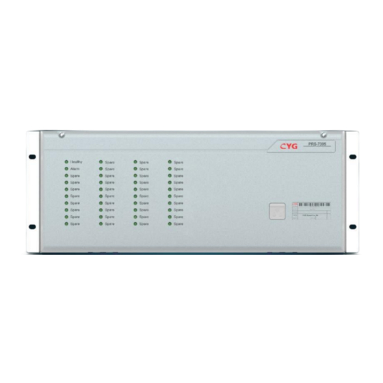
DISP Supply To PD and Communication Keypad For all modules Figure 6.1.1 Hardware Frame of PRS-7395 The following figures show the front panel and the rear panel of PRS-7395. PRS-7395 Merging and Control Unit Healthy SW3 Open SW5 Close Alarm... - Page 36 SR6313 SR6330 SR6330 SR6330 PWR+ PWR- · Figure 6.1.3 Real Panel of PRS-7395 The following figures show the front panel and the rear panel of PRS-7395(phase separation). PRS-7395 Merging and Control Unit Healthy PHC Open SW7 Open CtrError Alarm Alarm...
-
Page 37: Hardware Module
IED Hardware 6.2 Hardware Module The PRS-7395 is comprised of randomly coordinated modules, except that a few particular modules, e.g., PWR module, CPU module and HMI module, cannot be replaced in the whole device. The other modules, including TF (current or voltage transformer) module and IO (input and output) module, can be flexibly configured and then placed in the remained slots. -
Page 38: Main Cpu Module
The main CPU module, containing powerful microchip processors and some necessary electronic accessories, is the core part of this relay. This powerful processor executes all the functions of the relay and conduct the commands, including data acquisition, data processing, data communication, display management, time synchronization, and other functionalities. PRS-7395... -
Page 39: Binary Input Module
All the BI terminals can be used as general purpose binary inputs or special purpose (protection function or control function) binary inputs. All the BI signals can be sent to the monitoring system through protection or BCU. The frame of the BI module terminal is described as below. PRS-7395... - Page 40 COM2- COM1- Figure 6.4.1 Frame of BI Terminal The specific terminal definition of the connector is described as below. Table 6-3 Terminal Definition and Description of BI Module Name Description BI01~BI26 Binary input 1~26 COM1-、COM2- BI signals common terminal PRS-7395...
-
Page 41: Binary Output
BO15+ BO07+ BO07- BO15- BO16+ BO08+ BO16- BO08- Figure 6.5.1 Frame of BO Terminal The terminal definition of the BO module is described as below. Table 6-4 Terminal Definition and Description of BO Module Name Description BO01~BO16 Binary output1~16 PRS-7395... -
Page 42: Binary Input/Output Module
BI05 BO03+ BO03- BI06 BO04+ BI07 BI08 BO04- BO05+ BI09 BO05- BI10 BO06+ BI11 BO06- BI12 BO07+ BI13 BI14 BO07- BI15 COM- Figure 6.6.1 Frame of IO Terminal The terminal definition of the IO module is described as below. PRS-7395... -
Page 43: Bi/Dc Input Module
BI/DC module includes 16 optically isolated binary inputs and 2 DC inputs, DC such as temperature sensor, humidity sensor, etc. The supported interface modes include 0-5V signal or 4-20mA signal. The terminal definition of the BI/DC module is described as below. PRS-7395... - Page 44 2+ signal 2- BI01 BI10 BI11 BI02 BI12 BI03 BI04 BI13 BI14 BI05 BI06 BI15 BI07 BI16 BI08 BI09 COM2- COM1- Figure 6.7.1 Frame of BI/DC Terminal The terminal definition of the BI/DC module is described as below. PRS-7395...
-
Page 45: Transformer Module
The frame of two transformer modules of different specifications are shown below. SR6110 The SR6110 transformer module consists of 5 current channels and 1 synchronous voltage channels. The terminal definition is described as below. PRS-7395... - Page 46 Protection Current Phase C Synchronous voltage Zero-sequence current Gap current SR6150 The SR6150 transformer module consists of 3 protection voltage channels, 1 zero-sequence voltage, 3 measurement voltage and 3 measurement current channels. The terminal definition is described as below. PRS-7395...
- Page 47 Description Protection Voltage Phase A Protection Voltage Phase B Protection Voltage Phase C Zero-sequence voltage Measurement Voltage Phase A Measurement Voltage Phase B Measurement Voltage Phase C Measurement current Phase A Measurement current Phase B Measurement current Phase C PRS-7395...
-
Page 48: Communication Protocol
7.2.1.2 Ethernet Communication protocol Ethernet communication protocols are supported by the device including: IEC61850 etc. For more details about these communication protocols, see the correlative standards. 7.3 Network Topology 7.3.1 PRP Topology This network topology is supported by the device. PRS-7395... -
Page 49: Iec61850 Protocol
IEC 61850 implementation obtain this document set. 7.4.2 Communication Profiles The PRS-7000 series relay supports IEC 61850 server services over TCP/IP communication protocol stacks. The TCP/IP profile requires the PRS-7000 series to have an IP address to establish communications. PRS-7395... - Page 50 The GOOSE receiving buffer zone of the unit receives the new GOOSE messages, after a strict check of the relevant parameters of GOOSE messages, the receiving side first compares if the StNum (status number) of the newly received frame and that in the GOOSE message of the PRS-7395...
-
Page 51: Data Set And Control Block
The report control block performs the control of report submission via a series of attribute configurations. Specifically, it has the following important attributes: PRS-7395... - Page 52 Trigger option, used to filter the conditions for sending reports. PRS-7000 supports the following trigger options: - Bit 1: Data change - Bit 2: Quality change - Bit 3: Data updating (the service follow-up of Ed2) - Bit 4: Completeness period - Bit 5: Total call IntgPd PRS-7395...
-
Page 53: Logic Nodes And Data Modeling
(BRCB and URCB) and log control block (LCB); some common data objects are modeled in this node, such as Loc, to represent the local and remote operation enabling of the unit, and the based function VEBI and common settings; some data objects represent the meaning of PRS-7395... - Page 54 The PRS-7000 series unit uses the above common data types, and instantiate the specific data objects according to the need of application functions, to meet the need of application functions. There are the following common data objects in all logic nodes (except for LPHD): PRS-7395...
- Page 55 The performance of the logic node, representing the current performance status of the logic node, the value of the same Mod is read-only and cannot be modified. Health Health status, it reflects the status of the relevant software and hardware of the logic node. NamPlt The name plate of the logic node PRS-7395...
-
Page 56: Commissioning
Therefore, be sure to fully comply with all warnings and cautions. 8.2.2 Safety Identification Examples For the various safety instructions given in the previous section, the following are examples 8.2.2.1 Warning Signs PRS-7395... - Page 57 Regardless of operating conditions, remember to connect the device to the earth, also needed for special occasions such as testing, demonstrating and off-line configuration on the desk. Operation of the device without proper earthing may damage the device and the measuring circuit and may also cause an injuring accident. PRS-7395...
-
Page 58: Commission Tools
The indicators can refer to the commissioning record of the device. Attention! Disconnect the external AC circuit of the cubicle before the test to avoid causing a safety accident, which will cause serious damage to the construction workers on site. PRS-7395... -
Page 59: Product Checks
500V. Insulation should meet the following requirements: Device independent circuit and exposed conductive parts, 500V megger insulation resistance measured value should be no less than 100MΩ; PRS-7395... -
Page 60: External Wiring Check
• Timers test • Metering and recording test • Conjunctive tests The tests are performed after the relay is connected with the primary equipment and other external equipment. • On load test. • Phase sequence check and polarity check. PRS-7395... -
Page 61: With The Relay Energized
When abnormal condition reset, the “ALARM” LED extinguishes. 8.6.2.2 Test the Other LEDs Test the other LEDs according to the configuration of the LEDs (through the PRS IED Studio software). If the conditions which can turn on the selected LED are satisfied, the selected LED will PRS-7395... -
Page 62: Test The Ac Current Circuit
. Protection voltage measurement accuracy requirement shall be no higher than 1.5%. Measuring voltage measurement accuracy requirement shall be no higher than 0.25%However an additional allowance must be made for the accuracy of the test equipment being used. PRS-7395... -
Page 63: Test The Binary Inputs
The corresponding relay contact of the device shall be operated with the corresponding action or alarm signal. 8.6.7 Function Checks The purpose of this experiment is to verify the correctness of the logic. For details on how to implement the logic function, refer to "Operation Theory" PRS-7395... -
Page 64: On-Load Checks
Tighten the secondary circuit terminals, especially for the current terminals, circuit breaker closing and opening, operating power supply circuit. Ensure that all records have been cleared and LED’s has been reset before leaving the device. Ensure that the device has been restored to service. PRS-7395... -
Page 65: Installation
Always store and ship the electronic boards in their original packing. Place electronic parts in electrostatic screened packing materials. 9.3 Checking the Shipment Vehicles, trains, ships and all other means of transport are available, but to prevent snow and rain, shock, impact and collision, to ensure product packaging integrity. PRS-7395... -
Page 66: Material And Tools Required
Visually inspect all the material when unpacking it. When there is evidence of transport damage, lodge a claim immediately in writing with the last carrier and notify the nearest CYG SUNRI CO., LTD.Company or agent. Unpacking and checking procedures 1. -
Page 67: Mechanical Installation
Installation as a whole, rear wiring. The current/ voltage connector structure are in the same size, and can be expanded, combined flexibly. Installation hole size as below. Attention! It is necessary to leave enough space top and bottom of the cut-out in the cubicle for heat emission of this relay. PRS-7395... - Page 68 Installation PRS-7395...
-
Page 69: Electrical Installation And Wiring
If the wire length is not enough during the process of wiring or rewiring, the worker must replace it. There should be no excess wire in the slot. If it is required to remove the wire, the whole wire must be completely removed. PRS-7395... -
Page 70: Grounding
When using electrical connections between the protection device and the communication device, or point-to-point electrical connections between the two protection devices, it is important to install the cables carefully. Due to the low electrical level of communication signals, the factors susceptible PRS-7395... -
Page 71: Installation Check
Hardware and software version information is available on the device label. After the device is powered on, the software version can also be checked through the LCD interface. 9.8.3 Device start if confirm that the wiring is correct during the installation check, you can supply device with power and start it. PRS-7395... - Page 72 1 minute. The "HEALTHY" indicator lights up when the unit starts up normally. If a fault is detected during the startup procedure, the "ALARM" indicator is lit and the internal fault code, alarm information can be checked via LEDs. PRS-7395...
-
Page 73: Maintenance
Check whether the device has obvious physical fault If you can find a clear physical fault point of the device, please contact CYG for repair or replacement Confirm the scope of the fault ... -
Page 74: Software Failure
Maintenance If it is determined that the fault belongs to the relay device, please contact CYG for repair or replacement 10.3.2 Software Failure Check whether the hardware is in trouble or not according to the device alarm signal. Try to restart the device and check if the fault is recoverable if possible. -
Page 75: Decommissioning And Disposal
When removing and replacing modules, it is best to use the label in the chassis as a indicator, so as to make sure each module is installed in the proper slot. PRS-7395... - Page 77 Decommissioning and Disposal NOTICE! Strictly observe all local and national regulations when disposing of the device. PRS-7395...
-
Page 79: Manual Version History
In the current version of the instruction manual, several descriptions on existing features have been modified. Table 12-1 Manual version and modification history records Manual Version Software Date Description of change Source Version Beta 1.00 1.00 2023-03-25 Form the original manual. PRS-7395...
Need help?
Do you have a question about the PRS-7395 and is the answer not in the manual?
Questions and answers