
Subscribe to Our Youtube Channel
Summary of Contents for Boston Scientific LithoVue M0067913500
- Page 1 LithoVue System Workstation ™ en User’s Manual ����������������������������������������������������������������������������������������������4 Black (K) ∆E ≤5.0...
-
Page 2: Table Of Contents
TABLE OF CONTENTS 1 INTRODUCTION ��������������������������������������������������������������������������������������������������������������������������������������������������������������� 4 1.1 Safe Use Requires Reading the User’s Manual ....................6 1.2 Post-Procedure ..............................6 2 CLINICAL INFORMATION ����������������������������������������������������������������������������������������������������������������������������������������������� 6 2.1 Indications for Use and Intended Use ........................ 6 2.2 Contraindications ..............................6 2.3 Clinical Benefits ..............................6 2.4 User Training, Knowledge, and Skills ......................... - Page 3 7.6 Patient Counseling ............................... 41 8 SERVICE AND WARRANTY ������������������������������������������������������������������������������������������������������������������������������������������ 41 8.1 Warranty ................................41 8.2 Obtaining Warranty Service from Boston Scientific Corporation ............... 41 9 ELECTROMAGNETIC COMPATIBILITY (EMC) REQUIREMENTS ���������������������������������������������������������������������������� 41 9.1 Guidance and Manufacturer’s Declaration-Electromagnetic Emissions ........... 41 9.2 Guidance and Manufacturer’s Declaration –...
-
Page 4: Introduction
ONLY Caution: Federal Law (USA) restricts this device to sale by or on the order of a physician. 1 Introduction This user’s manual describes how to use, maintain, and troubleshoot the LithoVue System (see Figure 1�1). The LithoVue System is a software-controlled digital flexible ureteroscope system that consists of the LithoVue System Workstation (Touch PC and Cart) and the LithoVue Single-Use Digital Flexible Ureteroscope (sterile, single-use disposable). - Page 5 Figure 1�1 – LithoVue System Main Operating User Supplied Screen Monitor DVI Cable Power Cord Flexscope Connector Cable Plug Receptacle AC Power Cord Connector Cable LithoVue Flexscope System Workstation The System Workstation does the following: (a) Provides power for the illuminating LED and video image hardware in the LithoVue Flexscope. (b) Receives video signals from the LithoVue Flexscope and processes the images for display on the System Workstation screen or on a user-supplied monitor, if connected.
-
Page 6: Safe Use Requires Reading The User's Manual
Follow all instructions, cautions, and warnings provided with all products and equipment to be used in conjunction with the LithoVue System to avoid any possible hazards due to device incompatibility. If the instructions are unclear to you, contact Boston Scientific for assistance, using the information found in Section 8 “Service and Warranty”. -
Page 7: Warnings
Only physicians who have ureteroscopic, diagnostic, and therapeutic training should use the LithoVue System. A thorough understanding of the techniques, principles, clinical applications, and risks associated with endoscopic urinary tract procedures is necessary before using this device. This includes, but is not limited to devices used in laser lithotripsy, administration of irrigation/contrast, and use of procedural accessories such as baskets/forceps, access sheaths, renal sheaths, guidewires, and antiretropulsion devices. -
Page 8: Precautions
No modification of this equipment is allowed. Do not attempt to repair or alter any components/parts of the LithoVue System Workstation. The LithoVue System Workstation contains no operator-serviceable components. All repairs and servicing are to be performed only by authorized Boston Scientific service personnel. See Section 8 “Service and Warranty” for additional information. -
Page 9: Adverse Events
System Workstation. • During assembly and before each use, inspect all components for damage. Do not use a component if it appears damaged. Contact Boston Scientific for service using the information found in Section 8 “Service and Warranty”. 2�7 ADVERSE EVENTS Possible complications include, but may not be limited to: •... -
Page 10: How Supplied
Do not use if labeling is incomplete or illegible� CAUTION: Inspect the components for damage� Do not use a component if it appears damaged� Contact Boston Scientific for service� 3�1 SYSTEM WORKSTATION COMPONENTS The LithoVue System Workstation is shipped in a cardboard shipping crate. Inside the shipping crate, the components of the System Workstation are packaged separately, as noted in Figure 3�1. -
Page 11: System Workstation Assembly
CAUTION: Do not attempt to repair or alter any components/parts of the LithoVue System Workstation� The LithoVue Touch PC contains no operator-serviceable components� All repairs, upgrades and servicing are to be performed only by authorized Boston Scientific service personnel� See Section 8 “Service and Warranty” for additional information�... -
Page 12: Attaching The Touch Pc Mounting Plate To The Cart Post
Figure 3�2 – Attaching the Cart Post to the Cart Base Cart Post Cart Base 5/16" flat washer, 5/16" split lock washer, and hex head cap screw 5. Return the Cart to the upright position and confirm that the three caster locks are pressed down to lock the Cart into position. -
Page 13: Attaching The Cart Handle
Figure 3�3 – Installing the Touch PC Mounting Plate Touch PC Mounting Plate (3) No. 10-32 x 9/16" Mounting Screws Top of Cart Post Attaching the Cart Handle 1. Separate the two pieces of the Cart Handle by using a Phillips-head screwdriver to remove the (2) pre- installed screws. -
Page 14: Attaching The Power Transformer Bracket
Figure 3�5 – Proper Placement of the Cart Handle Attaching the Power Transformer Bracket 1. Attach the Cord Wrap Hook and Power Transformer Bracket’s Clamping Blocks together around the Cart Post approximately 40 cm (16") from the Cart Base. Ensure the Velcro straps for the Power Transformer are facing forward (same direction as the Touch PC Mount). - Page 15 Figure 3�6 – Touch PC Tilt Adjustment Lever Tilt Adjustment Lever 4. Tighten the Tilt Adjustment Lever to prevent movement of the mounting plate during assembly. 5. Using a Phillips-head screwdriver, install two of the four M4 x 10 mm Mounting Screws in the two upper holes of the inner set of the Touch PC’s VESA-mounting holes (See Figure 3�7).
- Page 16 Figure 3�8 – Installing the Touch PC Mounting Plate Inner VESA Mounting Hole Set 8. Tighten the top two M4 x 10 mm Mounting Screws holding the Touch PC to the mounting plate. 9. Install the Power Transformer into the Power Transformer Bracket with the power indication LED visible and AC power cord connection facing down and hold it in place using the Velcro straps.
-
Page 17: Cart Adjustment
Figure 3�10 – Installing the Power Transformer Bracket Power Cord Wrap Hook Transformer Power Transformer Holder with Velcro Straps Clamping Blocks Cart Adjustment The Cart is equipped with (2) adjustment mechanisms, one for adjusting the Touch PC’s height and another for adjusting the Touch PC’s tilt. -
Page 18: Adjusting Touch Pc Height
Adjusting Touch PC Height CAUTION: The Touch PC Cart Post operates by pneumatic pressure and will travel upward when disengaged� Ensure that nothing obstructs upward travel before turning the Height Adjustment Knob� Grasp the Touch PC using the side handholds to control the upward travel of the Touch PC when the Height Adjustment Knob is loosened�... - Page 19 Figure 3�13 – Front Panel Power Button Power Button The System Workstation displays the boot screen (see Figure 3�14). Figure 3�14 – Boot Screen 4. The System Workstation will display the LithoVue Flexscope disconnected message screen (see Figure 3�15) in the image display area. Once this image has been displayed, the System Workstation is functioning correctly and is now ready for use.
-
Page 20: Connecting An External Monitor Or Dvi Switcher With The Dvi Cable
Connecting an External Monitor or DVI Switcher with the DVI Cable If desired, you can display the live video image on an external DVI-compatible monitor or split the image signal using a DVI switcher by following these steps: 1. Confirm that the external monitor and/or DVI switcher meets the specifications described in Section 3.4 “System Workstation Device - Accessory Compatibility”. -
Page 21: Specifications And Device Compatibility
3�4 SPECIFICATIONS AND DEVICE COMPATIBILITY Electrical Table 3�2 Power Transformer and Power Cord Specifications CAUTION: The Power Cords and Power Transformer must be compatible with the LithoVue System� A compatible Power Cord and Power Transformer are provided with each System Workstation for this purpose�... -
Page 22: Illumination Output (Nominal)
5:4 and 16:9. The LithoVue System has been tested and shown to be compatible with the NDS Radiance SC-SX19-A1511. Software Information The software revision level is controlled by Boston Scientific. The current revision level is provided below the BSC logo on the System Workstation display. Black (K) ∆E ≤5.0... -
Page 23: Lithovue System
4 LithoVue System 4�1 SYSTEM WORKSTATION FEATURES AND USER INTERFACE System Workstation Front Panel Features and User Interface The System Workstation Front Panel (see Figure 4�2) has the following features: • Main Operating Screen – A color liquid crystal touch-screen display (LCD) provides the live video image and graphical user interface (GUI). -
Page 24: System Workstation Rear Panel Features
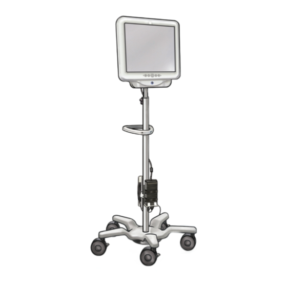
System Workstation Rear Panel Features The rear panel includes these features: • DVI Output Connector — (See Figure 4�3) Video output connector for compatible DVI-capable monitors or a DVI Switcher. For more information regarding compatible monitors and DVI Switchers, see Section 3.4 “System Workstation Device - Accessory Compatibility”. - Page 25 Figure 4�4 – Cart Features Tilt Adjustment Lever Height Adjustment Knob Handle Cord Wrap Hook Power Transformer Bracket Casters (3 Locking) Black (K) ∆E ≤5.0...
-
Page 26: Main Operating Screen
4�3 MAIN OPERATING SCREEN Main Operating Screen Features The main operating screen (see Figure 4�5) includes the features described in the sections below. NOTE: On-screen buttons are activated by a finger-press. Figure 4�5 – Main Operating Screen Live Video Image/ Message Screen Display Area Light On/Off... -
Page 27: Image Brightness Control Buttons
Light On after a button press After a short period of time, the Light On/Off button will then change to display the default Light On indicator noted above. Image Brightness Control Buttons When the light is on, pressing the button increases the image brightness. Pressing the button decreases the image brightness. -
Page 28: Controls Swap Button
When there are zero minutes remaining, the Time Remaining Indicator will disappear and the “Use Time Exceeded” message screen will appear in the image display. See Section 4.3 “Message Screens” for more information on the use time exceeded message screen. If additional time is needed for the procedure, after the “Use Time Exceeded”... -
Page 29: Live Video Image Display Area
Figure 4�6b – Main Operating Screen – Controls on Right Live Video Image Display Area This is the area where the live video image is displayed. The live video image area is also used to display system message screens in lieu of the video image. For more information on message screens, see Section 4.3 “Message Screens”. -
Page 30: System Operation
5 System Operation 5�1 STARTING THE SYSTEM WORKSTATION Follow the steps below to start the System Workstation: 1. Plug the System Workstation into the hospital electrical outlet. If there is a switch on the Power Transformer (MPU101-105), then ensure the switch is turned on. The green LED on the Power Transformer will light when the Power Transformer is on. - Page 31 5. Plug the LithoVue Flexscope Cable into the Workstation Receptacle on the front panel of the System Workstation by lining up the triangle on the Connector Cable’s Plug with the triangle on the front panel of the System Workstation. NOTE: The LithoVue Flexscope may be plugged in before the System Workstation has been powered on.
-
Page 32: Checking The Quality Of The Video Image
Figure 5�5 – LithoVue System displaying final high quality live video image 5�2 CHECKING THE QUALITY OF THE VIDEO IMAGE Before performing a procedure, hold the distal tip of the LithoVue Flexscope close to an object (about the same distance as the width of the shaft) and ensure the video monitor displays a clear, sharply focused, high- quality image. - Page 33 CAUTION: The Touch PC Cart Post operates by pneumatic pressure and will travel upward when disengaged� Ensure that nothing obstructs upward travel before turning the Height Adjustment Knob� Grasp the Touch PC using the side handholds to control the upward travel of the Touch PC when the Height Adjustment Knob is loosened�...
-
Page 34: Safely Shutting Down The System Workstation
CAUTION: Do not remove the Flexscope Cable from the System Workstation by pulling on the cable� Improper removal of the Flexscope Cable may damage the System Workstation� Dispose of the LithoVue Flexscope in accordance with hospital, administrative and/or local government policy� 5�5 SAFELY SHUTTING DOWN THE SYSTEM WORKSTATION Follow these steps to shut down the System Workstation at the end of a procedure or during a procedure: 1. -
Page 35: Maintenance, Service And Replacement Parts
7 Troubleshooting Most operating problems are easily resolved. If the LithoVue System does not operate as expected, try to resolve the problem using the instructions contained in this section before contacting Boston Scientific for technical support. This section contains directions on how to isolate the System Workstation from the mains power supply, as well as troubleshooting instructions for the following situations: 1. -
Page 36: Loss Of Articulation Control On The Lithovue Flexscope
Dispose of the LithoVue Flexscope in accordance with hospital, administrative and/or local government policy and use another scope to complete the procedure. If the image issues still do not resolve after connection of a new LithoVue Flexscope, contact Boston Scientific using the information found in Section 8 “Service and Warranty”. - Page 37 Figure 7�1 – LithoVue Flexscope Articulation Lever Articulation Section Connector Cable and Plug Handle Accessory Access Port Distal Tip Irrigation Port Strain Relief Flexible Shaft b. Advance the guidewire slowly, observing the live video image for initial entry of the guidewire into the field of view.
-
Page 38: System Workstation Power Loss
1. Press the Power button until the System Workstation shuts down. 2. Press the Power button to restart the System Workstation. 3. If the System Workstation fails to start, contact Boston Scientific using the information found in Section 8 “Service and Warranty” for System Workstation service. - Page 39 If User Message remains after a repeated connection, proceed to step below. System Workstation internal Reboot the System Workstation. If the problem still hardware communication exists, contact Boston Scientific for support. failure. LithoVue Flexscope Use Time Exceeded icon is displayed in the video field.
- Page 40 Boot problem. restart the System Workstation. If problem reoccurs, illuminated, but the boot contact Boston Scientific using the information found screen does not display� in Section 8 “Service and Warranty”. Illumination light off. Press the Light On/Off button to turn illumination on.
-
Page 41: Patient Counseling
All transportation and insurance charges and risk of loss are the responsibility of the customer and must be prepaid. A purchase order must be issued to Boston Scientific Corporation to cover all transportation and insurance charges for return shipment after service. -
Page 42: Guidance And Manufacturer's Declaration - Immunity All Equipment And Systems
9�2 GUIDANCE AND MANUFACTURER’S DECLARATION – IMMUNITY ALL EQUIPMENT AND SYSTEMS The LithoVue System is intended for use in the electromagnetic environment specified below (Table 9.2). You should ensure the operating environment meets these requirements before using the System Workstation. Table 9�2 Acceptable environment for operation of the System Workstation IEC 60601 Compliance... -
Page 43: Guidance And Manufacturer's Declaration - Emissions And Equipment And Systems
9�3 GUIDANCE AND MANUFACTURER’S DECLARATION – EMISSIONS AND EQUIPMENT AND SYSTEMS THAT ARE NOT LIFE-SUPPORTING The LithoVue System is intended for use in the electromagnetic environment specified below (Table 9.3). You should ensure the operating environment meets these requirements before using the System Workstation. Table 9�3 Guidance and manufacturer’s declaration –... -
Page 44: Recommended Separation Distance Of Other Equipment
9�4 RECOMMENDED SEPARATION DISTANCE OF OTHER EQUIPMENT The LithoVue System is intended for use in an electromagnetic environment in which radiated RF disturbances are controlled. You should help prevent electromagnetic interference by maintaining a minimum distance between portable and mobile RF communications equipment (transmitters) and the LithoVue System as recommended below, according to the maximum output power of the communications equipment (Table 9.4). - Page 45 The following is a trademark of Boston Scientific Corporation or its affiliates: LithoVue All other trademarks are the property of their respective owners. Black (K) ∆E ≤5.0...
- Page 46 Legal Manufacturer Boston Scientific Corporation 300 Boston Scientific Way Marlborough, MA 01752 USA Customer Service 888-272-1001 www.IFU-BSCI.com © 2023 Boston Scientific Corporation or its affiliates. All rights reserved. 2023-06 51628022-01 Black (K) ∆E ≤5.0...
Need help?
Do you have a question about the LithoVue M0067913500 and is the answer not in the manual?
Questions and answers