Table of Contents
Advertisement
Quick Links
Advertisement
Table of Contents

Related Manuals for KEHUA TECH iStoragE Series

Summary of Contents for KEHUA TECH iStoragE Series
- Page 1 Series Energy Storage System Installation Guide...
-
Page 2: Product Intro
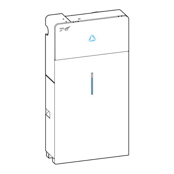
Product Intro Suitable model: Inverter: ·iStoragE 3600 ·iStoragE 5000 ·iStoragE 6000 Battery: ·StoragE B8 NOTE If the floor of installation site is uneven, please use gaskets to keep the bottom of battery pack level. 1.1 Appearance 1.2 LED Indicator (Inverter) Status LED display Illustration... -
Page 3: Installation Preparation
1.3 LED Indicator (Battery pack) LED display Status Illustration SOC≤5% The first line of the LED indicator flashes every 10s. The first line of the LED indicator is always on. When the SOC is less than 30% and the battery is being charged, 5%≤SOC≤30% the first line of the LED indicator will flash every 3s. -
Page 4: Installation Clearance
Avoid direct sunlight Avoid rain Avoid snow 2.2 Installation Clearance ≥100 Unit: mm... -
Page 5: Installation Method
2.3 Installation Method Vertically Obliquely forwards Obliquely backwards Flat ≤15° 90° Single Battery Installation WARNING The battery is very heavy and needs to be transported and installed by auxiliary tools. There is a risk of injury if the battery pack is not handled correctly when transporting the battery, attaching the battery pack to the wall bracket or removing it from the wall bracket. - Page 6 Step2 Determine the installation site based on the inverter size and installation clearance. Step3 Mark the drilling position. Drill two holes (Diameter: Φ10mm, depth: 70mm). Step4 Step5 Attach the battery wall bracket to the wall using the screws.
- Page 7 Unit: mm Step6 Install the battery support rack with two screws M5. Rear Step7 Place the battery against the wall, align the holes at the battery side to the screw holes of the wall bracket. Step8 Fasten the battery pack. NOTE If the floor of installation site is uneven, please use gaskets to keep the bottom of battery pack level.
-
Page 8: Column Installation
More Batteries Installation Column installation CAUTION You can install extra batteries up to 6 batteries in a system. Please install extra batteries one by one, also batteries can be stacked up to two batteries per column. After the battery pack is installed, clean up the excess wires, foam, cardboard boxes and other useless items. -
Page 9: Stack Installation
Step5 Install extra batteries one by one, keep the distance between the batteries about 300mm. Stack installation Step1 Repeat ingle battery installation step1~step6. Step2 Tighten the battery cover plate of each battery with three screws M4. NOTE If the battery directly connected to the inverter, it doesn't need the battery cover plate. Step3 Place the battery against the wall, align the holes at the battery side to the screw holes of the wall bracket. - Page 10 Step5 After install the single battery, then lock the four screws M6 on top of the below battery pack. Step6 Place the battery positioning paper against the wall and the bottom with notch against the below battery pack, and mark the positions of the two drill holes.
- Page 11 Step7 Repeat ingle battery installation step4~step6. Step8 Place the battery against the wall, the bottom limit holes of the upper battery pack should match the screw on the top of the below battery pack. Step9 Tighten the wall bracket and the battery pack with screw M5. Step10 Install extra batteries one by one, keep the distance between the batteries about 300mm.
-
Page 12: Inverter Installation
⑤ ⑥ Inverter Installation Step1 Repeat ingle battery installation step1~step8. Step2 Align the bottom of the inverter's positioning paper with the notch of the battery top. Step3 Mark the positions of the drill holes on the paper plate. - Page 13 Step4 Cover the top of the battery with plastic bag and drill seven holes (Φ8, depth range: 40~45mm), insert seven expansion plugs (8*40) into the drill holes. 40-45mm Step5 Attach the wall bracket to the wall using seven M5 self-tapping screws with the tool of screwdriver.
-
Page 14: Electrical Connection
Electrical Connection 6.1 Bottom layout ① Meter1/ Meter2 ② DRM ③ BMS ④ Parall1/Parall2 (reserved) ⑤ BATT+/BATT- ⑥ Grounding port ⑩ ⑦ WIFI port ⑧ Explosion-proof valve ⑪ ⑨ Grid output terminal ⑩ Backup output terminal ⑫ ⑪ DC input terminal ⑫... -
Page 15: Specification
Isolator, Overcurrent Protection Device and RCD Specification Specification Component Scope of supply Integrated in the inverter (optional) PV DC switch Circuit breaker Purchased by the installer 32A for 3600VA, 50A for 5000VA, 63A for 6000VA for AC Circuit breaker Purchased by the installer 20A for 3600VA, 25A for 5000VA, 32A for 6000VA for backup Type B 30mA, <0.3S... - Page 16 DC Input (PV) Connection CAUTION ·When installation, it must use the equipped DC terminals to avoid inverter damage. ·It is recommended to use independent switch for each PV input, and before connecting, the switches must be off. We suggest to use the special DC switch (rated voltage is 600V, rated current is more than 20A). ·Switch off the DC switch and external DC switches before connecting the PV array.
- Page 17 Step2 Measure the voltage and check if the positive and negative is connected properly and if the voltage within the input range of the inverter. 888.8 Measure the voltage of PV string<580V Step3 Connect the PV connectors (black). DC Input (Battery) Connection Connect the BAT connectors (blue).
- Page 18 Battery pack expansion: Step1 Connect the power cables and BMS communication cable between the two batteries. Column installation Stack installation Step2 Install the terminal resistance to any one of COM ports of the first battery.
-
Page 19: Ac Output Connection
AC Output Connection CAUTION ·It's forbidden that several inverters shares an AC switch. ·It's forbidden to connect with load between inverter and AC switch. To ensure the inverter can be disconnected with load safely, we suggest equipping independent dipolar switch (as below) for each inverter to protect the inverter. Model AC input specification (GRID) AC output specification (BACKUP) - Page 20 Step3 Unscrew the lock nut, lead the live wire, neutral wire go through the lock nut, and then connect them to the corresponding port of AC terminal (draw the live wire and neutral wire connected to grid through the two magnetic rings). Step4 Tighten terminals one by one with tool of screwdriver.
- Page 21 6.8 WIFI Connection WIFI communication connection. Communication Port Connection Communication ports include DRM port, Meter port and BMS port, they all adopt RJ45 plug to connect. The pin definition of RJ45 plug is as shown in below. Meter PIN definition: RJ45 interface RJ45 plug PIN definition of RJ45 plug:...
- Page 22 BMS port: BMS communication port is used to connect the COM port of battery pack through battery communication wire. Meter port: Meter communication port is used to communicate with smart meter to achieve zero-export. The connection between smart meter and inverter and grid is as shown in below. NOTE For the actual wiring of the smart meter, see the diagram on the right side of the meter.
- Page 23 PV Inverter Smart Smart Meter Meter Single phase + Single phase L1 L2 L3 L1 L2 L3 N PE N PE Smart Meter 13 14 16 17 19 21 24 25 Three-phase...
- Page 24 L1 L2 L3 N PE L1 L2 L3 N PE PV Inverter Smart Smart Meter Meter 13 14 16 17 19 21 24 25 Three-phase + Single phase Insert the communication port. 6.10 Inverter wiring cover plate installation Step1 Tighten the wiring cover plate.
-
Page 25: Start-Up Operation
Step2 Pad the gasket. Startup Operation Step1 Check whether the PV, battery and grid wiring correct. Step2 Switch on the battery breaker, long press the BAT. ON/OFF button about 5S. After about 30S, the indicator will be on. Step3 Switch on the DC switch. Step4 Download the APP and do WIFI configuration:... - Page 26 Download the APP: APPSTORE: https://apps. apple. com/cn/app/wisesolar-plus/id1510470362 GOOGLE PLAY: https://play. google. com/store/apps/details?id=com. kehua. wisesolarpro WIFI configuration: Operation guide: https://energy. kehua. com/quickStart Step5 Build plant a fter registering and logging in...
- Page 27 Step6 Select standard type. In the "Basic parameter setting" item of "Control" page, query or select national standard in the "Standard type" , such as Australia Region A, B, C, New zealand. Step7 Set the inverter function via APP. The mode can be set to time of use mode, backup mode, self consumption mode, energy scheduling mode and external control mode.
- Page 28 Backup mode setting Choose "Disable" in "External control mode ". Choose "Backup mode "in "Work mode ". Self consumption mode setting Choose "Disable" in "External control mode ". Choose "Self consumption" in "Work mode ". Energy scheduling mode setting Choose "Disable"...
- Page 29 External control mode setting Choose "Enable" in "External control mode". Choose "Battery control first" or "Grid control first". Set the corresponding time period. Step8 Perform battery related setting and basic parameter setting.
- Page 30 Step9 About 60s, the inverter will generate power normally. LED is always on. Step10 Working status can be queried on the APP. Step11 When the DC and AC supply power normally, the inverter will prepare to start, 60s later, the system is operating normally, or check the insulation impedance.
- Page 31 XIAMEN KEHUA DIGITAL ENERGY TECH CO., LTD. ADD: Room 208-38, Hengye Building, No. 100 Xiangxing Road, Torch High-tech Zone (Xiang an) Industrial Zone, Xiamen,China (361000) Technical Support TEL: 0592-5160516 (8 lines) FAX: 0592-5162166 4402-04074 002 Http://www.kehua.com...
Need help?
Do you have a question about the iStoragE Series and is the answer not in the manual?
Questions and answers