Table of Contents
Advertisement
Available languages
Available languages
Quick Links
PE - DE
VCPE029 09
ITALIANO
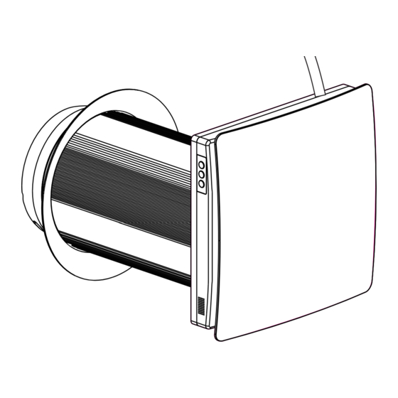
UNITA' DI VENTILAZIONE MECCANICA CONTROLLATA
ENGLISH
CONTROLLED MECHANICAL VENTILATION UNIT
DICHIARAZIONE DI CONFORMITÀ UE SEMPLIFICATA
Il fabbricante dichiara che il tipo di apparecchiatura radio a lato è conforme
alla Direttiva 2014/53/UE (RED). Il testo completo della dichiarazione di
conformità UE è disponibile all'indirizzo Internet riportato in etichetta.
SIMPLIFIED EU DECLARATION OF CONFORMITY
The manufacturer declares that the type of radio equipment indicated
below complies with Directive 2014/53/EUE(RED). The full text of the
EU declaration of conformity is available at the address shown on the label.
/2
3
MANUALE D'USO E INSTALLAZIONE
Inquadrare il QR Code per consultare la pagina
del prodotto sul nostro sito e scaricare l'APP.
USER AND INSTALLATION MANUAL
Scan the QR Code to view the product page on
our site and download the APP.
PERRY ELECTRIC Srl
Via Milanese, 11 - 22070 VENIANO (Como) ITALY
www.perry.it
Manufacturer Fabricat,
,
Fabrikant
, Fabbricante, Fabricante:
PERRY ELECTRIC S.r.l.
Via MILANESE, 11 - 22070 VENIANO (Como)
ITALY - www.perry.it
Tel. +39-031-8944.1 Fax +39-031-8365201
http://www.perry.it/it/dichiarazioni.aspx
Type,
Typen
, Tipo:
VMC001WIFI
&
Series, Serie:
V001
Advertisement
Table of Contents

Summary of Contents for Perry Electric VMC001WIFI
- Page 1 VCPE029 09 ITALIANO UNITA' DI VENTILAZIONE MECCANICA CONTROLLATA ENGLISH CONTROLLED MECHANICAL VENTILATION UNIT Manufacturer Fabricat, Fabrikant , Fabbricante, Fabricante: PERRY ELECTRIC S.r.l. Via MILANESE, 11 - 22070 VENIANO (Como) ITALY - www.perry.it Tel. +39-031-8944.1 Fax +39-031-8365201 http://www.perry.it/it/dichiarazioni.aspx Type, Typen , Tipo:...
- Page 2 ITALIANO INDICE Avvertenze pag. 3 Significato dei simboli pag. 3 Avvertenze utilizzo Wi-Fi pag. 5 Avvertenze portata radio pag. 6 Introduzione pag. 7 pag. 7 Contenuto imballo pag. 7 Specifiche tecniche pag. 7 Dimensioni pag. 8 Dati tecnici pag. 8 Design e operativita' pag.
-
Page 3: Significato Dei Simboli
AVVERTENZE Leggere queste istruzioni attentamente prima di installare ed utilizzare il prodotto. Le avvertenze contenute in questo manuale devono essere scrupolosamente seguite. Dopo aver tolto l'imballaggio, assicurarsi dell'integrità dell'apparecchio; in caso di dubbio non utilizzarlo e rivolgersi a personale professionalmente qualificato. Assicurarsi che il proprio impianto domestico sia conforme alle specifiche elettriche del prodotto. -
Page 4: Avvertenze Di Sicurezza
Disconnettere il prodotto dall'alimentazione elettrica prima di ogni operazione di pulizia o manutenzione Il recuperatore deve funzionare all'interno dell'intervallo di temperatura prescritto e non deve essere installato in ambienti esplosivi Assicurarsi che il cavo di alimentazione sia collocato lontano da fonti di calore Per l’installazione occorre prevedere nella rete di alimentazione, conformemente alle regole di installazione, un interruttore onnipolare che consenta la disconnessione completa (distanza... - Page 5 Non danneggiare il cavo di alimentazione. Mantenerlo lontano da fonti di calore. Se il cavo di è danneggiato, deve essere sostituito dal costruttore o dall' assistenza tecnica Assicurarsi che oggetti infiammabili od esplosivi siano posizionati lontani dal prodotto Non aprire il prodotto mentre è in funzione In caso di malfunzionamento spegnere il ventilatore e rivolgersi ad un centro di assistenza tecnica autorizzato Non permettere che il flusso d'aria del prodotto raggiunga...
- Page 6 AVVERTENZE PORTATA RADIO In fase di installazione, occorre tenere conto di alcuni accorgimenti necessari per non limitare o, in alcuni casi, inibire la portata delle onde radio fra Router e i dispositivi connessi. In assenza di ostacoli tra dispositivi e il Router, la portata in “aria libera”...
-
Page 7: Contenuto Dell'imballo
INTRODUZIONE Questo manuale include informazioni sull'utilizzo in sicurezza del prodotto, istruzioni di montaggio e installazione e dati tecnici. Questo recuperatore è stato concepito per consentire un ricambio di aria controllato in appartamenti, ville, hotels, caffè e altri uffici pubblici. Il recuperatore è fornito con uno scambiatore ceramico che consente la fornitura di aria di rinnovo ed estrazione di aria con recupero di energia. -
Page 8: Dimensioni (Mm)
DIMENSIONI (mm) VMC001WIFI 87.87 30.10 250-500 * *600.00 con apposito accessorio DATI TECNICI Velocità 100 ~ 240V 50÷60Hz Alimentazione Potenza assorbita (W) Corrente assorbita (A) 0.019 0.034 0.0533 Portata m³/h (CFM) 48 (28) 54 (32) 60 (35) RPM [min] 1261 Temperatura max trasportata dell'aria -20°C (-4°F) to +50°C (122°F) - Page 9 COMPONENTI Pannello Filtro HEVA Coperchio Base Piastra di montaggio Flangia Motore brushless DC Ventola Condotto interno Separatore Raddrizzatore Filtro Scambiatore di calore Filtro Separatore Condotto esterno Anello di gomma Griglia aria Griglia esterna MODALITÀ D’USO Il prodotto ha tre modi di ventilazione: Modo Fresh Air il prodotto fornisce aria fresca Modo Exhaust il prodotto espelle l'aria dall'ambiente Modo Cycle il prodotto funziona in modo reversibile con recupero di calore e umidità.
-
Page 10: Installazione Del Prodotto
MONTAGGIO E MESSA IN OPERA & LEGGERE IL MANUALE PRIMA DI MONTARE IL VENTILATORE RECUPERATORE. ATTENZIONE! IL PRODOTTO NON DEVE ESSERE INSTALLATO IN LUOGHI IN CUI IL FLUSSO DELL'ARIA POSSA VENIRE IMPEDITO OD OSTACOLATO DA INDUMENTI, TENDE, DRAPPEGGI, PIANTE ECC. CHE RENDENDO IL VENTILATORE RECUPERATORE MENO EFFICIENTE. -
Page 11: Collegamento Elettrico
Far passare attraverso il foro nel muro dall'interno e tirare indietro il condotto in modo che l'anello interno di gomma aderisca al muro esterno. Riempire lo spazio fra il muro ed il condotto sigillando con silicone. Il condotto deve essere coassiale con il foro nel muro. -
Page 12: Descrizione Del Telecomando
IT IT TASTI DI CONTROLLO SUL PRODOTTO Premere tasto - un beep Modalità aria fresca Cambio modalità Premere tasto - due beep Modalità di scarico Premere tasto - tre beep Modalità ciclo Premere tasto - un beep Velocità bassa Cambio velocità Premere tasto - due beep Velocità... - Page 13 ABBINAMENTO DEL TELECOMANDO AL PRODOTTO Sul retro del prodotto, inserire uno spillo nell’apposito foro e premere delicatamente il pulsante (Switch) finché non si sente un "beep". Quindi premere un pulsante qualsiasi sul telecomando fino a quando non si sente un "beep beep".
-
Page 14: Manutenzione
IT IT MANUTENZIONE DISCONNETTERE IL PRODOTTO DALL'ALIMENTAZIONE ELETTRICA 230V~ PRIMA DI OGNI OPERAZIONE DI INSTALLAZIONE E MANUTENZIONE. Per manutenzione del recuperatore si intende una pulizia periodica delle superfici esterne dalla polvere e la pulizia o sostituzione dei filtri. Scambiatore e manutenzione dei filtri Manutenzione Ventilatore (4 volte l’anno). -
Page 15: Ricerca Guasti
ABBINAMENTO CON SMARTPHONE (APP) Per scaricare l’ inquadrare il QR Code a pag. 1 che riporterà alla pagina del prodotto sul nostro sito. Sul retro del prodotto vi è un foro, premere in modo prolungato il tasto sottostante, rilasciare e il prodotto emetterà una serie di segnalazioni acustiche intermittenti. - Page 16 IT IT AVVERTENZE PER LA CONSERVAZIONE ED IL TRASPORTO Conservare il recuperatore nell'imballo originale in un ambiente asciutto che non contenga gas aggressivi o composti chimici che possano provocare corrosione o danneggiamenti. Utilizzare un sollevatore per le operazioni di movimentazione per prevenire eventuali danni causati da cadute o eccessive oscillazioni.
- Page 17 ENGLISH INDEX Safety warnings pag. 18 Symbol legend pag. 18 Wi-Fi warnings pag. 20 Radio range warnings pag. 21 Introduction pag. 22 pag. 22 Delivery set pag. 22 Main technical parameters pag. 22 Overall dimensions pag. 23 Technical data pag. 23 Design and operating pag.
-
Page 18: Safety Warnings
SAFETY WARNINGS Read this manual with attention before installing and operating the product. Follow the safety instructions to avoid any type of damage to the product or to persons. Installation and operation of the product shall be done in accordanceto the present manual and with regulations and Standard present in each country. -
Page 19: Safety Precautions
The product can not be operated outside the temperature range stated in the user's manual or in aggressive or explosive environments Do not position any heating devices or other equipment in close proximity to the product power cable An omnipolar switch with a contact opening distance of 3 mm or higher should be provided for installation. - Page 20 Keep explosive and inflammable products away from the appliance Do not open the operating ventilator In case of unusual sounds, or smoke, disconnect the ventilator from power supply and contaci the service centre Do not let air flow exiting the be directed to the open flame devices WIFI WARNINGS Radio-frequency waves emitted from the Wi-Fi device do...
- Page 21 RADIO RANGE WARNINGS During installation, some precautions must be taken in order not to limit or, in some cases, inhibit the range of the radio waves between the Router and the connected devices. If there are no obstacles between the devices and the Router, the “open air”...
-
Page 22: Delivery Set
INTRODUCTION This user's manual includes technical description operation, installation and mounting guidelines, technical data for the heat recovery ventilator The ventilator is designed to arrange permanent controllable air exchange in apartments, villas, hotels, cafes and other domestic and public buildings.The ventilator is equipped with a ceramic heat exchanger that enables supply of fresh air and extract air with heat energy recovery. -
Page 23: Overall Dimensions (Mm)
OVERALL DIMENSIONS (mm) VMC001WIFI 87.87 30.10 250-500 * *600.00 with special accessory TECHNICAL DATA Speed Voltage 100 ~ 240V 50÷60Hz Ventilator Total Power (W) Max. Ventilator Current (A) 0.019 0.034 0.0533 Max. Air Capacity m³/h (CFM) 48 (28) 54 (32) -
Page 24: Operating Modes
COMPONENTS Panel Noise reduction HEVA Top shell Chassis Mounting plate Round frame DC brushless motor Biade Inner Ducting Separat frame Pre-filter Ceramic Heating Exchange Core Pre-filter Separator frame Outer Ducting Rubber ring Air Clapboard Air cap OPERATING MODES The ventilator has three ventilation modes: Fresh Air Mode the ventilator supplies fresh air Exhaust Mode the ventilator operates in exhaust mode Cycle Mode the ventilator operates in reversible mode with heat and humidity recovery. -
Page 25: Mounting And Set-Up
MOUNTING AND SET-UP & READ THE USER' S MANUAL PRIOR TO MOUNTING THE VENTILATOR. ATTENTION! THE VENTILATOR MUST NOT BE INSTALLED SITES WHERE THE AIR DUCT MAY BE CLOGGED BY THE BUNDS, CURTAINS,DRAPES,PLANTS,ETC,T0PREVENTTHEROOMDUST DEPOSITlON AND ACCUMULATION. ALSO, CURTAINS MIGHT OBSTRUCTNORMALAIRFLOWINTHEROOM, THUSRENDERING VENTlLAlOROPERATIONNOTEFFICENT. -
Page 26: Connection To Power Mains
Through the wall hole from indoor, and pull back the duct to make the inner side rubber ring cling to the outside wall. Fil the gap between the wall and duct with foam glue (Using waterproof sealing glue for the gap dose to indoor to against rainwater). The inner duct should parallel with indoor wall surface. - Page 27 OPERATION BUTTONS ON BOARD Press with a beep Fresh air mode Mode switching Press with two beeps Exhaust mode Press with three beeps Cycle mode Press with a beep Low speed Speed switching Press with two beeps Middle speed Press with three beeps High speed ON/OFF ON/OFF...
- Page 28 MATCHING THE REMOTE CONTROL TO THE PRODUCT On the rear side of the product, insert a pin into the hole and gently press the button (Switch) until you hear a "beep" Then press any button on the remote control until you hear a "beep beep". Active fan indicates successful pairing.
-
Page 29: Maintenance
MAINTENANCE DISCONNECT THE VENTILATOR FROM 230V~ POWER SUPPLY PRIOR TO ANY MAINTENCE OPERATIONS. Maintenance of the ventilator means regular cleaning of the ventilator surfaces of dust and cleaning or replacement of the filters. Regenerator and filter maintenance Fan maintenance (4 times per year). Once per year) Remove the air flow Pull the ventilator to remove. -
Page 30: Troubleshooting
MATCHING WITH SMARTPHONE (APP) For downloading the scan the QR code in pag.1 that will report to product page in our site. On the rear side of the product there is an hole, press the button inside for an extended time, then release the pressure. -
Page 31: Storage And Transportation Rules
STORAGE AND TRANSPORTATION RULES Store the product in the manufacturer originai packing box in a dry storage environment must not contain EN aggressive vapours and chemical mixtures provoking corrosion, insulation and sealing deformation. Use hoist machinery for handling and storage operations to prevent the ventilator damage in consequenceof failing or excessive oscillation. - Page 32 PERRY ELECTRIC Srl Via Milanese, 11 - 22070 VENIANO (Como) ITALY www.perry.it...
Need help?
Do you have a question about the VMC001WIFI and is the answer not in the manual?
Questions and answers