
Summary of Contents for X-TREME STORES XFIT Series
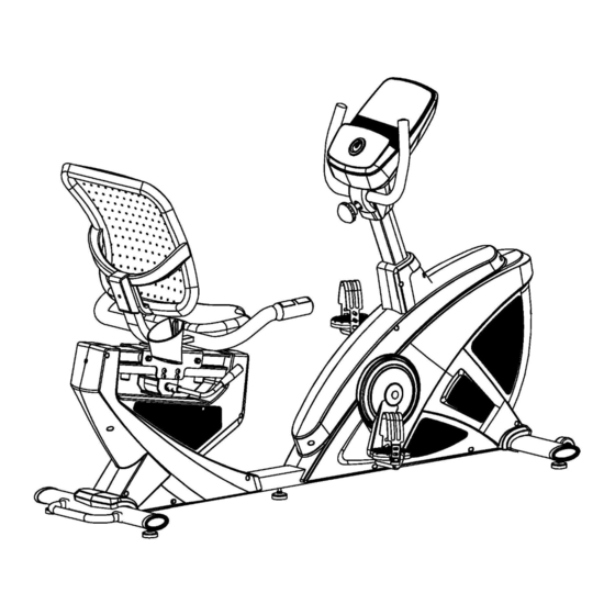
- Page 1 Recumbent Bike User’s Manual *The specifications of this product may vary slightly from the illustrations and are subject to change without notice.
- Page 2 - 1 -...
-
Page 3: Before You Start
Before You Start Thank you for purchasing this Recumbent Bike! For your safety and benefit, read this manual carefully before using the machine. Prior to assembly, remove components from the box and verify that all the listed parts were supplied. Assembly instructions are described in the following steps and illustrations. - Page 4 EXPLOADED DIAGRAM - 3 -...
-
Page 5: Parts List
PARTS LIST Part Part Description Description Main frame Adaptor Front stabilizer Backrest Rear stabilizer Square end cap Handlebar post Phillips screw Fixed handlebar Plastic handle knob Nylon nut M10 Allen bolt M8×12 Flat washer D10×2 Flat washer Roller Seat Allen bolt M10×50 Extension pulse wire 1 Oval end cap Extension pulse wire 2... -
Page 6: Specification
Specification Disc weight: 7 kg Console: with Bluetooth / MP3 /USB Pedal: With bearings Seat: Adjustable Maximum user weight: 120 Kg Display: with phone jack / iPad Weight: 48,5 kg Dimensions: 163,5 x 67 x 105,5 cm THE WARRANTY IS NOT VALID IF: The machine is placed outdoors or exposed to sun and dust. CAUTION! The company does not have no responsibility for causing damage due to misuse of the roduct and non-compliance with the instructions for use. - Page 7 ASSEMBLY INSTRUCTIONS Note: Assembly requires 2 people. PREPARATION: Before assembling, make sure that you will have enough space around the item; Use the present tooling for assembling; before assembling, please check whether all needed parts are available. It is strongly recommended this machine to be assembled by two or more people to avoid possible injury.
- Page 8 STEP 2: Connect the Sensor Wire (21) and Extension Pulse Wires 1(36) to the Extension Wire (22) and Extension Pulse Wires 2 (37), then lock the Handlebar Post (4) on the Main Frame (1) with the Allen Bolts (19), Spring Washers (14) and Flat Washers (7) as shown. Attach the Mast cover (23L/R) to the Main Frame (1) with the Phillips Tapping Screws (24).
- Page 9 STEP 4: A: Connect the Extension Pulse Wires 2 (37), Extension Wire (22) with the Wires from the Console (38), then lock the Console (38) on the computer bracket of the Handlebar Post (4) with the Phillips Screws (31). B: Fit and lock the Handlebar Cover (25a/b) to the Handlebar Post (4) with the Phillips Tapping Screws (24).
- Page 10 STEP 6: A: Connect the Pulse Wires (45) with Extension Pulse Wires 3 (44) of the Main Frame (1), then lock the Seat Frame (50) on the Adjustable Bracket (46) with the Allen Bolts (33) and Flat Washers (43) as shwon.
-
Page 11: Console Instruction
Console Instruction SM2526-67 KEY FUNCTION -Start or Stop workout. START/STOP -In STOP mode, press this key to go back to main menu; -Hold on pressing for 2 seconds, computer will reboot and start RESET from user setting. -Increase resistance level. UP(+)... -
Page 12: Operation Procedure
OPERATION PROCEDURE 1. Plug in power supply (or press RESET KEY for 2S), BUZZER will sound one beep for 1 second. And LCD full display 2 seconds (Drawing 1) then display wheel diameter and KM or ML (Drawing 2). Then console come to Standby mode (Drawing 3). Drawing 1 Drawing 2 Drawing 3... - Page 13 5. If user want to select ADVANCE mode (Drawing11), press START/STOP no matter in any mode, then press RESET go to main menu. When MANUAL is flashing, press UP(+)twice and MODE key to enter ADVANCE mode (Drawing12). Press UP (+) /DOWN (-) to select ADVANCE 1~4 and confirm by MODE.
- Page 14 9. RECOVERY mode After exercising for a period of time, keep holding on hand grips and press “RECOVERY” Button. All function display will stop except “TIME” starts counting down from 00:60 to 00:00 (Drawing 22). Screen will display your heart rate recovery status with the F1, F2….to F6 (Drawing 23).
- Page 15 System reminder: ①effective operation- one short beep; χ ※This console has the bell prompt function on button: ②ineffective operation- two short beeps; ③any function value count down to 0 during workout- 2 short beeps every second ④In CARDIO & WATT CONTROL mode when console is forced to stop- continuous 6 ⑤When PULSE exceed setting value- 2 short beeps every second short beeps.
- Page 16 Connections instructions through Bluetooth with Smartphone & tablet. Below are URLs to iConsole+Training at App sotre and Google Play https://itunes.apple.com/tw/app/ic-training/id1347028353 https://play.google.com/store/apps/details?id=com.changyow.icp4th To learn more about iConsole+Training app, please visie below URL. There are detailed description of iContole+ Training app, and we will keep developing more functions and ensure iConsole+Training stability as well as enrich the description on website.
-
Page 17: Warm-Up And Cool-Down
WARM-UP and COOL-DOWN A successful exercise program consists of a warm-up, aerobic exercise, and a cool-down. Do the entire program at least two and preferably three times a week, resting for a day between workouts. After several months, you can increase your workouts to four or five times per week. WARM-UP The purpose of warming up is to prepare your body for exercise and to minimize injuries. - Page 18 • Warranty period is 2 years for mechanical, electrical / electronic parts and 5 years for the metal frame. • X-TREME STORES S.A. undertakes to repair the machine free of charge in the event of damage due solely to a manufacturing fault. The warranty covers the cost of the spare parts. Replacement of spare parts or not is up to the company technicians.
- Page 19 - 18 -...
- Page 20 Koupi Avenue 34, Koropi P.C. 19441 P.O.Box 6201 Tel.: 210 66 20 921 -2 - FAX: 210 66 20 923 E-mail: info@xtr.gr • f/xtrstores • /@xtr.gr Tel for all Greece: 801.11.15.100 www.xtr.gr - 19 -...