
Summary of Contents for OptiSense PaintChecker industrial
- Page 1 Version 3.1 Operation manual PaintChecker industrial PaintChecker industrial n-gauge...
-
Page 2: Table Of Contents
8. Communication Protocols ................................. 23 8.1 Introduction ....................................23 8.2 Modbus RTU ....................................23 8.3 Profinet ......................................23 8.4 OptiSense ASCII protokoll............................... 23 8.5 Error codes ....................................24 9. Maintenance ......................................25 9.1 Spare parts ....................................25 9.2 Replacing the sensor cable ..............................25... - Page 3 10.1 System specifications................................27 10.2 Measurement system control protocol ........................... 32 Table of Figures Fig. 1: PaintChecker industrial n-gauge with various laser and LED sensors Fig. 2: Operating principle of photothermal coating thickness measurement Fig. 3: Tube LLP3.5, LHP3.5, LHP10 Fig.
-
Page 4: Introduction
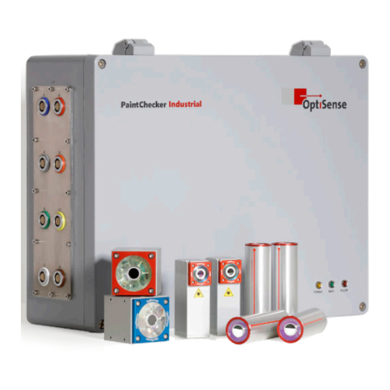
PLC controller via various interfaces. understanding only and may differ from the actual design. Fig. 1: PaintChecker industrial n-gauge with various laser and LED sensors 1.4 Copyright The OS Manager software provided with the system This operation manual is protected by copyright. -
Page 5: Customer Service
Violations will result in liability for damages. The manufacturer reserves the right to assert further rights. The manufacturer retains the copyright. © OptiSense GmbH & Co. KG | Annabergstraße 120 | 45721 Haltern am See | GERMANY© 1.5 Customer service... -
Page 6: Safety Instructions
2.1 Symbol explanation of pictograms and 2.2 Proper use signal words The PaintChecker industrial photothermal measuring Safety instructions are indicated by hazard picto- system is used to determine the thickness of wet and grams in this operation manual. These pictograms dry organic coatings for quality assurance and pro- convey information about the type of danger. -
Page 7: Risks Caused By Electricity
Position: Near the light source (lens of the sensor) • Work on the electronics of the measuring system Warning sign 4 may only be carried out by OptiSense or by Laser class 1M personnel trained by OptiSense. Position: over status LEDs of •... -
Page 8: Fire Hazards
• If the sensor is damaged, the system must no longer be used. The sensor must be returned LARES immediately to OptiSense GmbH & Co. KG A health hazard due to invisible light radi- ation of class 1 can be excluded when used 2.6 Fire hazards... -
Page 9: Responsibility Of The Operator
The operator remains responsible for ensuring that the measuring system is free from technical faults at all times. The operator must have all safety devices checked regularly for functionality and completeness. PaintChecker Industrial | 9... -
Page 10: Product Description
– even during prolonged irradiation. 3.3 Features and area of application The PaintChecker industrial is a photothermal coating thickness measurement system for automated oper- ation in production. It builds on OptiSense's many years of experience in the manufacture of reliable... -
Page 11: Model Overview Sensors
The geometry of the sensor as well as the measuring distance and spot size vary according With the PaintChecker industrial systems, a wide vari- to the respective measuring requirements. ety of coatings can be measured non-destructively in wet or dry condition, regardless of the geometry. -
Page 12: Fig. 4: Dimensional Drawing Industrial Angle Sensors Llp1.6, Lhp1.66
Angle und Tube the cube-shaped housing can be mounted particu- larly flexibly due to the freely selectable orientation The OptiSense laser sensors Angle and of the cable connection while their large contact sur- Tube use a diode laser as the light source face ensures optimum heat dissipation. -
Page 13: Controller Model Overview
The controller in a robust, have a reinforced power supply, which is housed in a dust-protected aluminium housing is separate enclosure for the PaintChecker industrial n- available in different versions for laser and LED gauge HP. In addition to the higher excitation power, sensors. -
Page 14: Connections Of The Controller
Service interface for Anybus USB B 2.0 Service interface for maintenance calibration based on the internal OptiSense protocol (to be used by OS Manager) Safety circuit connection for laser enable (2x2 line channels) and reset control (2 lines) Power indicator (yellow) Power supply 110 - 230 V switched on Fig. -
Page 15: Accessories
Output signals. For the Profinet IO connection a Gdsml file as well as a TIA V14/V15 module is available from OptiSense.. 3.8 Accessories The optional accessories of the measuring system are listed in the Data Sheet Controller industrial and Data Sheet Sensors industrial. -
Page 16: Installation
Fig. 10: Connector assignment 16 | PaintChecker Industrial... -
Page 17: Mounting The Sensor
The sensor is to be mounted at a suitable location in the production line or on a motion unit. It must be ensured that the sensor reliably maintains the specific measuring distance to the part to measure. PaintChecker Industrial | 17... -
Page 18: Commissioning
Fig. 13: Correct distance to the measured part • The PaintChecker industrial Controller may only be operated with the housing closed! 5.4 Establishing Communication • The PaintChecker industrial system can only be 5.4.1 Prerequisites operated with the safety circuit closed. • The general instructions for commissioning have •... -
Page 19: Calibration
For all users who require a particularly high level of Calibrations that are specifically relevant to the par- safety, accuracy and reliability from their coating ticular customer are stored by OptiSense on each in- thickness measurement, the reference masters from strument in the form of system calibrations. The... -
Page 20: Fig. 15: Reference Master
Our reference masters are certified by a DAkkS labor- atory and are regarded as a high standard in terms of accuracy and traceability 9,60 8,50 4,50 Fig. 17: Typical application of a Reference Master Fig. 15: Dimensional drawing of a reference sample 20 | PaintChecker Industrial... -
Page 21: Operation
1. With PaintChecker industrial, the sensors to be ment series. This bit is only used for special applica- used must be activated via control channels 1.0 - tions in consultation with OptiSense. - Page 22 A reference glass (NG1) with well defined optical and thermal properties which can be used as a test speci- men is available from OptiSense as an accessory. During the test, this glass should be positioned ex- actly at the working distance (see Technical Data).
-
Page 23: Communication Protocols
8.1 Introduction 8.4 OptiSense ASCII protokoll Depending on the equipment, various communica- The PaintChecker industrial controller is controlled by tion interfaces are available for controlling the ASCII commands via the serial interface of the meas- PaintChecker industrial system. The most common uring system. -
Page 24: Error Codes
• check the correct positioning of the reference sample to the sensor • if the error persists, please contact OptiSense Service. Time signal of reference measurement out- • Make sure the reference surface is clean and free... -
Page 25: Maintenance
• Harting connector set (power supply, network and safety circuit) Spare parts fitting to the particular measuring system can be obtained from OptiSense by quoting the serial number of the controller and the equipment. E-mail: info@optisense.com Tel. +49 23 64 50 882-0 9.2 Replacing the sensor cable... -
Page 26: Replacing A Sensor
All maintenance work must be carried out exclusively Config software is started. by OptiSense GmbH & Co. KG. In particular, the con- troller unit must never be opened by unqualified per- The Update button in the upper left corner is used to... -
Page 27: Technical Data
Dimensions (L x W x H) 87 x 28 x 41 mm Ø 30 x 102 mm 50 x 51.6 x 55 mm Weight 180 g 150 g 280 g IP Code IP 50 Table 4: Sensor specifications PaintChecker Industrial | 27... -
Page 28: Table 5: Controller Specifications
Communication with a connected PC is performed via serial interface and/or Profinet IO. The complete control of the measurement process and storage of the measurement data is available on a PC by using visualisation software provided by OptiSense. Technical Data | Controller industrial Model n-gauge... -
Page 29: Fig. 22: Circuit Diagram
10.1.3 Circuit Diagram Fig. 21: Circuit diagram PaintChecker Industrial | 29... -
Page 30: Table 6: Pin Assignment X14
RS232 Rx X17.2 1* Calculation of the max. cable length I in the input circuit: I /km) Table 9: Pin assignment X17 lmax with R = total cable resistance and R /km = cable resistance/km lmax 30 | PaintChecker Industrial... -
Page 31: Fig. 23: Connector Locations
Fig. 22: Connector locations PaintChecker Industrial | 31... -
Page 32: Measurement System Control Protocol
1 Bit oce,4,<#> con4 Activate sensor 5 1 Bit oce,5,<#> con5 Activate sensor 6 1 Bit oce,6,<#> con6 Activate sensor 7 1 Bit oce,7,<#> con7 Activate sensor 8 1 Bit oce,8,<#> con8 Table 10: Input signals 32 | PaintChecker Industrial... - Page 33 Not used 2 Byte 176 - 191 Not used 2 Byte 192 - 207 Not used 2 Byte 208 - 223 Not used 2 Byte 224 - 239 Not used 2 Byte 240 - 255 PaintChecker Industrial | 33...
- Page 34 Temperature of target object 2 Byte bgt5 624 - 639 at sensor 5 Temperature of target object 2 Byte bgt6 640 - 655 at sensor 6 Temperature of target object 2 Byte bgt7 656 - 671 at sensor 7 34 | PaintChecker Industrial...
-
Page 35: Table 11: Output Signals
Error code of sensor 6 2 Byte err6 976 - 991 Error code of sensor 7 2 Byte err7 992 - 1007 Error code of sensor 8 2 Byte err8 1008 - 1023 Table 11: Output signals PaintChecker Industrial | 35... - Page 36 OptiSense. At your service, worldwide. Headquarter Germany America Asia OptiSense GmbH & Co. KG USA | UPA Technology Inc. China | China Physical and Chemistry Annabergstraße 120 Brazil | groupwork Serviços de Analysis Technology Development Co., 45721 Haltern am See Representação Comercial Ltda.
Need help?
Do you have a question about the PaintChecker industrial and is the answer not in the manual?
Questions and answers