
Summary of Contents for Potter NCE-1000
- Page 1 Potter NCE-1000 and NCF-1000 Peer to Peer Panel Network Guide Potter Electric Signal Company, LLC St. Louis, MO Customer Service: (866) 240-1870 • Technical Support: (866) 956-1211 • Fax: (314) 595-6999 www.pottersignal.com Guide #8830161–Rev B 3/23...
- Page 2 WARRANTY INFORMATION The essential purpose of any sale or contract for sale of any of the products listed in the POTTER catalog or price list is the furnishing of that product. It is expressly understood that in furnishing said product, POTTER does not agree to insure the Purchaser against any losses the Purchaser may incur, even if resulting from the malfunction of said product.
-
Page 3: Table Of Contents
PEER TO PEER NETWORKING • 8830161 • REV B • 3/23 Table of Contents Section 1: Introduction ..........................1 Section 2: Network Card Setup ........................2 Section 3: Recommended Steps for Setting Up the Network ..............6 Section 4: Network Programming Overview...................7 Section 5: Wiring Diagrams ........................17... - Page 4 PEER TO PEER NETWORKING • 8830161 • REV B • 3/23 THIS PAGE INTENTIONALLY LEFT BLANK...
-
Page 5: Section 1: Introduction
Purpose Of This Guide This guide is intended to assist in the installation and programming of the NCE-1000 and NCF-1000 network cards. It is recommended that the user follows the procedures as outlined in this guide to assist in proper installation and prevent damage to the control panel and associated equipment. -
Page 6: Section 2: Network Card Setup
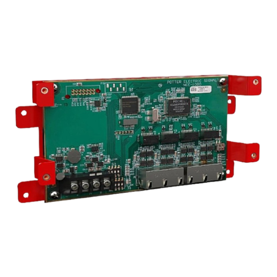
System Defaults: DIP Switches The NCE-1000 has three (3) sets of dip switches while the NCF-1000 has two (2) sets of dip switches, that must be set prior to installation. Both modules include dip switches S1 and S3. Only the NCE-1000 (shown below) includes the 2 position S2 dip switch, used to set ground fault detection. - Page 7 PEER TO PEER NETWORKING • 8830161 • REV B • 3/23 Setting DIP Switch S1 – NCE-1000 & NCF-1000 Network Cards Dip switch S1 is a 5-position dip switch used to set the P-Link address of the network card. For most applications, this switch will be set to address 1 as only one (1) network card will be installed per panel.
- Page 8 PEER TO PEER NETWORKING • 8830161 • REV B • 3/23 Setting DIP Switch S3 – NCE-1000 & NCF-1000 Network Cards Dip switch S3 is a 4-position dip switch and is set according to the physical location in the network and Class A/B configurations.
- Page 9 PEER TO PEER NETWORKING • 8830161 • REV B • 3/23 Setting DIP Switch S2 – NCE-1000 Network Card Dip switch S2 is a 2-position dip switch and must be set to the ON position to enable ground fault detection for ports 3 & 4 on the NCE card.
-
Page 10: Section 3: Recommended Steps For Setting Up The Network
1 - Learn, then option 1 - Learn All. 5. Using the Potter Fire Panel Programming Software click File and select New Network. Directly connect the computer’s ethernet cable to Port 2 on a network card, then click Upload and Add Panel in the software. -
Page 11: Section 4: Network Programming Overview
PEER TO PEER NETWORKING • 8830161 • REV B • 3/23 Section 4: Network Programming Overview To set up a Network using Potter’s Fire Panel Programmer, click on File and select New Network from the drop-down list. Figure 6. New Network In this screen, panels are added to the network and assigned to a “Building”. - Page 12 PEER TO PEER NETWORKING • 8830161 • REV B • 3/23 Figure 8. Upload and Add Panel Figure 9. Import Panel File...
- Page 13 PEER TO PEER NETWORKING • 8830161 • REV B • 3/23 Assigning Panels to a Building When panels are added to the network configuration, they are automatically assigned to Building 1. In a campus application each panel will typically be assigned to a different Building. Additional Buildings are added by clicking on the Add Building button.
- Page 14 PEER TO PEER NETWORKING • 8830161 • REV B • 3/23 Remote Access Code & Users The Remote Access Code and Users tab shown on the left of the screen serve the same purpose as with non-networked panels but in a networked system those settings are common for every panel on the network. Remote Access Code tab is where the Remote Access User Name and Remote Access Password are entered for a networked system.
- Page 15 PEER TO PEER NETWORKING • 8830161 • REV B • 3/23 Input/Output Correlations – Reference Points Reference Points are available in the Zones tab of all panels. Reference Points includes a list of software zones for every panel on the network. This allows a zone of one panel to be assigned to the zone of another panel on the network. Reference Points are assigned to zones using the same drag and drop method used for points.
- Page 16 PEER TO PEER NETWORKING • 8830161 • REV B • 3/23 This example will demonstrate how to network page from Building A to Building B using reference points and “Network Page” style zones. In the figure below shows Building A and Building B on the same network. First, a designated push button needs to be setup in the Building A panel to initiate network paging to Building B then assign corresponding speaker outputs from Building B to become active when push button in Building A is selected using reference points.
- Page 17 PEER TO PEER NETWORKING • 8830161 • REV B • 3/23 Network Annunciator An RA-6500 remote annunciator or 4x40 character panel display can be configured as a network annunciator. A network annunciator can be assigned to display events and utilize control functions. To set an LCD Annunciator as a Network Annunciator click on the drop-down next to the annunciator and select Network Annunciator, as shown below for the Admin building.
- Page 18 PEER TO PEER NETWORKING • 8830161 • REV B • 3/23 Network Communicator A single panel on the network can report to a central station for all panels on the network. The process for programming the IP communicator or UD-2000 DACT is the same as with non-networked panels. The difference is a Panel Selection option is available to select the panels that should report through the communicator.
- Page 19 The NCE and NCF network cards are added to a panel configuration using the same method as other P-Link cards. While viewing individual panels in a network configuration the NCE-1000 and NCF-1000 will be available. These options are not available until the panel configuration is added to a network. Clicking on Add Device adds the card to the panel’s configuration.
- Page 20 PEER TO PEER NETWORKING • 8830161 • REV B • 3/23 Downloading a network configuration The network configuration is downloaded to panels on the network via an ethernet cable connected from the computer into Port 2 on either an NCE or NCF Card. The configuration will be downloaded to all panels on the network that require a program change.
-
Page 21: Section 5: Wiring Diagrams
PEER TO PEER NETWORKING • 8830161 • REV B • 3/23 Section 5: Wiring Diagrams Wiring Diagram – NCE-1000 Network Card Ethernet - Class B FACP PANEL 1 P-COMM NCE-1000 P-Link Dip switch bank S2 sets ground fault DIP SW S3 S1 = OFF detection for Port 3 &... - Page 22 PEER TO PEER NETWORKING • 8830161 • REV B • 3/23 Wiring Diagram – NCF-1000 Network Card Fiber - Class B FACP PANEL 1 P-COMM NCF-1000 P-Link DIP SW S3 S1 = OFF S2 = OFF S3 = OFF S4 = OFF Fiber Fiber Port 1...
- Page 23 PEER TO PEER NETWORKING • 8830161 • REV B • 3/23 Wiring Diagram – NCE-1000 Network Card Ethernet - Class A (With Return) FACP PANEL 1 P-COMM NCE-1000 P-Link Dip switch bank S2 sets ground fault DIP SW S3 S1 = OFF detection for Port 3 &...
- Page 24 PEER TO PEER NETWORKING • 8830161 • REV B • 3/23 Wiring Diagram – NCF-1000 Network Card Fiber - Class A FACP PANEL 1 P-COMM NCF-1000 P-Link DIP SW S3 S1 = OFF S2 = OFF S3 = ON S4 = OFF Fiber Fiber Port 1...
- Page 25 PEER TO PEER NETWORKING • 8830161 • REV B • 3/23 Wiring Diagram – NCE-1000 & NCF-1000 Network Cards (Copper to Fiber) - Class B FACP PANEL 1 P-COMM NCF-1000 P-Link DIP SW S3 S1 = OFF S2 = OFF...
- Page 26 PEER TO PEER NETWORKING • 8830161 • REV B • 3/23 Wiring Diagram – NCE-1000 & NCF-1000 Network Cards (Copper to Fiber) - Class A FACP PANEL 1 P-COMM NCF-1000 P-Link DIP SW S3 S1 = OFF S2 = OFF...
- Page 27 PEER TO PEER NETWORKING • 8830161 • REV B • 3/23 Wiring Diagram – NCE-1000 & NCF-1000 Network Cards Star Configuration – Class B (ONLY) FACP PANEL 1 FACP PANEL 4 P-COMM P-COMM NCF-1000 NCF-1000 P-Link P-Link DIP SW S3...
- Page 28 PEER TO PEER NETWORKING • 8830161 • REV B • 3/23 Wiring Diagram – NCE-1000 Network Card Ethernet - Extender – Class B FACP PANEL 1 P-COMM NCE-1000 P-Link Dip switch bank S2 sets ground fault DIP SW S3 S1 = OFF detection for Port 3 &...
- Page 29 PEER TO PEER NETWORKING • 8830161 • REV B • 3/23 Wiring Diagram – NCE-1000 Network Card Ethernet - Extender – Class A FACP PANEL 1 P-COMM NCE-1000 P-Link DIP SW S3 Dip switch bank S2 sets ground fault S1 = ON detection for Port 3 &...
- Page 30 PEER TO PEER NETWORKING • 8830161 • REV B • 3/23 Wiring Diagram – NCE-1000 Network Card Ethernet - Class A segments between panels FACP PANEL 1 P-COMM NCE-1000 Dip switch bank S2 sets ground fault P-Link DIP SW S3 detection for Port 3 &...
- Page 31 PEER TO PEER NETWORKING • 8830161 • REV B • 3/23 Wiring Diagram - Integrated Voice System Connecting to NCE-1000 Wiring Diagram - Integrated Voice System Connecting to NCF-1000...
Need help?
Do you have a question about the NCE-1000 and is the answer not in the manual?
Questions and answers