
Summary of Contents for Load Cell Systems WDESK-G
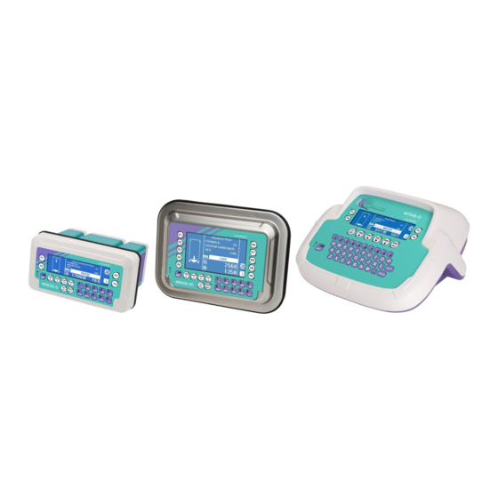
- Page 1 ENGLISH ENGLISH ENGLISH ENGLISH Installation and User Manual version 1.01 WDESK-G WINOX-G/2G WTAB-G/2G Base...
- Page 2 SYMBOLS Here are the symbols used in the manual to draw the reader's attention: Caution! Risk of electric shock. Caution! This operation must be performed by skilled personnel. Pay particular attention to the following instructions. Further information. WARRANTY 24 months from the date of the delivery note. Warranty covers only failures of defective components (due to construction defects or defects in materials) and includes replacement or repair of the components and related labor costs.
-
Page 3: Table Of Contents
TABLE OF CONTENTS USER WARNINGS ........................1 RECOMMENDATIONS FOR CORRECT INSTALLATION OF WEIGHING INSTRUMENTS . 1 RECOMMENDATIONS FOR CORRECT INSTALLATION OF THE LOAD CELLS ....2 LOAD CELL INPUT TEST (QUICK ACCESS) ................4 LOAD CELL TESTING ........................4 MAIN SPECIFICATIONS OF THE INSTRUMENT ..............5 BUFFER BATTERY .......................... - Page 4 SEMI-AUTOMATIC ZERO (WEIGHT ZERO-SETTING FOR SMALL VARIATIONS) ....30 PEAK .............................. 31 ANALOG OUTPUT(ONLY FOR INSTRUMENTS WHERE THIS OPTION IS AVAILABLE) ..32 SERIAL COMMUNICATION SETTING ..................34 RS232 SERIAL COMMUNICATION ....................36 RS485 SERIAL COMMUNICATION ....................36 DIRECT CONNECTION BETWEEN RS485 AND RS232 WITHOUT CONVERTER ...... 36 PROGRESSIVE WEIGHED VALUES ....................
- Page 5 DECLARATION OF CONFORMITY - EU ................60 DECLARATION OF CONFORMITY - UKCA ................. 61...
-
Page 6: User Warnings
USER WARNINGS RECOMMENDATIONS FOR THE PROPER USE OF WEIGHING INSTRUMENT Keep away from heat sources and direct sunlight Repair the instrument from rain (except special IP versions) Do not wash with water jets (except special IP versions) Do not dip in water Do not spill liquid on the instrument Do not use solvents to clean the instrument Do not install in areas subject to explosion hazard (except special Atex versions) -
Page 7: Recommendations For Correct Installation Of The Load Cells
RECOMMENDATIONS FOR CORRECT INSTALLATION OF THE LOAD CELLS SIZING OF LOAD CELLS CAPACITY For safety reasons, in case of static weighing, it is advisable to use the load cells at a maximum of 70- 80% of its nominal capacity (assuming that the load is uniformly distributed over the entire weighed structure);... - Page 8 EARTHING THE WEIGHED STRUCTURE By means of a copper wire with suitable cross-section, connect the cell upper support plate with the lower support plate, then connect all the lower plates to a single earthing system. Electrostatic charges accumulated because of the product rubbing against the pipes and the weighed container walls are discharged to the ground without going through or damaging the load cells.
-
Page 9: Load Cell Input Test (Quick Access)
LOAD CELL INPUT TEST (QUICK ACCESS) From the weight display, press for 3 seconds; the response signal of the load cells is displayed, expressed in mV with four decimals. LOAD CELL TESTING Load cell resistance measurement (use a digital multimeter): - Disconnect the load cells from the instrument and check that there is no moisture in the cell junction box caused by condensation or water infiltration. -
Page 10: Main Specifications Of The Instrument
Instruments with P, D type connectors: included switching power supply plug 24 V 450 mA, input 100÷240 VAC, 3 meters long cable. Display: Model Display Resolution Viewing area WDESK-G STN transmissive graphic LCD, white on WINOX-G 240x64 pixel 133x39 mm blue, backlit WTAB-G... - Page 11 X - Atex cable gland 122x226x164 mm IP67 Atex II3GD version 96x186 mm (connectors included) (areas 2 -22) IP67 protection rating Wall installation with bracket 122x230x250 mm ca. (can also be installed on table) (bracket included) WINOX Type of connectors Max.
-
Page 12: Buffer Battery
WTAB Type of connectors Max. encumbrance Drilling D – D-Sub connector IP40 protection rating 315X315X180 mm Power supply included BUFFER BATTERY The instrument is equipped with an internal battery that allows to keep active the internal clock even in the event of power failure. At the first start and after long periods of inactivity, leave the instrument on for at least 12 hours to fully charge the battery. -
Page 13: After A Blackout
AFTER A BLACKOUT After a blackout the instrument DOES NOT come on again automatically, you have to press ON. To guarantee an automatic restart after a blackout, disable the ON key as follows: - disconnect power supply and open the instrument; - identify flat connectors coming from the keypad on the main board;... -
Page 14: Technical Specifications
TECHNICAL SPECIFICATIONS POWER SUPPLY and CONSUMPTION (VDC) 12/24 VDC ±10%; 6 W (standard) 115/230 VAC; 50-60 Hz; 6 VA POWER SUPPLY and CONSUMPTION (VAC) (optional only for WDESK – WINOX-P) NO. OF LOAD CELLS IN PARALLEL and SUPPLY max 8 (350 ohm); 5 VDC / 120 mA LINEARITY / ANALOG OUTPUT LINEARITY <... -
Page 15: Electrical Connections
ELECTRICAL CONNECTIONS BASIC INFORMATION - It is recommended that the power supply negative pole be grounded (WDESK-D, WINOX, WTAB: connect the earthing system to the dedicated external terminal ). - It is possible to supply up to eight 350 ohm load cells or sixteen 700 ohm load cells. - For 4-wire load cells, make a jumper between EX- and REF- and between EX+ and REF+. -
Page 16: Changing Voltage 115 Vac / 230 Vac (Wdesk)
CHANGING VOLTAGE 115 VAC / 230 VAC (WDESK) Access instrument board by removing the six bottom screws and work on the welding side: join the red points using a stiff wire. 230 Vac 115 Vac KEY TO P, Q, X TYPE CONNECTORS Terminal Signal Terminal Signal OUTPUT No. -
Page 17: Key To D Type Connectors
OUTPUT No. 2 PHASE (115/230 VAC optional ver.) OUTPUT No. 3 NEUTRAL (115/230 VAC optional ver.) GROUND (115/230 VAC optional ver.) *) Use only as power supply for instrument inputs. To access the terminal strip on the WDESK instruments with cable glands, you need to remove the bottom of the instrument unscrewing the six screws. - Page 18 RS232: RXD yellow RS232: TXD blue Male RS232: SHIELD, GND black RS232 serial port +OUTPUT (24 VDC)* -OUTPUT (24 VDC)* black Male RS485: + yellow RS485: SHIELD, GND black RS485 serial port RS485: - blue with 24 VDC RS485: - blue output RS485: +...
-
Page 19: Keys And Symbols Functions
KEYS AND SYMBOLS FUNCTIONS KEYS Short press Long press (3 s) Into menus Power-on Power-off Cancel or return to previous Semi-automatic zero Tare resetting menu Gross Net Net Gross Select figure to be modified Select figure to be modified Modify figure or go to next Show date and time on display menu item... -
Page 20: Menu Map
MENU MAP Into menus changes are applied right after pressing the ENTER key ( no further confirmation is required). SETPOINT … … … SYSTEM PARAMETERS ... -
Page 21: Lcd Graphic Display
6) Instrument serial number These information are required to request technical assistance. As the start-up sequence is completed, if no error occurs, the instrument shows the main screen: WDESK-G, WINOX-G, WTAB-G 1) Unit of measure 2) Gross weight symbol 3) Inputs and outputs status... -
Page 22: Setpoint Visualization
SETPOINT VISUALIZATION From gross weight displaying, hold down the function key to show the setpoint screen: 1) Unit of measure 2) Gross weight symbol 3) Setpoint status and value 4) Gross weight value 5) Number of setpoint class* *) Only for instruments equipped with E/EC option. Setpoint status and value: if weight exceeds setpoint value the symbol is displayed, otherwise symbol is displayed. -
Page 23: Language Setting
LANGUAGE SETTING The instrument supports several languages to show LCD display messages. > LANGUAGE (default) - ITALIANO - ENGLISH - FRANÇAIS - ESPAÑOL - JOLLY “JOLLY” language: allows to customize the text of messages; it can also be loaded onto the instrument (via PC) specific character sets to write messages in other languages. -
Page 24: Customizing Messages Of Lcd Graphic Display
CUSTOMIZING MESSAGES OF LCD GRAPHIC DISPLAY The instrument allows to edit messages in the following way: > PLANT NAME > LOT > MSG JOLLY* > EDIT MSG (only after having selected the JOLLY language) *) allows to edit all display messages Select the message to edit, the following screen appears: 1) Message box 2) Selected character... -
Page 25: Instrument Commissioning
INSTRUMENT COMMISSIONING To turn on the instrument press ON. To turn it off press OFF for about 3 seconds: when appears release the key. After a blackout the instrument DOES NOT come on again automatically, you have to press ON. To guarantee an automatic restart after a blackout, disable the ON key (see section AFTER A BLACKOUT). -
Page 26: Programming Of System Parameters
PROGRAMMING OF SYSTEM PARAMETERS From the weight display, press simultaneously keys MENU and ESC to access the parameter setting. MENU/ENTER: to enter a menu/confirm the data entry. to modify the displayed value or menu item. to select a new figure. ESC: to cancel and return to the previous menu. -
Page 27: Maximum Capacity
MAXIMUM CAPACITY : maximum displayable weight (from 0 to full scale; default: 0). When the weight exceeds this value by 9 divisions, the display shows . To disable this function, set 0. TARE WEIGHT ZERO SETTING This menu may also be accessed directly from the weight display, holding down the key for 3 seconds. -
Page 28: Real Calibration (With Sample Weights)
REAL CALIBRATION (WITH SAMPLE WEIGHTS) After having performed the THEORETICAL CALIBRATION and TARE WEIGHT ZERO SETTING, this function allows correct calibration to be done using sample weights of known value and, if necessary, any deviations of the indicated value from the correct value to be corrected. Load onto the weighing system a sample weight, which must be at least 50% of the maximum quantity to be weighed. -
Page 29: Filter On The Weight
FILTER ON THE WEIGHT Setting this parameter allows a stable weight display to be obtained. To increase the effect (weight more stable) increase the value (from 0 to 9, default 4). As seen in the diagram: - By confirming the message, the currently programmed filter value is displayed. - By changing and confirming the value, the weight is displayed and it will be possible to experimentally verify its stability. -
Page 30: Zero Parameters
ZERO PARAMETERS RESETTABLE WEIGHT SETTING FOR SMALL WEIGHT CHANGES (from 0 to full scale; default: 300; considered decimals: 300 – 30.0 – 3.00 – 0.300): this parameter indicates the maximum weight value resettable by external contact, keypad or serial protocol. AUTOMATIC ZERO SETTING AT POWER-ON ... -
Page 31: Setting Units Of Measure
SETTING UNITS OF MEASURE These are the available units of measure: kilograms : grams : : tons pounds* : : newtons* litres* : bars* : : atmospheres* pieces* : newton metres* : : kilogram metres* other generic units of measure not included in the list* : If the print function is enabled, the symbol corresponding to the selected unit of measure will be printed after the measured value. - Page 32 : litres, in set the specific weight in kg/l, assuming that the system is calibrated in kg; : bar, the value set in will be multiplied by the weight value currently displayed; : atmosphere, the value set in will be multiplied by the weight value currently displayed; : pieces, in ...
-
Page 33: Outputs And Inputs Configuration
OUTPUTS AND INPUTS CONFIGURATION OUTPUTS The outputs are set by default as follows: / / / / . Possible operation modes: - (normally open): the relay is de-energised and the contact is open when the weight is lower than the programmed setpoint value;... -
Page 34: Semi-Automatic Tare (Net/Gross)
INPUTS Default: input 1 = input 2 = input 3 = Possible operation modes: - (NET/GROSS): by closing this input for no more than one second, it’s making an operation of SEMI-AUTOMATIC TARE and the display will show the net weight. To display the gross weight again, hold the NET/GROSS input closed for 3 seconds. -
Page 35: Preset Tare (Subtractive Tare Device)
PRESET TARE (SUBTRACTIVE TARE DEVICE) It is possible to manually set a preset tare value to be subtracted from the display value provided that the ≤ max capacity condition is verified. By default the instrument shows the last programmed preset tare value: to apply it press and then ENTER. -
Page 36: Peak
PEAK Keep closed PEAK input, the following screen appears: WDESK-G, WINOX-G, WTAB-G 1) Unit of measure 2) Weight value WINOX-2G, WTAB-2G 3) Inputs and outputs status 4) Peak value 5) Weight type 6) LCD display configuration menu 7) Setpoint display By opening the input the current weight is displayed. -
Page 37: Analog Output(Only For Instruments Where This Option Is Available)
ANALOG OUTPUT(ONLY FOR INSTRUMENTS WHERE THIS OPTION IS AVAILABLE) - : it selects the analog output type (4÷20 mA, 0÷20 mA, 0÷10 V, 0÷5 V, ±10 V, ±5 V; default: 4÷20 mA). For the output ±10 V and ±5 V the soldered jumper SW1 must be closed: ▫... - Page 38 Minimum and maximum values which can be set for zero and full scale corrections: ANALOG OUTPUT TYPE Minimum Maximum 0÷10 V -0.150 10.200 0÷5 V -0.150 5.500 ±10 V -10.300 10.200 ±5 V -5.500 5.500 0÷20 mA -0.200 22.000 4÷20 mA -0.200 22.000 NOTE: the analog output may also be used in the opposite manner, i.e.
-
Page 39: Serial Communication Setting
SERIAL COMMUNICATION SETTING - / : communication port. - : it disables any type of communication (default). - : MODBUS-RTU protocol; possible addresses: from 1 to 99 (see Communication protocols manual). - : ASCII bidirectional protocol; possible addresses: from 1 to 99 (see Communication protocols manual). - Page 40 - : - : no parity (default). - : even parity. - : odd parity. - : stop bit (1 – 2; default: 1). number of blank lines between one printout and the next - - : printing of custom heading from PC ( – ; default: ). - : BARCODE 39 printout of the following fields: - : lot name (...
-
Page 41: Rs232 Serial Communication
RS232 SERIAL COMMUNICATION WDESK - WINOX WTAB RS232 TXD RS232 RXD -SUPPLY 12-24 VDC DB9-F RS485 SERIAL COMMUNICATION WDESK WDESK WDESK WINOX WINOX WINOX WTAB WTAB WTAB max 500 m 24 Vcc RS485 + RS485 + RS485 - RS485 - CONVLAU If the RS485 network exceeds 100 metres in length or baud-rate over 9600 are used, two terminating resistors are needed at the ends of the network. -
Page 42: Progressive Weighed Values
PROGRESSIVE WEIGHED VALUES A progressive code may be associated with the obtained weighed values; this code is printed out automatically. - (default: ): it activates progressive weighed value association; - : it sets the progressive weighed value to zero. TEST - Input Test: : ensure that for each open input ... -
Page 43: Date And Time Setting
DATE AND TIME SETTING Selecting the item in the main menu, access is obtained to the date and time display menu. Pressing ENTER several times scrolls through days - months – years and hours – minutes; by pressing the keys the figure to change can be selected;... -
Page 44: Setpoint Programming
SETPOINT PROGRAMMING From the weight display, press MENU to access the setpoint setting. MENU/ENTER: to enter a menu/confirm the data entry. to modify the displayed value or menu item. to select a new figure. ESC: to cancel and return to the previous menu. - : if the E/EC option is connected, it is possible to set 12 groups (classes) of different values for the setpoint;... -
Page 45: Item Database
ITEM DATABASE The instrument has an available database with 99 items: for each item, it is possible to set a name, preset tare, three setpoint and two (HIGH and LOW) weight thresholds. SETTING AND SELECTION OF ITEMS > ITEM Set the following parameters for each item: item name/code >... -
Page 46: Totalizer
TOTALIZER The instrument includes a manual or automatic weighed value totalization function with database item association: for each item, the totalized weight value and number of totalizations performed since the latest deleting are stored. TOTALIZER SETTING > MODE > TOTALIZER Set the following parameters: lot name/code >... -
Page 47: Using The Totalizer
USING THE TOTALIZER DISPLAY WDESK-G, WINOX-G, WTAB-G 1) Net weight value 2) Latest deleting date WINOX-2G, WTAB-2G 3) Number of weighed values since the latest deleting 4) Totalized weight value since the latest deleting - 42 -... -
Page 48: Increasing Manual Type
INCREASING MANUAL TYPE Place the product on the scale: - press or close the input set as to totalize the weight; - press to delete the totalized value; - press to display the gross weight on a maximized screen; - press PRINT to print out the totalized value;... -
Page 49: Piece Counter
PIECE COUNTER The instrument includes a piece counter function with database item association: for each item, the weight values, the number of totalized pieces and the number of totalizations performed since the latest deleting are stored. PIECE COUNTER SETTING > MODE > PCS COUNTER Set the following parameters: lot name/code >... -
Page 50: Using The Piece Counter
USING THE PIECE COUNTER DISPLAY WDESK-G, WINOX-G, WTAB-G 1) Weight value 2) Totalized weight value since the WINOX-2G, WTAB-2G latest deleting 3) Number of weighed values since the latest deleting 4) Number of totalized pieces since the latest deleting INCREASING OPERATION Before using the piece counter function, the Average Unit Weight (PMU) of the required item must be calculated. -
Page 51: Decreasing Operation
DECREASING OPERATION Before using the piece counter function, the Average Unit Weight (PMU) of the required item must be calculated. > ITEM > PMU The instrument displays the current PMU value; to carry out a new sampling: - place the container containing items on the scale and press TARE - remove the sample items from the container and press ENTER - set the number of just removed sample pieces and confirm with ENTER The instrument will show the newly calculated PMU value. -
Page 52: Statistical Checking Of Prepackages
STATISTICAL CHECKING OF PREPACKAGES The instrument has a statistical control function for “EEC pre-packaged goods” (referred to as “prepackages” here below), in accordance with Act no.690 dated 25/10/78 and DPR (Italian Presidential Decree) no.391 dated 26/05/80. Prepackage refers to a unit including the product and its packaging, sealed in the absence of its buyer, in which the amount of product is in accordance with a preset value not modifiable without obviously altering the package. -
Page 53: Tolerance Zones And Acceptability Criteria
TOLERANCE ZONES AND ACCEPTABILITY CRITERIA Given the prepackage TARGET weight (T ), enter the tolerance values T according to the table OLL1 here below, and T = 2 x T OLL2 OLL1 TARGET WEIGHT (T OLL1 5 ÷ 49 g 9.0% 50 ÷... - Page 54 The number of samples to inspect depends on lot size and is determined by law. If the first inspection (SESSION 1) is inconclusive, it will be necessary to continue the inspection by acquiring more samples (SESSION 2). The table shows the number of faulty samples (zone 2) that determine the acceptability or rejectability of a lot.
-
Page 55: Statistical Check Activation
> QUANTITY calculates the number of samples to check To start a statistical check, select START, the instrument will show the following screen display: WDESK-G, WINOX-G, WTAB-G 1) Net weight value 2) Net weight displayed on a WINOX-2G, WTAB-2G... -
Page 56: Sample Checking Procedure
SAMPLE CHECKING PROCEDURE Place the first sample on the scale, the instrument will show the corresponding weight and tolerance zone. Press or close the input set as to acquire the sample and print out its details; the number of checked samples is increased. Remove the sample from the scale and repeat for the next one. -
Page 57: Alarms
ALARMS the load cell is not connected or is incorrectly connected; the load cell signal exceeds : 39 mV; the conversion electronics (AD converter) is malfunctioning; the load cell is a 4- wire and there are no jumpers between EX- and REF- and between EX+ and REF+. ... - Page 58 Serial protocol alarms: MODE The response to the Bit LSB 76543210 76543210 76543210 76543210 76543210 zero command is a On gross: xxxxxxx1 xxxx1xxx xxxxxx1x xxxxx1xx Status 'value not valid' error xxx1xxxx Register (error code 3) On net:...
- Page 59 PRINTING EXAMPLES If the printer has been set (see section SERIAL COMMUNICATION SETTINGS), from the weight display press the PRINT key for less than 3 seconds: BASIC PRINTOUT: ----------------------- W--- BASE Addr:01 DATE: 12/09/11 14:48:12 GROSS 878 kg 589 kg TARE 289 kg BASIC PRINTOUT (PEAK ENABLED):...
- Page 60 PRINTOUT WITH ENABLED: ----------------------- W--- BASE Addr:01 DATE: 12/09/11 14:48:12 GROSS 878 kg 589 kg TARE 289 kg ITEM: LOT: PROG: PIECE COUNTER: press ----------------------- W--- BASE Addr:01 DATE: 18/04/12 15:27:10 GROSS 462 kg 452 kg PTARE 10 kg ITEM: BULLONI LOT:...
- Page 61 TOTALIZER: press ----------------------- W--- BASE Addr:01 DATE: 18/04/12 15:26:06 GROSS 282 kg 272 kg PTARE 10 kg ITEM: BULLONI LOT: LOT-00015 TOTAL 375 kg press PRINT ----------------------- W--- BASE Addr:01 DATE: 18/04/12 15:25:56 ITEM: BULLONI LOT: LOT-00015 TOTAL 103 kg - 56 -...
- Page 62 STATISTICAL CHECKING: ----------------------- W--- BASE Addr:01 DATE: 18/04/12 15:20:32 STOP .......... Lot check status LOT CHECK: LOT-00015 .......... Name of checked lot LOT: .......... Name of checked item ITEM: BULLONI 100 kg .......... Product nominal net weight TARGET: 2.257 kg .......... Standard deviation Dev.Std: 102.20 kg ..........
-
Page 63: Reserved For The Installer
RESERVED FOR THE INSTALLER MENU LOCKING Through this procedure, it’s possible to block the access to any menu on the instrument. Select the menu that you wish to lock: press ESC and simultaneously for 3 seconds, the display shows (the left point on the text indicates that this menu item is now locked). If the operator tries to enter this menu, the access is denied and the display shows MENU UNLOCKING press ENTER and... -
Page 64: Keypad Or Display Locking
PROGRAM SELECTION: confirm and use the arrow keys to select the desired program: : basic program, setpoint management only. : weight remote display program with setpoint. Set the weight reading mode (except for program): - : the weight is received either by load cells or intelligent junction boxes or transmitters connected to the instrument;... - Page 65 DECLARATION OF CONFORMITY - EU SISTEMI DI PESATURA INDUSTRIALE - CELLE DI CARICO - BILANCE LAUMAS Elettronica S.r.l. Tel. (+39) 0521 683124 Via I Maggio 6 - 43022 Montechiarugolo (PR) Italy Fax (+39) 0521 681091 C.F. - P.IVA IT01661140341 Email: laumas@laumas.it Fabbricante metrico Prot.
- Page 66 DECLARATION OF CONFORMITY - UKCA SISTEMI DI PESATURA INDUSTRIALE - CELLE DI CARICO - BILANCE LAUMAS Elettronica S.r.l. Tel. (+39) 0521 683124 Via I Maggio 6 - 43022 Montechiarugolo (PR) Italy Fax (+39) 0521 681091 C.F. - P.IVA IT01661140341 Email: laumas@laumas.it Fabbricante metrico Prot.
- Page 68 On our website www.laumas.com there are videos on the guidelines for correct installation of weighing systems and video tutorials on configuring our transmitters and weight indicators. All Laumas product manuals are available online. You can download the manuals in PDF format from www.laumas.com by consulting the Products section or the Download Area.
Need help?
Do you have a question about the WDESK-G and is the answer not in the manual?
Questions and answers