Table of Contents
Troubleshooting

Related Manuals for MEDCAPTAIN HP-30


Summary of Contents for MEDCAPTAIN HP-30
- Page 1 Syringe Pump HP-30 Service Manual Before maintaining the HP-30 syringe pump, please read this Manual carefully and follow the safety precautions and maintenance instructions contained herein. MEDCAPTAIN MEDICAL TECHNOLOGY CO., LTD.
-
Page 2: Statement
Statement MEDCAPTAIN reserves the final interpretation right to this Manual. To provide accurate and efficient product services, MEDCAPTAIN shall have the right to change the contents of this Manual without prior notice under the premise of complying with medical device regulations. The latest version accumulates all changes made in earlier versions. -
Page 3: Table Of Contents
PRODUCT SPECIFICATIONS ................... 12 HARDWARE ........................16 ......................16 IRCUIT LOCK IAGRAM .......................... 18 OWER OARD ......................18 ONTROL OARD ......................19 HP-30 K OARD ......................20 HP-30 C LUTCH OARD ................... 20 OTOR PEED ETECTING OARD ....................21 HP-30 N... - Page 4 Contents ..................... 23 ENSOR NFORMATION MAINTENANCE ........................25 ..........................25 VERVIEW ......................25 ERIODIC AINTENANCE ......................25 ATTERY AINTENANCE 6.3.1 Checking the internal battery..................25 6.3.2 Remove an internal battery..................26 6.3.3 Install the internal battery.................... 26 CLEANING AND DISINFECTION ....................
- Page 5 RIVE SSEMBLY AND IDDLE LATE SSEMBLY ...... 47 10.7 ISMANTLING THE SSEMBLY AND IDDLE LATE SSEMBLY ..............48 10.8 HP-30 S ISMANTLING THE CREEN SSEMBLY ....................49 10.9 ISMANTLING THE OLDER ....51 10.10 ISMANTLING THE RIVE OARD OTOR RESSURE ENSOR 10.11...
- Page 6 Contents Model:...
-
Page 7: Important Information
MEDCAPTAIN also recommends training on the Technical Safety Checks, or to perform at least the steps indicated in the current... -
Page 8: Quality Control
Important Information device. ⚫ The service personnel must be trained and permitted in writing by MEDCAPTAIN to do so. ⚫ The maintenance must be performed under electrostatic discharge (ESD) protective conditions. Do not touch PCBA or semiconductors by hand without any protective measure. -
Page 9: List Of Symbols
Important Information Central processing unit Not applicable List of Symbols Symbol Description Symbol Description CAUTION General warning sign TYPE CF APPLIED PART IP23 Ingress protection grade Manufacturer Date of manufacture Non-ionizing Nurse caller electromagnetic radiation Alternating current Direct current DISPOSAL: dispose of this product as Refer to instruction unsorted municipal waste. -
Page 10: Contact Information
Address: 12th Floor, Baiwang Research Building, No.5158 Shahe West Road, Xili, Nanshan, 518055 Shenzhen, Guangdong, PEOPLE'S REPUBLIC OF CHINA Postal code: 518055 Fax: +86-755-26001651 Website: http://www.medcaptain.com/en/ E-mail: MC.Service@medcaptain.com MEDCAPTAIN and its distributors all over the world have established after-sales service agencies to effectively solve your problems in time. -
Page 11: System Overview
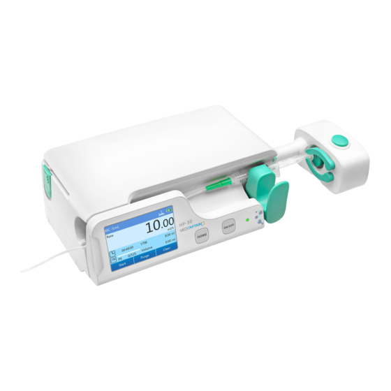
System Overview System Overview Intended Use This product is intended to be used in conjunction with the syringe to control the dose of liquid infused into the patient’s body in clinical departments. Composition Main unit + handle + pole clamp + power cable + nurse caller (optional) Appearance a) Front view 1 –... -
Page 12: Accessories
Barcode scanner MP-4 1454-00022-66 PCA controller 1202-00161-01 Product Specifications Name Syringe pump Model HP-30 Dimensions 258 (W) x 75(H) x 152(D)mm Weight About 1.7kg (including the battery) Operating Temperature: 5° C~40° C Conditions Humidity: 15%~95% RH, non-condensing Pressure altitude: 57.0~106.0kPa... - Page 13 Product Specification Storage and Temperature: -20° C~+55° C Shipping Humidity: 10%~95% RH, non-condensing Conditions Pressure altitude: 22.0~107.4kPa Service Life 10 years 1. Class I / Internally powered equipment; Classification 2. Type CF applied part; 3. IP23; 4. Not sterilized; 5. Not category AP / APG equipment; 6.
- Page 14 Product Specification workstation for communication through the RS-232 protocol, and also used for DC power input. ⚫ RJ45 network port: 10/100 Mbps self-adaptive Ethernet port. ⚫ WiFi network port: Used to communicate with the infusion workstation through the 802.11-b/g/n protocol. Infusion Rate 0.1~60.00(ml/h) (2ml syringe) 0.1~90.00(ml/h) (3ml syringe)
- Page 15 Product Specification (0.10~20.00)ml (20ml syringe) (minimum increment: 0.01ml) (0.10~30.00)ml (30ml syringe) (minimum increment: 0.01ml) (0.10~50.00)ml (50ml/60ml syringe) (minimum increment: 0.01ml) Anti-Bolus Anti-bolus function, unintended bolus ≤ 0.2 ml KVO Rate 0.10~5.00ml/h (minimum increment: 0.01ml/h) Infusion accuracy ≤ ±2% Infusion Accuracy Occlusion Patient side occlusion: 150~975mmHg Level...
-
Page 16: Hardware
–Collateral Standard : Electromagnetic disturbances –Requirements and tests Hardware Circuit Block Diagram Figure 4 shows the circuit block diagram of the HP-30 syringe pump. The components of the HP- 30 syringe pump are described in the following sections. - Page 17 Hardware Description 50pin J1 Door plate Battery 3pins AC-DC AC socket AC power 2PIN 2PIN Power cable 2pin Speaker Detection board for 3pins closed consumable 16pin Size sensor 3pins 4pins G micro USB board Main board 4pins Step Motor Clutch board E nut position Pressure sensor 4pins...
-
Page 18: Power Board
Main Control Board a. Circuit description: The HP-30 main board integrates the power system, main control system, communication circuit and interface, motor drive control circuit, and pressure detection circuit. The specific functions are as follows: Power system: The power system consists of the battery and charging circuit, voltage conversion circuit, and backup alarm circuit. -
Page 19: Key Pad Board
Used for connection to the trip trip potentiometer potentiometer. Socket for connection to Used for connection to USB2.0. USB2.0 HP-30 Key Pad Board a. Circuit description: (1) Display function: A 3-inch color LCD display with a touch screen is used, whose resolution is 480x320 pixels. -
Page 20: Clutch Board
Used for connection to J3 of the board main board through an FFC. HP-30 Clutch Board b. Circuit description: The main functions are as follows: Pressure sensor signal processing: This board inputs, amplifies, and filters the signal of the pressure sensor and then outputs the signal to the main board. -
Page 21: Nut Detection Board
(reserved). detection board HP-30 Nut Detection Board a. Circuit description: (1) This board is used to connect the main board and drive head board and to transfer signals. (2) A DC motor is used to open or close the clutch, and a potentiometer is used to detect the change status of the clutch. -
Page 22: Distance Potentiometer
Socket for connection to Used for connection to J4 of the LCD LCD main control board main control board. 4.11 Battery Pack a. Description: The HP-30 adopts a 11.34V/2900mA lithium-ion battery pack. b. Main test point: Test Point Name Range Unit... -
Page 23: Sensor Information
Sensor Information Sensor Information This chapter only describes the sensor information related to servicing and test. For the description of other software functions, see the corresponding operation manual. Sensor Information Test Choose HOME>Local Set>Maintenance, input the password 1666, and choose Sensor Info. Motor status test: Select Clockwise or Anticlockwise for the motor, select the start speed of the motor (motor speed setting range: 0.01-150r/s), and check whether you can hear the motor rotation sound. - Page 24 Sensor Information Drive sheet test: When the claw opens, press and hold the drive sheet to check whether the status is displayed as 1, and then release the drive sheet to check whether the status is displayed as 0. If the status does not change or changes incorrectly, the drive sheet detection optocoupler or related connection cable may be damaged or the mechanical baffle fails to shield the optocoupler.
-
Page 25: Maintenance
During the test, if the test results do not meet requirements, a certain functional module of the syringe pump is faulty. In this case, immediate maintenance or replacement must be performed. In case of any other doubts, please contact the after-sales service department of MEDCAPTAIN in time. CAUTION: ◼... -
Page 26: Remove An Internal Battery
Maintenance When the battery always gives a low battery indication or the battery is not installed correctly, a battery check is needed. 6.3.2 Remove an internal battery. ⚫ Turn the power off and disconnect the power cord. ⚫ Use a screwdriver to loosen the battery cover fixing screws at the bottom of the pump. ⚫... -
Page 27: Cleaning And Disinfection
Maintenance ⚫ Please follow local laws to dispose the old battery. 7 Cleaning and Disinfection It is highly recommended that the materials and methods listed in this chapter be used for cleaning and disinfection of the device. If other materials or methods are used, the device may be damaged or its service life may be shortened. -
Page 28: Disinfection
Cleaning and Disinfection cleaning mode for this device. Cleaning procedure: 1. Completely immerse a piece of soft medical gauze in neutral or slightly alkaline detergent solution, wring out the gauze, and then use the gauze to wipe the device surface. 2. -
Page 29: Air Drying And Transportation
Cleaning and Disinfection 3. Wipe all the surfaces of the device in sequence. For the contact time of the disinfectant, see the operation manual of the disinfectant. 4. Ensure that all the edges and corners of the device are completely disinfected. 5. -
Page 30: Calibration
Choose HOME>Local Set>Maintenance, input the password 1666, and choose Device Cali.>Sensor Cali.>Distance Cali. Install the big test tools for HP-30 trip potentiometer calibration into the card slot, put down the holder, push the drive head to the rightmost of the calibration tool, press Calibrate, and verify that the maximum displacement monitoring value is consistent with the specification AD value. -
Page 31: Clutch Potentiometer Calibration
Calibration Home means returning to the initial position. Clutch Potentiometer Calibration Choose HOME>Local Set>Maintenance, input the password 1666, and choose Device Cali.>Sensor Cali.>Clutch Position Cali. Gently push the drive head assembly to the left or right to verify that the drive head does not move, press Start to make the clutch motor reaches the lowest position, press Calibrate, and verify that the calibration value of the clutch potentiometer is consistent with the AD value. - Page 32 Calibration Syringe calibration aims to increase the infusion accuracy of the syringe brands not built in the pump. The parameters to be calibrated include Diameter, Mark Len., and Holder Len. Various data of the user-defined brands is left blank when the pump is delivered. If a user-defined syringe brand is not calibrated, users cannot use it.
- Page 33 Calibration Press Confirm to finish calibration. Method 2: The calibration parameters of the consumable can be manually input. If a brand of consumable is not available, build this brand of consumable according to method 1. Choose HOME>Local Set>Maintenance, input the password 1666, choose Cali. Consum.>Edit Consum.
-
Page 34: Alarms And Troubleshooting
WARNING: ➢ During troubleshooting by service personnel, there is a 100-240V AC high voltage in the HP-30 and the switching power supply circuit may generate a 400V DC high voltage. An accidental touch may cause serious personal injury. Please follow the requirements in related regulations and ensure that the maintenance is performed by professional qualified personnel. -
Page 35: Faults And Troubleshooting
Alarms and Troubleshooting After an alarm is triggered, you can press Silent to silence the alarm. Two minutes later, the alarm sound is given again if the alarm level is middle or high and it still exists. Faults and Troubleshooting The following table lists the alarm message, alarm level, alarm cause, and troubleshooting. -
Page 36: Syringe Pump Faults And Troubleshooting
Alarms and Troubleshooting Alarm Message Alarm Level Alarm Cause Troubleshooting high-viscosity cause and resume the solution infusion. infusion. 3. The system will auto reduce the volume when an occlusion occurs. Press Cancel to exit the Standby End Middle The standby time is out. standby state. - Page 37 Alarms and Troubleshooting Alarm Alarm Alarm Content Alarm Cause Troubleshooting Message Level 1. Check whether the infusion tube is twisted or extruded and whether the retaining needle leaks. 2. Check whether the occlusion level setting is reasonable (an older patient indicates a higher drug liquid viscosity and higher infusion rate, and the occlusion level also needs to be...
- Page 38 Alarms and Troubleshooting 1. Check whether the relay devices are properly connected. Two neighboring pumps 2. Check the USB2.0 interface and involved in the relay related connection cable. Relay failed Relay Failed High communicate improperly 3. Check the main board. (workstation) or fail to communicate 4.
- Page 39 Alarms and Troubleshooting detect the data of 2. Check the drive head board and related connection cable. 3. Check the main board. Holder ERR 1. Check whether the holder is moved. (Holder is Syringe position 2. Check whether the syringe falls off. moved) offset (the holder is The holder is pulled by the...
-
Page 40: Check After Repair
Alarms and Troubleshooting ⚫ For the alarm message ERR 00X, X indicates a character. The specific alarm message may be ERR 001, ERR 002, and etc. ⚫ For all problems related to the potentiometer, judge whether the hardware is faulty. Access the AD value on the Maintenance screen, move the potentiometer, and observe whether the AD value changes to judge whether the sensor and related wires are damaged. -
Page 41: Disassembly And Assembly
Lower shell hole plug PM3*8 cross recessed small pan head machine thread screw Dismantle the hole plug (3) of the HP-30 small cover plate for upgrade and PT2.3*6 pressping screw (2). Dismantle the HP-30 lower shell small cover plate for upgrade (1), and then upgrade the pump software and dismantle the main FFC. -
Page 42: Dismantling The Upper Shell And Battery
10.2 Dismantling the Upper Shell and Battery Name Quantity HP-30 upper shell Battery Lift the upper shell (1) upwards to dismantle it. Note that two fasteners at the front end of the upper shell are connected to the middle plate, and be careful not to break them. -
Page 43: Dismantling The Middle Plate And Lower Shell
FFC, HP-30 speed measuring board connection FFC, and main motor connection cable from the HP-30 main board. Remove the HP-30 Micro USB board connection cable from the HP-30 speed measuring board. Remove the ground cable connection cable that is connected to the drive assembly. -
Page 44: Dismantling The Trip Potentiometer
+spring washer+flat washer assembly PM2*14 cross recessed small pan head machine thread screw HP-30 full-trip resistance-type position sensor Remove screws 1 and 2 that fasten the trip potentiometer. Remove the connection cable of the trip potentiometer from the main board, and take down the... -
Page 45: Dismantling The Specification Potentiometer
Remove the connection cable connector of the specification potentiometer from the speed measuring PCBA of the HP-30. Remove the five pressping screws (2). clamping piece pressing plate (3) of the HP-30, and take down the Take down the specification potentiometer (1) together with cables. -
Page 46: Dismantling The Drive Assembly And Middle Plate Assembly
10.6 Dismantling the Drive Assembly and Middle Plate Assembly Name Quantity HP-30 middle plate assembly HP-30 drive assembly PT3*8 cross recessed pan head drilling PT thread pressping screw Remove the six pressping screws (3). Separate the HP-30 drive assembly (2) from the HP-30 middle plate assembly (1). -
Page 47: Dismantling The Pump Door Assembly And Middle Plate Assembly
PT2.3*6 cross recessed pan head drilling PT thread pressping screw HP-30 middle plate assembly Remove the five HP-30 pump door hole plugs (1). Screw out the five pressping screws (2), and lift the pump door cover plate (3) upwards to take down it. -
Page 48: Dismantling The Hp-30 Screen Assembly
Take down the pump door cover plate according to steps 1 and 2 in section 8.7. Remove the pump door board connection FFC (4). Remove the five pressping screws (2), and lift the HP-30 screen assembly upwards to take down it. -
Page 49: Dismantling The Holder
Disassembly and Assembly 10.9 Dismantling the Holder Name Quantity ø 3 snap ring HP-30 specification potentiometer sliding plate HP-30 holder sliding block M3*4 hexagon socket set screw with flat point... - Page 50 Dismantle the snap spring (1), and take down the HP-30 specification potentiometer sliding plate (2). Dismantle the hexagon socket set screw with flat point (4), and take down the HP-30 holder sliding block (3). Pull out the HP-30 holder (9) from the mounting hole of the HP-30 middle plate (7).
-
Page 51: Dismantling The Drive Head Board, Claw Motor, And Pressure Sensor
HP-30 claw motor assembly Remove the three HP-30 drive head hole plugs (5) and three small pan head screw+spring washer assemblies, and take down the drive head rear cover (4). Remove the claw motor connection cable, pressure sensor connection cable, and drive head... - Page 52 (3). Remove the two small pan head screw+spring washer assemblies that fasten the claw motor, and take down the HP-30 claw motor assembly (7). To dismantle only the pressure sensor, ignore steps 2 and 3.
-
Page 53: Dismantling The Nut Displacement Detection Board And Its Connection Ffc
Disassembly and Assembly 10.11 Dismantling the Nut Displacement Detection Board and Its Connection FFC, Clutch Motor, and Drive Head Board Connection FFC... - Page 54 PM1.6*3 cross recessed small pan head machine thread screw HP-30 nut sliding seat HP-30 rack HP-30 gear G4 ø 3 snap ring HP-30 hollow pipe Drive head board connection FFC HP-30 clutch drive lead screw Confidential Information of MEDCAPTAIN MEDICAL TECHNOLOGY CO., LTD. 54/ 82...
- Page 55 Take down the HP-30 clutch drive nut limit shaft (7). Remove the two small pan head screws (13) from the HP-30 clutch drive nut (11), and take down the clutch nut sliding plate (12).
-
Page 56: Dismantling The Speed Measuring Board And Its Connection Ffc, Synchronous
Synchronous cog belt HP-30 synchronous pulley distance sleeve HP-30 speed measuring encoding disk ø 1.5 snap ring HP-30 jokey pulley of synchronous pulley HP-30 main motor assembly Confidential Information of MEDCAPTAIN MEDICAL TECHNOLOGY CO., LTD. 56/ 82... -
Page 57: Dismantling The Ac-Dc Board And Micro Usb Board
Remove the only combination screw fastening the HP-30 speed measuring encoding disk (7), and then take down the speed measuring encoding disk (7) and synchronous pulley distance sleeve (6) in sequence. Remove the snap ring (8), and then take down the HP-30 jokey pulley of synchronous pulley (9). Take down the synchronous cog belt (5). -
Page 58: Dismantling The Rear Vertical Shell Assembly, Power Socket, And Loudspeaker
Remove the connector of the DC power supply connection cable from the main PCBA, and remove the connector of the AC power cable from the AC-DC board. Remove the two pressping screws fastening the HP-30 AC shield, and take down the AC shield together with AC-DC module (1) from the lower shell (3). - Page 59 Remove the five pressping screws, and take down the AC socket (6) from the interface socket. Take down the loudspeaker (5), remove the two pressping screws, and take down the AC socket. Confidential Information of MEDCAPTAIN MEDICAL TECHNOLOGY CO., LTD. 59/ 82...
-
Page 60: Dismantling The Main Pcba
Remove the six combination screws (1). Take down the main PCBA (2) together with the main board protection plate (3) and main board shielding case (5). Take down the lower shell assembly. Confidential Information of MEDCAPTAIN MEDICAL TECHNOLOGY CO., LTD. 60/ 82... -
Page 61: Dismantling The Fastener Assembly
Take down the fastener seat (3) together with the fastener (4) and shifting block plate pressure spring (5). 10.17 Assembly Perform assembly in the reversed order of the disassembly procedure. When performing assembly, note the following points: Confidential Information of MEDCAPTAIN MEDICAL TECHNOLOGY CO., LTD. 61/ 82... - Page 62 10) When installing the trip potentiometer, install the sliding bar of the potentiometer into the installation slot of the nut sliding block. All wires must be connected correctly and firmly. The wire arrangement must be tidy, and the wires must be bundled and fastened as requested. Confidential Information of MEDCAPTAIN MEDICAL TECHNOLOGY CO., LTD. 62/ 82...
-
Page 63: List Of Spare Parts
HP-30 full-trip separation 1204-00098-01 resistance-type assembly position sensor Section 8.4 Middle HP-30 speed separation 1204-00004-01 measuring PCBA assembly Section 8.12 Middle HP-30 speed separation 1402-00017-01 measuring assembly encoding disk Section 8.12 Confidential Information of MEDCAPTAIN MEDICAL TECHNOLOGY CO., LTD. 63/ 82... - Page 64 HP-30 jokey Middle pulley of separation 1404-00023-01 synchronous assembly pulley Section 8.12 Middle separation 1404-00099-01 HP-30 gear G4 assembly Section 8.11 Middle HP-30 drive lead separation 1401-00036-01 screw assembly Section 8.11 Confidential Information of MEDCAPTAIN MEDICAL TECHNOLOGY CO., LTD. 64/ 82...
- Page 65 1202-00063-01 motor assembly assembly Section 8.11 Middle HP-30 syringe size separation 1202-00133-01 potentiometer assembly (with cable) Section 8.5 Middle HP-30 clamping separation 1404-00079-01 piece pressing assembly plate Section 8.5 Confidential Information of MEDCAPTAIN MEDICAL TECHNOLOGY CO., LTD. 65/ 82...
- Page 66 HP-30 AC power Bottom shell 1462-00008-01 supply connection assembly cable Section 8.14 Bottom shell Power socket 1405-00023-01 assembly sealing gasket Section 8.14 Bottom shell 1404-00085-01 AC socket assembly Section 8.14 Confidential Information of MEDCAPTAIN MEDICAL TECHNOLOGY CO., LTD. 66/ 82...
- Page 67 HP-30 main board 1412-00001-01 assembly protection plate Section 8.15 Bottom shell HP-30 main 1204-00037-01 assembly PCBA (with WiFi) Section 8.15 HP-30 main Bottom shell 1204-00068-01 PCBA (without assembly WiFi) Section 8.15 Confidential Information of MEDCAPTAIN MEDICAL TECHNOLOGY CO., LTD. 67/ 82...
- Page 68 Drive head HP-30 pressure 1202-00136-01 assembly sensor (with cable) Section 8.10 Drive head HP-30 claw gear 1404-00027-01 assembly pressing plate Section 8.10 Drive head 1403-00010-01 HP-30 left claw assembly Section 8.10 Confidential Information of MEDCAPTAIN MEDICAL TECHNOLOGY CO., LTD. 68/ 82...
- Page 69 HP-30 pressure 1404-00028-01 assembly seat end cover Section 8.10 Drive head HP-30 drive head 60Z0000054 assembly hole plug Section 8.10 HP-30 pump door Door 1202-00067-01 cover plate assembly assembly Section 8.7 Confidential Information of MEDCAPTAIN MEDICAL TECHNOLOGY CO., LTD. 69/ 82...
- Page 70 HP door spindle Door 1202-00068-01 pressing plate and assembly foam Section 8.7 Door HP-30 front panel 1202-00069-01 assembly assembly Section 8.8 Door HP-30 door 1401-00011-01 assembly spindle sleeve Section 8.7 Confidential Information of MEDCAPTAIN MEDICAL TECHNOLOGY CO., LTD. 70/ 82...
- Page 71 List of Spare Parts Door HP-30 door 1401-00038-01 assembly spindle Section 8.7 Note: The list of spare parts is updated as requested based on product changes and maintenance at regular intervals. Confidential Information of MEDCAPTAIN MEDICAL TECHNOLOGY CO., LTD. 71/ 82...
-
Page 72: Software Upgrade
Connect the white end of the USB-to-RS232 connection cable to the USB port of PC. If it shows the words [com already open, waiting connected to the pump], it means that the cable Confidential Information of MEDCAPTAIN MEDICAL TECHNOLOGY CO., LTD. 72/ 82... - Page 73 Check the baudrate : 230400; Connect the black end of the USB-to-RS232 connection cable to the external USB port of the HP-30/HP-60 rear panel assembly. Restart the integrated machine or power on the board. The system displays a message indicating that the connection is successful.
- Page 74 Software Upgrade Click add, and select the bin file for loading. Select the port on the left, and select the bin file to be programmed on the right. Click start download. A download progress bar is displayed. It takes about 20 minutes for programming of the “main program resource”.
- Page 75 After downloading is completed, a message is displayed to indicate that the downloading is successful. 10) Remove the USB cable from the machine. Note: The cable connected to the PC must not be removed. Otherwise, the PC may break down or restart. 11) Restart the machine.
-
Page 76: Appendix Ⅰtest Equipment And Special Tools
Appendix Appendix ⅠTest Equipment and Special Tools Long screwdriver with Philips head,Diameter Φ5mm, Length > 120mm. Standard screwdriver with Philips head (Diameter Φ3mm, All length is ok) Soldering iron with sharp pointed tip Tweezers... - Page 77 Appendix 5. Common pliers (small size preferred) Electronic scale (500g/0.01g)
-
Page 78: Appendix Ⅱchecklist For Technical Safety Check (Tsc)-Every 24 Months
If the product fails to pass the electrical safety test, contact the after-sales service personnel of Medcaptain. □ Check that no crack or □Shell Leakage Current Test □ Check Syringe Unknown... - Page 79 Appendix the……di-di” alarm Connect the tested device to the auxiliary di-di power output socket of the 601 safety sound is given every 15 analyzer through a power cable. seconds, and the red alarm Connect one end of the red test lead to the indicator flashes.
- Page 80 Appendix Connect the tested device to the auxiliary check whether power output socket of the 601 safety following alarm is generated analyzer through a power cable. within 1 minute: Syringe Plug in the 601 safety analyzer, and press occlusion is displayed on the screen, the “di-di-di…di-di”...
-
Page 81: Appendix Ⅲ Checks After Repair
Appendix Appendix Ⅲ Checks After Repair Hospital: Department: Contact person: Phone: Model: Visual Inspection Function inspection □cleanliness □ Locking with other units or station □completeness Switch on with power supply □Damage and faults affecting safety □ self test □ □Audible alarm Damage to and readability of the label □... - Page 82 EU- Representative name: WellKang Ltd EU- Representative address: Suite B, 29 Harley Street LONDONW1G 9QR, England, United Kingdom Telephone: +86-755-26953369 Fax: +86-755-26001651 Postal code: 518055 Website: http://www.medcaptain.com E-mail: info@medcaptain.com © Copyright 2017-2018 MEDCAPTAIN MEDICAL TECHNOLOGY CO., LTD. All rights reserved.
Need help?
Do you have a question about the HP-30 and is the answer not in the manual?
Questions and answers