
Subscribe to Our Youtube Channel
Related Manuals for CEA Qubox 405W PULSE


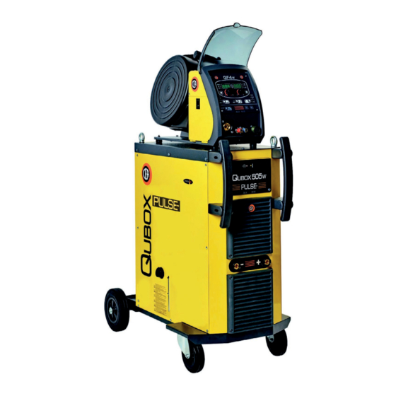
Summary of Contents for CEA Qubox 405W PULSE
- Page 1 ENGLISH CEA COSTRUZIONI ELETTROMECCANICHE ANNETTONI S.p.A. C.so E. Filiberto, 27 - 23900 Lecco - Italy Tel. ++39.0341.22322 - Fax ++39.0341.422646 Cas. Post. (P.O.BOX) 205 E-mail: cea@ceaweld.com - web: www.ceaweld.com...
- Page 2 Thank you for buying our product. In order to get the best performance out of the plant and ensure the maximum lifes- pan of its parts, the use and maintenance instructions contained in this manual must be read and strictly complied with, as well as the safety instructions contained in the relevant folder.
- Page 3 READ Operator’s manual CAREFULLY CEA COSTRUZIONI ELETTROMECCANICHE ANNETTONI S.p.A. C.so E. Filiberto, 27 - 23900 Lecco - Italy Tel. ++39.0341.22322 - Fax ++39.0341.422646 Cas. Post. (P.O.BOX) 205 E-mail: cea@ceaweld.com - web: www.ceaweld.com...
-
Page 4: Table Of Contents
ENGLISH Innovative, technologically advanced, robust, and easy to use, Introduction they can be used for very high quality MIG-MAG and Pulse MIG welding for all materials and especially stainless steel and alu- Description minium, reducing repeat work due to spray to a minimum, using Operating features electrodes, and in TIG with “Lift”... -
Page 5: Special Processes For Qubox Pulse
0,030 Ω Qubox 405w pulse - 0,020 Ω Qubox 505w pulse at the interface point between the user’s supply and the public system. It is the responsibility of the installer or user of the equipment to ensure, by consultation with the distribution network operator if necessary, that the equipment is connected only to a supply with maximum permissible system impedance Z less than or equal to 0,030 Ω... -
Page 6: Ambient Conditions
The welding unit is characterized by the following classes: Ambient conditions • IP 23 S protection class indicates that the generator can be used in both interior and exterior environments. The manufacturer does not accept any responsibility for dam- • The “S” usage class indicates that the generator can be em- age that may result from the plant being used or stored in am- ployed in environments with a high risk of electrical shocks. -
Page 7: Usage Norms
Pos. 9 Quick positive pole connection on the connecting ca- Usage norms ble. Pos. 10 Connector for connecting the interconnection cable. CONTROL APPARATUS (Fig. A) Pos. 11 White LED: signals power supply presence. When it Pos. 1 Front panel. is switched on, the system is powered up and ready Pos. -
Page 8: Mig-Mag Welding / Pulse Mig
The delivery (blue coloured) and return (red coloured) wa- MIG-MAG welding / PULSE MIG ter tubes, used for cooling the torch of the welding machine, are part of the interconnection cable and should be con- To begin MIG-MAG / PULSE MIG welding, carry out the follow- nected as follows: ing tasks (with the machine switched off). - Page 9 2B - Connecting the cables - Welding with a 2) Connect up the earthing system cable to the rapid cou- pling marked by a + (positive) symbol and then the relevant NEGATIVE POLE TORCH (Fig. B2) ground clamps to the piece being welded or to its support in 1) Connect the generator - feeder connection cable using the an area free from rust, paint and grease.
-
Page 10: Spot Welding
4) Open the tap on the cylinder slowly and adjust the reduc- Electrode welding (MMA) er knob to obtain a pressure of about 1,3 to 1,7 bar, and then activate the gas test button and regulate the flow to On the Qubox pulse machine, electrode welding is used to weld a value between 14 and 20 lit/min to suit the current used most metals (different types of steel, etc.) using coated rutilic for welding. -
Page 11: Tig Welding With "Lift
PART TO BE WELDED TIG welding with “Lift” The part to be welded must always be connected to ground in order to reduce electromagnetic emission. Much attention In the TIG process welding is achieved by melting the two met- must be afforded so that the ground connection of the part to al pieces to be joined, with the possible addition of material be welded does not increase the risk of accident to the user or from the outside, using an arc ignited by a tungsten electrode. -
Page 12: Maintenance
Table 6 shows the currents to use with the respective elec- Optional trodes for TIG DC welding. This input is not absolute but is for your guidance only; read the electrode manufacturers’ instruc- NOTE: The digital control unit of the generator is fitted with a tions for a specific choice. -
Page 13: The Pointing Out Of Any Difficulties And Their Elimination
The pointing out of any difficulties and their elimination The supply line is attributed with the cause of the most com- mon difficulties. In the case of breakdown, proceed as follows: 1) Check the value of the supply voltage. 2) Check that the power cable is perfectly connected to the plug and the supply switch. -
Page 14: Wiring Diagram
Wiring diagram Key to the electrical diagram Colour key C-LINK Capacitor Orange-Black Interconnection cable connector Orange Power supply connector for the cooling system Sky Blue Connectors on PCB White Secondary diode Blue Fuse Grey F-EMC EMC filter Yellow Power supply switch Yellow-Green Secondary inductor Brown... - Page 15 2101EC91...
- Page 16 Operator’s manual READ CAREFULLY CEA COSTRUZIONI ELETTROMECCANICHE ANNETTONI S.p.A. C.so E. Filiberto, 27 - 23900 Lecco - Italy Tel. ++39.0341.22322 - Fax ++39.0341.422646 Cas. Post. (P.O.BOX) 205 E-mail: cea@ceaweld.com - web: www.ceaweld.com...
- Page 17 ENGLISH Introduction Introduction Description Thank you for buying our product. In order to get the best performance out of the plant and ensure Technical data the maximum lifespan of its parts, the use and maintenance instructions contained in this manual must be read and strictly Usage limits (IEC 60974-1) complied with, as well as the safety instructions contained Installation...
- Page 18 Persons fitted with pace-makers, hearing aids and similar Usage limits (IEC 60974-1) equipment must consult their doctor before going near a ma- chine in operation. The installation environment of the device The cooling device is sized for cooling by means of water cir- has to be in conformance with the protection degree of the culation in the welder in a continuous manner.
- Page 19 Start-up / drainage Before connecting the equipment to the utilities check the rating plate to make sure the voltage and frequency of the mains correspond and check that the main circuit breaker on the equipment is turnedto “O”. Upon the first usage following a period of extended inactivity of the device or in the case in which the electropump does not go under pressure (slight whistle), it is necessary to undertake drainage in order to eliminate all the air bubbles present within the hydraulic circuit.
- Page 20 Blue Blue...
- Page 21 Maintenance Wiring diagram WARNING: Prior to undertaking any kind of inspection within the machine, unplug the device from feed. • Periodically check the level of the cooling fluid. • Add fluid whenever it drops below the minimum level indi- cated. •...
- Page 22 Lista ricambi LEGGERE ATTENTAMENTE Spare parts list READ CAREFULLY CEA COSTRUZIONI ELETTROMECCANICHE ANNETTONI S.p.A. C.so E. Filiberto, 27 - 23900 Lecco - Italy Tel. ++39.0341.22322 - Fax ++39.0341.422646 Cas. Post. (P.O.BOX) 205 E-mail: cea@ceaweld.com - web: www.ceaweld.com...
- Page 23 Pannello rack Rack panel 438101 438101 Maniglia in fibra Fiber handle 468725 468725 Adesivo logo CEA Ø30mm CEA logo sticker Ø30mm 352362 352362 Alette di aerazione in fibra + sede logo Fiber air-cooling fins + logo housing 403617 403617 Attacco rapido...
- Page 24 18 19 Qubox Qubox Pos. Descrizione Description 405w pulse 505w pulse 622020 622020 Golfare Eyebolt 447720 447720 Guarnizione Gasket 447226 447226 Ancoraggio bombola gas Gas cylinder holder 438720 438720 Manopola interruttore di linea Mains switch knob 468286 468286 Adesivo interruttore di rete Mains switch sticker 427883 427883...
- Page 25 assembly Qubox Qubox Pos. Descrizione Description 405w pulse 505w pulse 435753 435753 Interruttore di linea Mains switch 427667 427667 Filtro EMC EMC Filter 481454 481454 Trasformatore ausiliario Auxiliary transformer 377213 377213 Scheda alimentazioni Power source PCB 413421 413421 Cablaggio ausiliario Auxiliary wiring 413424 413424...
- Page 26 Qubox Qubox Pos. Descrizione Description 405w pulse 505w pulse 486383 486383 Ventilatore 455515 455515 Raddrizzatore secondario Secondary rectifier 478790 478790 Termostato raddrizzatore secondario Secondary rectifier thermostat...
- Page 28 Qubox Qubox Pos. Descrizione Description 405w pulse 505w pulse 418847 418847 Radiatore Radiator 460255 460255 Serbatoio Tank 466467 466467 Tappo serbatoio Tank cap Terminale per connettore maschio Terminal for 3x2 poles male 403783 403783 3x2 vie (lato raffreddamento) connector (water cooler side) Connettore maschio 3x2 vie 403779 403779...
- Page 29 Qubox Qubox Pos. Descrizione Description 405w pulse 505w pulse 451740 451740 Portafusibile Fuse holder 429049 429049 Fusibile Fuse Cablaggio ausiliario per impianto 413385 413385 Auxiliary wiring for water cooler di raffreddamento 403625 403625 Attacco rapido blu Blue quick connection 403632 403632 Attacco rapido rosso Red quick connection...
- Page 30 4) O número de matrícula da própria máquina de soldar EXAMPLE EXEMPLO N. 2 pieces code n. 435753 - for Qubox 405w pulse - 400 V - N° 2 peças código n. 435753 - para o equipamento Qubox 405w 50/60 Hz - Serial number ............
- Page 31 3) Apparatets spenning og frekvens som finnes på merkeplaten for data på apparatet 4) Sveiseapparatets serienummer EKSEMPEL 2 stk. kode 435753 - for apparat Qubox 405w pulse - 400 V - 50/60 Hz - Serienummer..........EL Πααγγελία των αανταλλακτικών Οταν ξητάτε ανταλλκτκά παρακαλείσθε να ημειώνετε καθαρά: 1) τον...
- Page 32 Operator’s manual READ CAREFULLY CEA COSTRUZIONI ELETTROMECCANICHE ANNETTONI S.p.A. C.so E. Filiberto, 27 - 23900 Lecco - Italy Tel. ++39.0341.22322 - Fax ++39.0341.422646 Cas. Post. (P.O.BOX) 205 e-mail: cea@ceaweld.com - web: www.ceaweld.com...
- Page 33 ENGLISH Technical data Introduction Description The general technical data of the system are summarized in ta- ble 1. Technical data Table 1 How to lift up the system Model Opening the packaging Input voltage of wire feeder 24 DC Power output of feeder motor Installation and connections N°...
-
Page 34: Loading Wire
Installation and connections CONNECTION OF THE INTERCONNECTING CABLE BETWEEN WIRE FEEDER AND GENERATOR The extension between the generator and wire feeder consists of a power cable, a multipolar cable for auxiliary power supply and a gas hose which are to be connected to the rear of the wire feeder. •... -
Page 35: Before Welding
TORCH Before welding The torch is subjected to high temperatures and is also stressed by traction and torsion. We recommend not to twist the wire and • Before welding, check that the data on the power source plate not to use the torch to pull the welder. As a result of the above the correspond to the supply voltage and frequency. -
Page 36: Welding Defects
Welding defects Problem Cause Remedy The welder does not supply current • No power • Check that the power cable from the generator to the line and repair if necessary • Torch button does not work • Check that the torch switch gives consensus;... -
Page 37: Wiring Diagram
Wiring diagram 2101FC97... -
Page 38: Key To The Electrical Diagram
Key to the electrical diagram Colour key 17 pin connector for accessories / optional Orange-Black 17 pin connector for remote control connections Sky Blue Drive motor connector White Connectors on PCB Blue Torch connector Grey 24VDC solenoid valve Yellow Membrane keyboard Yellow-Green Ratio-motor Brown... - Page 39 Lista ricambi LEGGERE ATTENTAMENTE Spare parts list READ CAREFULLY CEA COSTRUZIONI ELETTROMECCANICHE ANNETTONI S.p.A. C.so E. Filiberto, 27 - 23900 Lecco - Italy Tel. ++39.0341.22322 - Fax ++39.0341.422646 Cas. Post. (P.O.BOX) 205 e-mail: cea@ceaweld.com - web: www.ceaweld.com...
-
Page 40: Pos
236641 Attacco Euro con tubetto guidafilo Euro connection with wire guide tube 434247 434247 Tubetto guidafilo 61mm 61mm Wire guide tube 420485 420485 Coperchio parte mobile con adesivo logo CEA Movable cover with CEA logo sticker 414326 414326 Chiavistello Latch... -
Page 41: Pos
Quick connection Connettore 14 poli collegamento 14 Pole connector the interconnecting 453146 453146 cavo interconnessione cable connections 403941 403941 Attacco rapido maschio Male quick connection 420484 420484 Coperchio parte fissa con adesivo logo CEA Fixed cover with CEA logo sticker... -
Page 42: Pos
optional Pos. QF4w Descrizione Description 235237 235237 Cavo di potenza Power cable 400000 400000 Adattatore Adaptor 444471 444471 Motoriduttore Drive motor 413379 413379 Cablaggio ausiliario Auxiliary wiring 485040 485040 Tubo gas Gas tube 425987 425987 Elettrovalvola Solenoide valve 377208 377208 Scheda Push Pull (opzionale) Push Pull pcb (option) -
Page 43: Pos
Pos. QF4w Descrizione Description Pag. 6 Pag. 6 Meccanismo di trascinamento Wire feed mechanism assembly 241848 241848 Mozzo bobina Spool holder 377207 377207 Scheda comando motore Motor control PCB 454150 454150 Encoder Encoder 406883 406883 Flangia di guida per pivot Guide flange for pivot 415380 415380... -
Page 44: Pos
IT Complessivo meccanismo di EN Complete entrainment mechanism with 4 rolls trascinamento a 4 rulli 16 15 14 20 21 Pos. Cod. Descrizione Description 307271 Base meccanismo di trascinamento Wire feed mechanism base 437075 Dispositivo di pressione rulli Pressure device 356963 Complessivo leva di pressione sinistra Pressure arm left complete... - Page 45 IT Rulli di trascinamento EN Drive mechanism Rullo inferiore Rullo superiore FILO Diametro filo TWIN kit (doppia cava) Ø37 mm (cava singola) Ø30 mm WIRE Wire diameter Lower roller Upper roller TWIN kit (double slot) Ø37 mm (single slot) Ø30 mm 0,6 ÷...
- Page 46 Operator’s manual READ CAREFULLY CEA COSTRUZIONI ELETTROMECCANICHE ANNETTONI S.p.A. C.so E. Filiberto, 27 - 23900 Lecco - Italy Tel. ++39.0341.22322 - Fax ++39.0341.422646 Cas. Post. (P.O.BOX) 205 E-mail: cea@ceaweld.com - web: www.ceaweld.com...
- Page 47 ENGLISH 3 - WELDING MODE SELECTION Introduction 4 - SPECIAL FUNCTIONS “Fx” SELECTION 5 - PRE-SETTING 6 - WELDING Control panel 7 - HOLD KEY AND KNOB COMMANDS (1/2) KEY AND KNOB COMMANDS (2/2) MIG-MAG manual DISPLAY AND LED INDICATIONS 1 - WELDING PROCESS SELECTION 2 - WELDING MODE SELECTION Switching on the welding machine and initial screen...
-
Page 48: Control Panel
Control panel KEY AND KNOB COMMANDS (1/2) ■ WELDING MODE SELECTION key This is used to select the following welding modes (only for MIG welding processes) and each time the key is pushed the welding machine moves on to se- lect the next welding mode in the following order: TWO STROKE (2T) 2T LED (... -
Page 49: Key And Knob Commands (2/2)
KEY AND KNOB COMMANDS (2/2) ■ SPECIAL FUNCTIONS key “Fx” (T ≥ 2 s) This key is used to display and edit some parame- ters (ADJUSTABLE FUNCTIONS “Fx”) that are nec- essary and fundamental for welding and that have already been set by the manufacturer in the factory. The parameters vary depending on the welding pro- cess and mode used, and are saved in the memory for each automatic welding point (JOB). -
Page 50: Display And Led Indications
DISPLAY AND LED INDICATIONS ■ VRD LED The Voltage Reduction Device (VRD) is a safety device that reduces voltage. It prevents voltages forming on the output terminals that may pose a danger to people. Two-tone LED (off - red - green) indicates enabling of the VRD. -
Page 51: Switching On The Welding Machine And Initial Screen
Switching on the welding Loading of the wire machine and initial screen In the MIG welding processes, with the welder in operation, it is possible to load the wire inside the torch, following this simple At the switching on of the welder (press the switch, located on the procedure: back panel, at the position I), the control performs a short operation • Keep the torch button held down. - Page 52 Table 1 Tabella 1 PROG MiG (MIG SYNERGIC) PLS (PULSE) CLd (vision.COLD) USP (vision.ULTRASPEED) Pow (vision.POWER) PiP (vision.PIPE) SETTINGS RANGE WELDING PROCESS MIG-MAG WELDING MODE MIG MAG / PULSE / FUNCTION DISPLAY Spot Stitch SPECIAL PROCESSES FACTORY RANGE Cycle PROG ADJUSTABLE FUNCTIONS “Fx”...
-
Page 53: Special Functions "Fx
• Rotate the ENCODER - V knob (E2) until the PARAME- Special functions “Fx” TERS DISPLAY - V screen (D2) reads YES. To access the SPECIAL FUNCTIONS “Fx” menu, hold the SPE- CIAL FUNCTIONS “Fx” key (T3) down for at least 3 consecutive seconds. -
Page 54: Timer Arc On
TIMER ARC ON ERROR LOG This indicates the actual time the machine was used for welding. This allows the operator to know about the error states that have arisen on the welding plant. WARNING: This time can only be zeroed using the FACTORY 1) Rotate the ENCODER - A (E1) knob, until both the displays DEFAULT (FAC in the ADVANCE CONFIGURATION menu) for (D1-D2) read Err Log. -
Page 55: Diagnostics
When complete the “Err LoG” message will be displayed. TEST This configuration allows the operator to check that some func- tions of some devices. 1) Rotate the ENCODER - A (E1) knob, until both the displays (D1-D2) read tESt. 4) To go back to the INFO menu, push the PRG/SET (T5) key. 2) Push the PRG key (T5), and the display will show the param- eter to be checked under DISPLAY PARAMETERS - A (D1), and the set-ting under DISPLAY PARAMETERS - V (D2). -
Page 56: Serial Number
SERIAL NUMBER Menu ADVANCE CONFIGURATION This function allows the operator to view the serial number of the interface board. Press the ADV CONFIG key (T ≥ 3 sec) to enter the advanced 1) Rotate the ENCODER - A (E1) knob, until both the displays configuration menu, which provides access to additional features (D1-D2) read SErnUM. -
Page 57: Torch Selection (Gun)
3) Hold the SAVE “MEM” key (T2) down for at least 3 consecu- SAFETY CALIBRATION CODE (SCC) tive seconds. ATTENTION: This operation, if carryed on, optimizes the effi- T ≥ 3 s ciency of the welding circuit (only in MIG welding processes). 4) At this stage the total reset or factory default procedure has To set the length of the welding circuit (adjustable from 1 to 100 m) follow this procedure:... -
Page 58: Torch Calibration (Push Pull)
• Rotate the ENCODER - A (E1) knob until the DISPLAY D1 reads PCB SETTINGS GUn. • Rotate the ENCODER-V (E2) knob until DISPLAY D2 reads oFF - PP 401 d - PP 401 d PLUS - CAL. NO PUSH PULL TORCH MANAGED (DEFAULT) TORCH BINZEL... -
Page 59: Delta Gain
• Display E2 indicates the speed change (expressed in m/min) for MOTOR CALIBRATION (Mot CAL) the wire, for all the regulation scales, in relation to the values at- tributed to the type of torch selected. ATTENTION: This procedure allows you to calibrate the wire • Having set the correct value, push the ADV CONFIG (T6) key. -
Page 60: Arc Length Adjust
• At the end of the procedure, the software present in the welder WATER COOLING MODE will immediately re-calculate the characteristic curve of the en- This configuration allows the operator to set cooling (only if avail- gine, rendering it suitable to use. able), in the following ways: • To exit from the CALIBRATION menu, press and release the • ON DEMAND - In this case, cooling is managed in relation to... -
Page 61: Password
(the operation does not need to be confirmed). 4) To change the PASSWORD, repeat steps 2 and 3. IMPORTANT: If the password is lost, contact CEA’s technical service department. BLOCKS If enabled, this function allows the operator to block or limit use of the welding machine and/or certain welding parameters / functions. -
Page 62: Mig-Mag Synergic / Pulse Mig / Special Processes
2a - SELECTION OF WELDING PROGRAMME (standard MIG-MAG synergic / PULSE method) MIG / Special processes PROGRAM TABLE Start the welder by pressing the switch, located on the back pan- el, at the position I. MIG MAG (MiG MAG) - PULSE (PLS) - VISION.COLD (CLd) - VISION.PIPE (PiP) VISION.POWER (Pou)- VISION.ULTRASPEED (USP) - EXTRA CURVES PACKAGE (ECP) 1 - WELDING PROCESS SELECTION Select the welding PROCESS this way:... -
Page 63: 2B - Selection Of Welding Programme
Select the welding PROGRAMME rotating ENCODER knob - V 2b - SELECTION OF WELDING PROGRAMME (advanced (E2) until obtaining on the PARAMETER DISPLAY screen - V (D2) method) the desired number. This type of programming does not require the use of the feeder’s programs table. -
Page 64: Welding Mode Selection
3 - WELDING MODE SELECTION ■ PROGRAM DEFAULT (dEF) Select the MODE of welding, pressing and releasing, even various times if necessary, the WELDING MODE SELECTION key (T3) WARNING: If carried out, this operation resets the program until the corresponding LED lights up. in use to the factory default settings. -
Page 65: Welding
Example: WIRE SPEED 7 - HOLD Press the PARAMETER SELECTION - A key (T1) until the LED This function automatically starts itself at the conclusion of every that corresponds to the WIRE SPEED switches on. Turn the EN- welding operation and it is indicated to the operator by means of a CODER - A knob (E1) to change the value shown on the PARAM- flashing light of the HOLD FUNCTION LED for a specific amount ETER DISPLAY - A screen (D1). -
Page 66: Mig-Mag Manual
• CRATER START TIME (F10) - This function defines the time MIG-MAG manual in which the current remains at the value of CRATER START SPEED or CRATER START VOLTAGE. Start the welder by pressing the switch, located on the back pan- • CRATER START SLOPE (F11) - Time taken to go from the CRA- el, at the position I. -
Page 67: Pre-Setting
• Hold the SAVE “MEM” key (T2) down for at least 2 consecu- - WELDING VOLTAGE ( ): the measured value of the voltage tive seconds. of what is being welded. - ELECTRONIC INDUCTANCE ( ): the value previously set. During the welding the operator can change the following param- T ≥... -
Page 68: Special Processes
To set the welding machine and make use payment and by request. CEA has designed and developed the of the special processes purchased, the operator must refer following SPECIAL PROCESSES. to the relevant functions and programs table sold with the software. -
Page 69: Special Functions "Fx" Selection
3 - SPECIAL FUNCTIONS “Fx” SELECTION 4 - PRE-SETTING Before welding it is possible to set the following parameters: ADJUSTABLE FUNCTIONS “Fx” Fx > 3s SETTINGS RANGE FUNCTION DISPLAY FACTORY RANGE WELDING CURRENT HOT START 0 ÷ 100 ARC FORCE 0 ÷... -
Page 70: Hold
6 - HOLD This function automatically starts itself at the conclusion of eve- ry welding operation welding and it is indicated to the operator by means of a flashing light of the HOLD FUNCTION LED for a spe- cific amount of time. Once the welding has been terminated, for about 15 seconds, both the DISPLAYS should show the same val- ues of the parameters during the welding. -
Page 71: Pre-Setting
■ PROGRAM DEFAULT (dEF) 4 - WELDING During the welding the display shows: • PARAMETER DISPLAY screen - A (D1) WARNING: If carried out, this operation resets the program in use to the factory default settings. To carry out the reset of the settings / parameters, proceed in the following manner: WELDING CURRENT • Rotate the ENCODER - A (E1) knob until both the displays read... -
Page 72: Job
2 - JOB SELECTION Select the JOB, pressing and releasing, even various times if nec- essary, the WELDING PROCESS SELECTION key (T2) until the 1 - CREATING AND SAVING A JOB corresponding LED lights up. This operation makes it possible to create and save welding set- tings (points) that can be called up by the operator at any time. -
Page 73: Modification And Overwriting Of Amemorised Job
6 - MODIFICATION AND OVERWRITING OF A Error condition MEMORISED JOB To edit and overwrite a JOB proceed as follows: This paragraph describes the error conditions that may arise on 1) Select JOB, pressing and releasing, even various times if nec- the welding machine, the codes and messages shown on both op- essary, the WELDING PROCESS SELECTION key (T2) until erator interface displays, and the diagnoses for attempting to cor-... - Page 74 Error condition Error code Error description and possible diagnosis OVER VOLTAGE E0.2 Automatic reset error. UNDER VOLTAGE E0.3 Automatic reset error. OVER CURRENT E0.4 Automatic reset error. CONFIG. FILE MISSING E1.0 NON automatic reset error. Immediately contact technical assistance dept. USER FILE MISSING E1.1 NON automatic reset error.
- Page 75 CEA COSTRUZIONI ELETTROMECCANICHE ANNETTONI S.p.A. C.so E. Filiberto, 27 - 23900 LECCO - ITALY Cas. Post. (P.O. BOX) 205 Tel. +39 0341 22322 - Fax +39 0341 422646 cea@ceaweld.com www.ceaweld.com...
Need help?
Do you have a question about the Qubox 405W PULSE and is the answer not in the manual?
Questions and answers