Table of Contents
Advertisement
Advertisement
Table of Contents

Related Manuals for Quincy QPNC354

Summary of Contents for Quincy QPNC354
- Page 1 Code 2200780118 Edit. 08/2020 INSTRUCTION AND MAINTENANCE MANUAL DRYERS QPNC354 (E11) - QPNC424 (E12) - QPNC530 (E13) - QPNC636 (E14) (R410A) READ THIS MANUAL CAREFULLY BEFORE CARRYING OUT ANY OPERATIONS ON THE DRYER. Cod. 2200780118 04 - Edition 08/2020 - 1...
-
Page 2: Table Of Contents
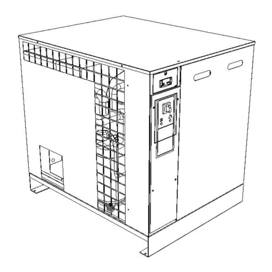
ENGLISH CONTENTS PART A: INFORMATION FOR THE USER GENERAL CHARACTERISTICS INTENDED USE OPERATION GENERAL SAFETY STANDARDS DESCRIPTION OF DANGER SIGNALS DANGER ZONES SAFETY DEVICES POSITION OF PLATES DRYERS ROOM 10.0 TRANSPORT AND HANDLING 11.0 UNPACKING 12.0 INSTALLATION 13.0 DIMENSIONS AND TECHNICAL DATA 14.0 MACHINE ILLUSTRATION 15.0... -
Page 3: General Characteristics
ENGLISH 1.0 GENERAL CHARACTERISTICS The dryer is a chilling machine with direct expansion and dry evaporator. The air to be dried is sent to the heat exchanger in which the water vapour present is condensed: the condensate gathers in the separator and is discharged outside through a steam trap. 2.0 INTENDED USE The dryer has been built to dry the compressed air for industrial use. -
Page 4: Description Of Danger Signals
ENGLISH 5.0 DESCRIPTION OF DANGER SIGNALS 1) Dangerous 2) Air not fit for 3) High pressure 4) Fan rotating 5) Hot parts electricvoltage breathing 6.0 DANGER ZONES 6.1 DANGER ZONES Risks present on the whole machine FIG. 2 7.0 SAFETY DEVICES 7.1 SAFETY DEVICES 1) Cooling fan shield 3) Earth... -
Page 5: Position Of Plates
ENGLISH 8.0 POSITION OF PLATES 8.1 POSITION OF THE DANGER PLATES (Fig. 4) The plates fitted on the compressor unit are part of the machine; they have been applied for safety purposes and must not be removed or spoiled for any reason. Ref.1 - Spare plate Code 1079 9903 48 FIG. -
Page 6: Transport And Handling
ENGLISH 10.0 TRANSPORT AND HANDLING The machine must be transported as shown in the following figures. FIG. 5 MODD. WEIGHT Kg. (lb) 145 (320) 158 (348) 165 (368) 164 (362) 11.0 UNPACKING CUTTING THE METAL STRAPPING IS A DANGEROUS OPERATION, DO NOT ABANDON THE CUT PIECES IN THE ENVIRONMENT. After removing the packing, ensure that the machine is unbroken and that there are no visibly damaged parts. -
Page 7: Installation
ENGLISH 12.0 INSTALLATION 12.1 POSITIONING After unpacking the equipment and preparing the dryers room, put the machine into position, checking the following items: ⚫ ensure that there is sufficient space around the machine to allow maintenance (see Fig. 6). ENSURE THAT THE OPERATOR CAN SEE THE WHOLE MACHINE FROM THE CONTROL PANEL AND CHECK THE PRESENCE OF ANY UNAUTHORIZED PERSONS IN THE VICINITY OF THE MACHINE. -
Page 8: Dimensions And Technical Data
ENGLISH 13.0 DIMENSIONS AND TECHNICAL DATA AIR OUTLET AIR INLET ELECTRICAL CABLE CONDENSATE DRAINING Refrigerant gas 100 (2) TYPE TYPE (mm / in) (mm / in) (mm / in) R-410A 2088 805 (31.7) 1040 (41) 962 (37,87) 2 ”F. 2” F. 805 (31.7) 1040 (41) 962 (37,87) - Page 9 ENGLISH 14.2 DIGITAL CONTROLLER Identification Front panel of the controller Reference Name Alarm icon Refrigerant compressor icon Fan icon Alarm LED Button to snooze or to reset the alarm SET button UP button DOWN buttom Back to previous screen Menu Icons Icon Name...
-
Page 10: Partial Routine Maintenance
ENGLISH PART “B” THIS PART “B” OF THE INSTRUCTIONS MANUAL IS RESERVED FOR PROFESSIONALLY SKILLED PERSONNEL APPROVED THE MANUFACTURER. 16.0 PARTIAL ROUTINE MAINTENANCE BEFORE CARRYING OUT ANY MAINTENANCE JOBS IT IS OBLIGATORY TO STOP THE MACHINE AND DISCONNECT IT FROM THE POWER MAINS AND FROM THE COMPRESSED AIR DISTRIBUTION NETWORK. -
Page 11: Trouble-Shooting And Emergency Remedies
ENGLISH 16.3 CLEANING THE CONDENSER (Fig. 10) The condenser must be cleaned every month. Proceed as follows: - Switch off the machine. Turn the switch in position STOP Ref. 3 Fig. 10 - Turn on the supply automatic differential switch Ref. 4 Fig. 10 - To use the hole Ref. - Page 12 ENGLISH 17.1 REMOTE ALARM FUNCTION The controller allows to remotely visualize a number of alarms. This is managed by two potential free contact NC (Normally Closed).The contacts opens in case of an alarm. - CD contact : it’s in series to all the alarms from the controller ( see the section “fault messages”), to the fan motor breaker Q2, to the phase sequency relay KPH and to the safety pressure switch AP.
- Page 13 ENGLISH Flashing fault message Description Remedy Pressure dewpoint too low. Refer to the fault and remedies section Refrigerant compressor shut down Refrigerant compressor Refer to the fault and remedies discharge temperature too high; section refrigerant compressor stopped. Internal EPROM error Reset by pressing one of the four buttons.
- Page 14 ENGLISH 8. Push and release the UP button (7). 9. Message “y” appears on display. 10. Push and release SET (6) to reset service alarm. 11. Message “y” blinks for 3 seconds. 12. Then “rL” is fixed and “°C” blinks on display for about 10 seconds. The service alarm is now reset.
- Page 15 ENGLISH 9. Then “rS” is fixed and “°C” blinks on display for about 10 seconds. The new service interval is now set. FREEZE PROTECTION FUNCTION Once the digital controller detects a dewpoint temperature below -2°C / 28,4°F during more than 2 minutes, (L2 Alarms), it switches off the refrigerant compressor.
- Page 16 ENGLISH 17.2 REMOTE START/STOP FUNCTION Remove the bridge between A and B and wire a potential free contact in between. The machine will be remotely controlled by the potential free contact, when the main switch is ON. Tag clearly that the machine is remotely controlled ! 1.
- Page 17 ENGLISH PRESSURE DISCHARGE PROCEDURE Proceed as follows: - Close the taps Ref. 1 Fig. 11 - Release the pressure in the dryer by pressing the condensate drain “TEST” pushbutton locate on the steam trap Ref. 1 Fig. 11 - Switch off the machine. Turn the switch in position STOP Ref. 3 Fig. 11 - Turn on the supply automatic differential switch Ref.
Need help?
Do you have a question about the QPNC354 and is the answer not in the manual?
Questions and answers
Our Dryer is not working the fan and the control panel does nothing, it just turns on and nothing else
If the Quincy QPNC354 dryer turns on but the fan and control panel are not working, follow these troubleshooting steps:
1. Check the fan operation – Ensure the fan is functioning correctly. If not, inspect for electrical or mechanical issues.
2. Check the pressostat (pressure switch) – Verify its operation and calibration.
3. Check voltage and power supply – Ensure proper line voltage is available. If the voltage is too low, contact the electric power company.
4. Inspect motor starting system – Check the running and starting relays and any condensers, as a defective starting system may prevent fan operation.
5. Check for refrigerant leaks – If the cooling circuit is not working properly, the fan may not operate. Repair leaks and recharge refrigerant if needed.
6. Check overload protection – If the motor cuts out due to overload, refer to causes such as excessive temperature or improper refrigerant charge.
7. Wait after restart – If the machine was switched off and restarted too quickly, wait a few minutes before trying again to allow pressure balancing.
If the issue persists, contact an authorized technical assistance center.
This answer is automatically generated