
Related Manuals for Noark EX9N-DH-5KT-AU

Summary of Contents for Noark EX9N-DH-5KT-AU
- Page 1 Hybrid Inverter Ex�N-DH-�KT-AU Ex�N-DH-�KT-AU Ex�N-DH-�KT-AU Ex�N-DH-��KT-AU Ex�N-DH-��KT-AU User Manual 07/08/2021 11:11:10 2.00 0.00 Signal -1.39 2.00...
-
Page 2: Table Of Contents
Contents Contents 1. Safety Introductions ………………………………………………… 2. Product instructions 02-04 ………………………………………………… 2.1 Product Overview 2.2 Product Size 2.3 Product Features 2.4 Basic System Architecture 2.5 Maintenance of the System 3. Installation 05-23 …………………………………………………………… 3.1 Parts list 3.2 Mounting instructions 3.3 Battery connection 3.4 Grid connection and backup load connection 3.5 PV Connection 3.6 CT Connection... - Page 3 About This Manual The manual mainly describes the product informa�on, guidelines for installa�on, opera�on and maintenance. The manual cannot include complete informa�on about the photovoltaic (PV) system. How to Use This Manual Read the manual and other related documents before performing any opera�on on the inverter. Documents must be stored carefully and be available at all �mes.
-
Page 4: Product Overview
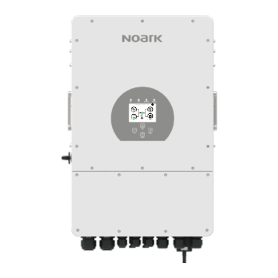
2. Product Introduc�ons This is a mul�func�onal inverter, combining func�ons of inverter, solar charger and ba�ery charger to offer uninterrup�ble power support with portable size. Its comprehensive LCD display offers user configurable and easy accessible bu�on opera�on such as ba�ery charging, AC/solar charging, and acceptable input voltage based on different applica�ons. -
Page 5: Product Size
2.2 Product Size 422.0 mm 450.9 mm Inverter Size 279.0 mm 422.0 mm 254.0 mm 240.00 mm - 03 -... -
Page 6: Product Features
2.3 Product Features - 230V/400V Three phase Pure sine wave inverter. - Self-consump�on and feed-in to the grid. - Auto restart while AC is recovering. - Programmable supply priority for ba�ery or grid. - Programmable mul�ple opera�on modes: On grid, off grid and UPS. - Configurable ba�ery charging current/voltage based on applica�ons by LCD se�ng. -
Page 7: Parts List
3. Installa�on 3.1 Parts List Check the equipment before installa�on. Please make sure nothing is damaged in the package. You should have received the items in the following package: Stainless steel an�-collision Hybrid inverter Wall moun�ng bracket x1 bolt M8×80 Parallel communica�on L-type Hexagon wrench Ba�ery temperature sensor... - Page 8 3.2 Moun�ng instruc�ons Installa�on Precau�on This Hybrid inverter is designed for outdoor use(IP65), Please make sure the installa�on site meets below condi�ons: · Not in direct sunlight · Not in areas where highly flammable materials are stored. · Not in poten�al explosive areas. ·...
- Page 9 ≥500mm ≥500mm For proper air circula�on to dissipate heat, allow a clearance of approx. 50cm to the side and approx. 50cm above and below the unit. And 100cm to the front. Moun�ng the inverter Remember that this inverter is heavy! Please be careful when li�ing out from the package. Choose the recommend drill head(as shown in below pic) to drill 4 holes on the wall, 82-90mm deep.
- Page 10 3.3 Ba�ery connec�on For safe opera�on and compliance, a separate DC over-current protector or disconnect device is required between the ba�ery and the inverter. In some applica�ons, switching devices may not be required but over-current protectors are s�ll required. Refer to the typical amperage in the table below for the required fuse or circuit breaker size.
- Page 11 All wiring must be performed by a professional person. Connec�ng the ba�ery with a suitable cable is important for safe and efficient opera�on of the system. To reduce the risk of injury, refer to Chart 3-2 for recommended cables. Please follow below steps to implement ba�ery connec�on: 1.
- Page 12 3.3.2 Func�on port defini�on Inverter CN1: TEMP: 1,2 CN2: G_start: 1,2 CT_1: 3,4 Parallel_A Parallel_B Meter-485 G_valve: 3,4 CT_2: 5,6 Grid_Ry: 5,6 Modbus CT_3: 7,8 RSD: 7+, 8- 1 2 3 4 5 6 7 8 1 2 3 4 5 6 7 8 Parallel A: Parallel communica�on port 1 (CAN interface).
- Page 13 3.3.3 Temperature sensor connec�on for lead-acid ba�ery Inverter Temp. CT - 11 -...
- Page 14 3.4 Grid connec�on and backup load connec�on · Before connec�ng to the grid, a separate AC breaker must be installed between the inverter and the grid, and also between the backup load and the inverter. This will ensure the inverter can be securely disconnected during maintenance and fully protected from over current.
-
Page 15: Pv Connection
Be sure that AC power source is disconnected before a�emp�ng to wire it to the unit. 3. Then, insert AC output wires according to polari�es indicated on the terminal block and �ghten terminal. Be sure to connect corresponding N wires and PE wires to related terminals as well. 4. - Page 16 Ex9N-DH Ex9N-DH Ex9N-DH Ex9N-DH Ex9N-DH Inverter Model -5KT-AU -6KT-AU -8KT-AU -10KT-AU -12KT-AU PV Input Voltage 550V (160V~800V) PV Array MPPT Voltage Range 200V-650V No. of MPP Trackers No. of Strings per MPP Tracker Chart 3-5 3.5.2 PV Module Wire Connec�on: 1.
- Page 17 Safety Hint: Please use approved DC cable for PV system. Cross section(mm ) Cable type Range Recommended value Industry generic PV cable 4.0~6.0 4.0(12AWG) (model: PV1-F) (12~10AWG) Chart 3-6 The steps to assemble the DC connectors are listed as follows: a) Strip off...
- Page 18 Pic 3.5 connector with cap nut screwed on d) Finally insert the DC connector into the posi�ve and nega�ve input of the inverter, shown as picture 5.6 Pic 3.6 DC input connec�on Warning: Sunlight shines on the panel will generate voltage, high voltage in series may cause danger to life.
-
Page 19: Ct Connection
3.6 CT Connec�on GRID Ground Inverter Black wire White wire 6 7 8 Arrow pointing inverter Grid *Note:when the reading of the load power on the LCD is not correct, please reverse the CT arrow. - 17 -... -
Page 20: Meter Connection
3.6.1 Meter Connec�on GRID Ground Inverter Parallel_A Parallel_B Meter-485 port Three-Phase Smart Meter RS485A Grid RS485B Three-Phase Smart Meter (1,4,7,10) (3,6,9,10) RS 485 CHINT meter CHNT DTSU666 GRID Ground Inverter Parallel_A Parallel_B Meter-485 port RS485B RS485A 1 2 3 4 5 6 7 8 Eastron (1,2,3,4) -
Page 21: Earth Connection(Mandatory)
3.7 Earth Connec�on(mandatory) Ground cable shall be connected to ground plate on grid side this prevents electric shock. if the original protec�ve conductor fails. 3.8 WIFI Connec�on For the configura�on of Wi-Fi Plug, please refer to illustra�ons of the Wi-Fi Plug. The Wi-Fi Plug is not a standard configura�on, it's op�onal. -
Page 22: Wiring System For Inverter
3.10 Wiring System for Inverter - 20 -... -
Page 23: Wiring Diagram
③AC Breaker CT1 CT2 Grid ④AC Breaker Home Load ① DC Breaker for battery Ex9N-DH-5KT-AU: 150A DC breaker Backup Load Ex9N-DH-6KT-AU: 200A DC breaker Ex9N-DH-8KT-AU: 250A DC breaker Ex9N-DH-10KT-AU: 300A DC breaker Ex9N-DH-12KT-AU: 300A DC breaker ② AC Breaker for backup load... -
Page 24: Typical Application Diagram Of Diesel Generator
Ground Inverter ①DC Breaker ③AC Breaker Battery pack ① DC Breaker for battery Ex9N-DH-5KT-AU: 150A DC breaker Remotely control signal line Ex9N-DH-6KT-AU: 200A DC breaker Ex9N-DH-8KT-AU: 250A DC breaker Ex9N-DH-10KT-AU: 300A DC breaker Generator Ex9N-DH-12KT-AU: 300A DC breaker ② AC Breaker for backup load... - Page 25 3.13 Three phase parallel connec�on diagram Max. 10pcs parallel for on-grid and off-grid opera�on. L wire N wire PE wire Inverter No.3 Parallel_A Parallel_B Meter-485 (slave) Ground Inverter ① Inverter ④ ⑤ No.2 (slave) Ground ⑦ ② ⑥ Inverter No.1 (master) Ground ③...
-
Page 26: Operation
4. OPERATION 4.1 Power ON/OFF Once the system has been properly installed and the ba�ery is connected to the inverter, follow the steps below to turn on the inverter: 1. Turn all the breakers of the installa�on on. 2. Turn on the DC switch of the inverter and the power bu�on of ba�ery (If there is one ba�ery installed at the system), no ma�er the order. -
Page 27: Lcd Display Icons
5. LCD Display Icons 5.1 Main Screen The LCD is touchscreen, below screen shows the overall informa�on of the inverter. 05/28/2019 15:34:40 8.30 -3.00 -2.00 3.00 1.The icon in the center of the home screen indicates that the system is Normal opera�on. If it turns into "comm./F01~F64"... - Page 28 5.1.1 LCD opera�on flow chart Solar Page Solar Graph Grid Page Grid Graph Inverter Page Main Screen Battery Page BMS Page Load Page Load Graph Battery Setting System Work Mode Grid Setting System Setup Gen Port Use Basic Setting Advanced Function Device info - 26 -...
-
Page 29: Solar Power Curve
5.2 Solar Power Curve Solar This is Solar Panel detail page. ③ ① ① Solar Panel Genera�on. Power: 1560W Today=8.0 KWH Voltage, Current, Power for each MPPT. ② ② PV1-V: 286V PV2-V: 45V Total =12.00 KWH ③ Solar Panel energy for Day and Total. PV1-I: 5.5A PV2-I: 0.0A PV1-P: 1559W PV2-P: 1W... -
Page 30: Curve Page-Solar & Load & Grid
Li-BMS Mean Voltage:50.34V Charging Voltage :53.2V Batt Total Current:55.00A Discharging Voltage :47.0V Data Mean Temp :23.5C Charging current :50A Total SOC :38% Discharging current :25A Discharge Dump Energy:57Ah Details Data Request Force Charge U:49.58V I:2.04A Request Force Charge: It indicates the BMS requests hybrid inverter to charge Power: 101W the ba�ery ac�vely. -
Page 31: System Setup Menu
5.4 System Setup Menu System Setup This is System Setup page. System Work Mode Battery Setting Gen Port Grid Setting Basic Advanced Device Info. Setting Function 5.5 Basic Setup Menu Basic Setting Factory Reset: Reset all parameters of the inverter. Lock out all changes: Enable this menu for se�ng Time Syncs Beep... -
Page 32: Battery Setup Menu
5.6 Ba�ery Setup Menu Ba�ery capacity: it tells hybrid inverter to know Battery Setting your ba�ery bank size. Batt Mode Use Ba� V: Use Ba�ery Voltage for all the se�ngs (V). Lithium 400Ah Batt Capacity Batt Use Ba� %: Use Ba�ery SOC for all the se�ngs (%). Mode Use Batt V Max A Charge... - Page 33 Generator This page tells generator output voltage, frequency, power. And, how much energy is used from generator. Power: 6000W Today=10 KWH Total =10 KWH P_L1: 2KW V_L1: 230V P_L2: 2KW V_L2: 230V P_L3: 2KW V_L3: 230V Battery Setting Lithium Mode: This is BMS protocol.Please reference the document(Approved Ba�ery).
-
Page 34: System Work Mode Setup Menu
5.7 System Work Mode Setup Menu System Work Mode Work Mode Selling First(Genera�on limit control): This Mode allows 12000 hybrid inverter to sell back any excess power produced Selling First Max Solar Power by the solar panels to the grid. If �me of use is ac�ve, Work Zero Export To Load Solar Sell... -
Page 35: Grid Setup Menu
Energy Pa�ern: PV Power source priority. Ba� First: PV power is firstly used to charge the ba�ery and then used to power the load. If PV power is insufficient, grid will make supplement for ba�ery and load simultaneously. Load First: PV power is firstly used to power the load and then used to charge the ba�ery. If PV power is insufficient, Grid will provide power to load. - Page 36 5.8.2 Grid Standard Selec�on Grid Setting/Grid code selection Grid Mode:General Standard、UL1741 & IEEE1547、 Grid Mode CPUC RULE21、SRD-UL-1741、CEI 0-21、Australia A、 General Standard 0/11 Australia B、Australia C、EN50549_CZ-PPDS(>16A)、 Phase Type Grid Frequency 50HZ Grid NewZealand、VDE4105、OVE-Direc�ve R25. Set1 0/120/240 60HZ Please follow the local grid code and then choose the 0/240/120 corresponding grid standard.
- Page 37 Default volt-var se�ngs for different regions are shown in the following table: Voltage 220V 240V 207V 258V Australia A Inverter maximum ac�ve 44%supplying 60%absorbing power output level(P) % of S rated Voltage 220V 235V 205V 255V Australia B Inverter maximum ac�ve 30%supplying 40%supplying power output level(P) % of S...
- Page 38 Grid Setting/V(W) V(Q) V(W): It is used to adjust the inverter ac�ve power according to the set grid voltage. V(W) V(Q) V(Q): It is used to adjust the inverter reac�ve power according to the set grid voltage. Lock-in/Pn Lock-out/Pn Grid This func�on is used to adjust inverter output power Set5 (ac�ve power and reac�ve power) when grid voltage...
-
Page 39: Generator Port Use Setup Menu
5.9 Generator Port Use Setup Menu GEN PORT USE Generator input rated power: allowed Max. power from diesel generator. Mode GEN connect to grid input: connect the diesel generator to the Generator Input GEN connect to Grid input grid input port. Rated Power PORT Smart Load Output: This mode u�lizes the Gen input connec�on... -
Page 40: Device Info Setup Menu
Advanced Function This is for Wind Turbine DC 1 for WindTurbine DC 2 for WindTurbine 16.5 Wind 0.0A 210V 9.0A Set2 110V 1.5A 230V 10.5A 130V 3.0A 250V 12.0A 150V 4.5A 270V 13.5A 170V 6.0A 290V 15.0A 190V 7.5A 310V 16.5A Advanced Function Ex_Meter For CT: when using zero-export to CT mode,... -
Page 41: Limitation Of Liability
Mode II: With Generator AC cable DC cable Solar Backup Load On-Grid Home Load Grid Battery Generator Mode III: With Smart-Load AC cable DC cable Solar Backup Load On-Grid Home Load Grid Battery Smart Load Mode IV: AC Couple On-Grid+AC couple AC cable DC cable Solar... - Page 42 Error code Description Solutions 1,Check the PV input polarity DC input polarity reverse fault 2,Seek help from us, if can not go back to normal state. 1,The BUS voltage can t be built from PV or battery. DC_START_Failure 2,Restart the inverter, If the fault still exists, please contact us for help 1.
- Page 43 Error code Description Solutions BUS over current. 1, Check the PV input current and battery current setting Tz_HV_Overcurr_fault 2. Restart the system 2~3 times. 3. If the fault still exists, please contact us for help. Remotely shutdown Tz_EmergStop_Fault 1, it tells the inverter is remotely controlled. Leakage current fault 1.
- Page 44 Error code Description Solutions 1,Please check each battery status, such as voltage/ SOC and parameters etc., and make sure all the parameters are same. backup battery fault 2,If the fault still exists, please contact us for help Grid frequency out of range 1.
- Page 45 Under the guidance of our company, customers return our products so that our company can provide service of maintenance or replacement of products of the same value. Customers need to pay the necessary freight and other related costs. Any replacement or repair of the product will cover the remaining warranty period of the product.
-
Page 46: Datasheet
8. Datasheet Model Ex9N-DH-5KT-AU Ex9N-DH-6KT-AU Battery Input Data Ba�ery Type Lead-acid or Lithium-ion Ba�ery Voltage Range(V) 40-60 Max. Charging Current(A) Max. Discharging Current(A) Charging Strategy for Li-ion Ba�ery Self-adap�on to BMS Number of Ba�ery Input PV String Input Data Max. PV Input Power(W) - Page 47 Power Network Monitoring Island Protec�on Monitoring Earth Fault Detec�on DC Input Switch Overvoltage Load Drop Protec�on Residual Current (RCD) Detec�on An�-islanding Protec�on Yes(Ac�ve Frequency Shi�) Surge Protec�on Level TYPE II(DC), TYPE II(AC) Interface Communica�on Interface WIFI, RS485, CAN PV Connec�on VP-D4 General Data Opera�ng Temperature Range...
- Page 48 Model Ex9N-DH-8KT-AU Ex9N-DH-10KT-AU Ex9N-DH-12KT-AU Battery Input Data Ba�ery Type Lead-acid or Lithium-ion Ba�ery Voltage Range(V) 40-60 Max. Charging Current(A) Max. Discharging Current(A) Charging Strategy for Li-ion Ba�ery Self-adap�on to BMS Number of Ba�ery Input PV String Input Data Max. PV Input Power(W) 12000 15000 18000...
-
Page 49: Package And Transport Inverter
Power Network Monitoring Island Protec�on Monitoring Earth Fault Detec�on DC Input Switch Overvoltage Load Drop Protec�on Residual Current (RCD) Detec�on An�-islanding Protec�on Yes(Ac�ve Frequency Shi�) Surge Protec�on Level TYPE II(DC), TYPE II(AC) Interface Communica�on Interface WIFI, RS485, CAN PV Connec�on VP-D4 General Data Opera�ng Temperature Range... - Page 50 11. Appendix I Defini�on of RJ45 Port Pin for BMS 1 2 3 4 5 6 7 8 BMS Port RS485 Pin 485_B 485_A CAN-H CAN-L GND_485 485_A 485_B Defini�on of RJ45 Port Pin for Meter-485 Meter-485 Pin 1 2 3 4 5 6 7 8 Meter-485 Port METER-485-B METER-485-A...
- Page 51 Defini�on of RJ45 Port Pin for DRM Port Modbus port DRM1/5 DRM port 1 2 3 4 5 6 7 8 DRM2/6 DRM3/7 DRM4/8 REF-GEN/0 D-GND NetJ4_7 NetJ4_7 RS232 WIFI/RS232 D-GND 12Vdc WIFI/RS232 This RS232 port is used to connect the wifi datalogger - 49 -...
-
Page 52: Appendix
12. Appendix II 1. Split Core Current Transformer (CT) dimension: (mm) 2. Seconddary output cable length is 4m. Lead Outside Ver: 2.2, 2023-12-13 - 50 -... - Page 53 NOARK Electrics (Shanghai) Co., Ltd. No.���� Sixian Road, Songjiang District, Shanghai, P.R.China services@noark.cn...
Need help?
Do you have a question about the EX9N-DH-5KT-AU and is the answer not in the manual?
Questions and answers