Table of Contents
Advertisement
Quick Links
Advertisement
Chapters
Table of Contents

Summary of Contents for MKN FlexiCombi MagicPilot FKGCOD615
- Page 1 Read the operating instructions prior to commissioning Installation instructions Combisteamer Unit Type of energy Unit type Model FlexiCombi MagicPilot Countertop unit FKGCOD615 FKGCOD621 FKGCOD115 FKGCOD121 Floor-standing unit FKGCOD215 FKGCOD221 10014472-1AIBE-- en-GB...
- Page 2 Fax +49 5331 89-280 Internet www.mkn.eu Copyright All rights to text, graphics and pictures in this documentation are held by MKN Maschinenfabrik Kurt Neubauer GmbH & Co. KG. Distribution or duplication is only permitted with the prior written consent of MKN.
-
Page 3: Table Of Contents
Directory of contents 1 Introduction ................. 5 1.1 About this manual ................ 5 1.1.1 Explanation of signs .................. 6 1.2 Use of the unit ................... 7 1.3 Warranty .................... 7 2 Safety information .............. 8 3 Description of the unit ............. 11 3.1 Overview of the unit ............... 11 3.1.1 Countertop unit ... - Page 4 Directory of contents 6.8 Making the gas connection ............ 43 6.8.1 Description of the gas connection ............ 44 6.8.2 Connecting the gas connection line ............ 44 6.8.3 Checking for leaks ................... 46 6.8.4 Checking the connection pressure ............ 48 6.8.5 Checking the basic gas setting .............. 50 6.8.6 Adjusting the basic gas setting ...
-
Page 5: 1 Introduction
Introduction 1 Introduction 1.1 About this manual The instruction manual is part of the unit and contains information on safe installation of the unit. Observe and adhere to the following instructions: • Read the instruction manual in its entirety prior to installation. •... -
Page 6: Explanation Of Signs
Introduction 1.1.1 Explanation of signs DANGER Imminent threat of danger Failure to comply will lead to death or very severe injuries. WARNING Possible threat of danger Failure to comply can lead to death or very severe injuries. CAUTION Dangerous situation Failure to comply can lead to slight or moderately severe injuries. -
Page 7: Use Of The Unit
Introduction 1.2 Use of the unit This unit is intended to be used solely for commercial purposes, particularly in commercial kitchens. The use of the unit is prohibited in the following countries: • Canada • 1.3 Warranty The warranty is void and safety is no longer assured in the event of: •... -
Page 8: 2 Safety Information
Safety information 2 Safety information The unit complies with applicable safety standards. Residual risks associated with operation or risks resulting from incorrect operation cannot be ruled out and are mentioned specifically in the safety instructions and warnings. The installer must be familiar with regional regulations and observe them. - Page 9 Safety information Organisational measures Risk of property damage and personal injury from lack of organizational measures • Identify hazard areas when transporting, setting up and connecting the unit. • Prior to starting the installation work, notify any operators present about the procedure. •...
- Page 10 Safety information • Prior to working on the gas system, switch off the unit, close the gas supply from the gas system and secure it against being reopened. When bleeding air or degassing, ensure that the air and gas are discharged to the outside in a technically correct manner and without creating a risk.
-
Page 11: 3 Description Of The Unit
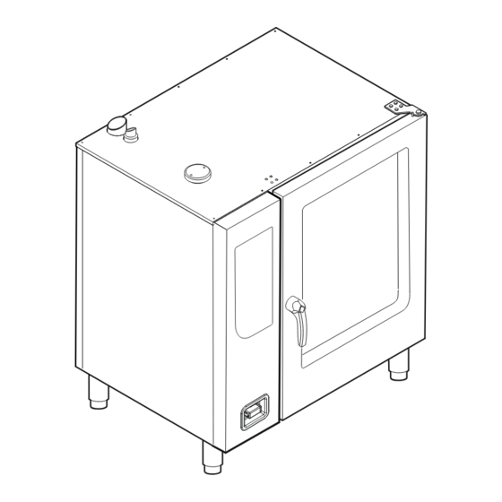
Description of the unit 3 Description of the unit 3.1 Overview of the unit 3.1.1 Countertop unit Image: Unit with tray rack trolley a Tray rack k Nameplate b Insulated window l Base frame (optional) c Door handle m Equipment leg d Cooking zone door n Control unit e Tray rack trolley (optional) -
Page 12: Floor-Standing Unit
Description of the unit 3.1.2 Floor-standing unit Image: Unit with tray trolley a Tray rack k Nameplate b Insulated window l Equipment leg c Door handle m Control unit d Cooking zone door n Housing e Guide rail (right) o Air inlet f Tray trolley p Waste gas connection g Push handle... -
Page 13: Planning Drawing
Description of the unit 3.2 Planning drawing Image: Size 6XX and 1XX Image: Size 2XX Model: FKGCOD Size 615, 621 115, 121 215, 221 1020 1020 1075 1060 1640 1640 1960 All dimensions in mm Installation instructions... -
Page 14: Equipment And Connection Data
Description of the unit 3.3 Equipment and connection data Model: FKGCOD Size Dimensions Unit 1020 x 799 x 790 1020 x 799 x 1060 1075 x 813 x 1960 Length x Width x Height (mm) Weight (kg) unit Emissions Noise level (db(A)) <... - Page 15 Description of the unit Model: FKGCOD Size Type of water Tap water, cold Carbonate hardness < 4 (22) CaCO (mmol/l (°dH)) Connection pressure (kPa (bar)) 200 (2) 600 (6)— Connection (") R 3/4 Water consumption for steaming Soft water (l/h) Water consumption for Combisteaming Soft water (l/h) 10,6...
- Page 16 Description of the unit Model: FKGCOD Size Combustion air (m³/h) ** Supply air routing and exhaust gas routing Required delivery pressure 0 — 5 (Pa) 13BS Exhaust gas temperature (°C) 13BS Exhaust gas mass flow rate (kg/h) 13BS * Information is country-specific and applies to Germany; for further information, see "Checking the connection pressure" ** Information applies at 15 °C and 1013,25 hPa (mbar) Transformer voltage Type of connection...
- Page 17 Description of the unit Basic setting Parameter Standard Adjustment Explanation value range Altitude 0 — 999 0 — 999 m Request the altitude above sea level from the closest weather station. If the altitude 1000 m — 1999 is unknown, set 0 – 999 m. 2000 m — 2499 2500 m or higher Audible signal Medium...
- Page 18 Description of the unit Basic setting Parameter Standard Adjustment Explanation value range Preselect 30 °C — 250 °C Preset temperature for Combisteaming Combisteaming temperature Preselect hot air 30 °C — 250 °C Preset temperature for hot air temperature Preselect 30 °C — 150 °C Preset temperature for regeneration regeneration temperature...
- Page 19 Description of the unit Gas blower speed Model: FKGCOD Gas blower speed (rpm) High output (High) Low output (Low) 5050 * 4800 6700 4800 5050 2800 6700 2800 5050 2800 6700 2800 * Contrary to the table, the gas blower speed on the 615 model is 5500 1/min at the described setting after the rated heat input has been checked.
- Page 20 Description of the unit Model: FKGCOD Natural gas E/ Natural gas LL/ Natural gas L Natural gas K Natural gas Primary air gap (mm) 30 — 50 CO content (ppm) *** < 1000 (optimum < 100) Orifice size (1/100 (mm)) N/A** N/A** N/A**...
-
Page 21: 4 Transporting The Unit
Transporting the unit 4 Transporting the unit CAUTION Risk of property damage and personnel injury from tipping equipment • Do not linger next to or behind raised equipment. • Move raised equipment carefully. ATTENTION Risk of physical damage from improper transport •... -
Page 22: Unpacking The Unit
Transporting the unit 4.2 Unpacking the unit CAUTION Risk of injury from sharp edges • Wear protective gloves. When unpacking the unit, inspect it for transport damage. Do not install damaged units or put into service. 1. Remove the packaging. 2. -
Page 23: 5 Setting Up The Unit
Setting up the unit 5 Setting up the unit Supply air and exhaust gas openings The supply air and exhaust gas openings in the unit must not be obstructed or closed. WARNING Risk of burns from spraying hot fat • Set up deep fat fryers outside the range of the hand shower. -
Page 24: Lifting The Unit Off The Pallet
Setting up the unit The following clearances from walls, ceilings or other equipment must be maintained when setting up the unit: • Left, right and rear at least 50 mm. • For service work, 500 mm on the left is recommended. •... -
Page 25: Setting Up The Unit On The Equipment Legs
Setting up the unit 5.3 Setting up the unit on the equipment legs Requirement The floor must carry the weight of the unit 1. Lift the unit with the pallet truck. 2. Move the unit to the installation site. 3. Place the unit on the floor. 4. -
Page 26: Installing The Support Rack
Setting up the unit Image: Attach a warning sign about the shelf height 3. Clean the adhesive surface for the sticker. 4. Attach the sticker to the cooking zone door at a height of 1,6 m. 5.4.1 Installing the support rack Depending on the version, the base frame can be equipped with a support rack. -
Page 27: Aligning The Unit
Setting up the unit 5.5 Aligning the unit 5.5.1 Aligning countertop units Requirement Base frame levelled Level the unit by screwing the equipment legs in or out. Fill out the Commissioning report. 5.5.2 Aligning floor-standing units ATTENTION Risk of water discharge from leaking cooking zone The cooking zone will leak if the tray trolley is not aligned. - Page 28 Setting up the unit Image: Aligning the tray trolley with the insertion system a Tray trolley d Equipment leg b Distance e Support roller c Guide rail f Push handle 1. Level the unit by screwing the equipment legs in or out. 2.
-
Page 29: 6 Connecting The Unit
Connecting the unit 6 Connecting the unit DANGER Risk of personal injury and physical damage from electric shock • Prior to working on the unit, ensure that the unit has been disconnected from the mains. • Do not operate the unit with the housing open. CAUTION Risk of injury from sharp edges •... -
Page 30: Checking The Supply Air Routing And Exhaust Gas Routing
Connecting the unit Attaching the side wall ATTENTION Risk of physical damage from leaky housing • Check seals when attaching the housing parts. • Replace damaged gaskets. 1. Insert the top edge of the side wall. 2. Carefully push the bottom of the side wall inwards. 3. - Page 31 Connecting the unit – Type B unit: Direct routing of exhaust gas via ventilation system or chimney or indirect routing of exhaust gas via ventilation systems such as ventilated ceiling or ventilation hood. 13BS Image: Indirect exhaust gas routing a Ventilation hood d Flow control b Steam outlet connection fitting e Exhaust gas duct...
-
Page 32: Making The Power Connection
Connecting the unit 6.3 Making the power connection The unit must be connected on the basis of the information on the nameplate and this manual. ATTENTION Risk of physical damage from incorrect connection voltage • Before making the connection, measure the connection voltage and check the set voltage on the transformers in the unit. - Page 33 Connecting the unit Plug-in connection CAUTION Risk of property damage and personal injury from improper installation • The plug-in connection must be readily accessible. If the unit is connected with a plug to the power-supply mains, use plugs and sockets according to IEC60309. The socket must be readily accessible so that the unit can be disconnected from the electric mains at any time.
-
Page 34: Matching The Unit To The Connection Voltage
Connecting the unit 6.3.1 Matching the unit to the connection voltage DANGER Risk of personal injury and physical damage from electric shock • Prior to working on the unit, ensure that the unit has been disconnected from the mains. • Do not operate the unit with the housing open. -
Page 35: Connecting The Power Connection Cable
Connecting the unit 230 V 220 V 200 V 120 V N -20 V N 20 V Image: A Transformer position T2, T3; B Connection for transformer glow electrode Requirement Unit not live Left side wall removed 1. Measure the connection voltage with a suitable measuring device. The voltage range must match that on the nameplate. - Page 36 Connecting the unit DANGER Risk of personal injury and physical damage from electric shock • Before connecting, ensure that the power connection cable has been disconnected from the power supply. • Ensure that the power connection cable is undamaged. Image: Connecting the electric power cable a Connection terminals c Electric power cable b Cable tie...
-
Page 37: Connecting To The Potential Equalisation Circuit
Connecting the unit 6.3.3 Connecting to the potential equalisation circuit Image: Connecting the potential equalisation circuit 1. Run and attach potential equalisation line to the identified terminal. 2. Fill out the commissioning report. 6.4 Connecting the kitchen management system The units can be connected with a RJ45 plug to a kitchen management system. - Page 38 Connecting the unit Image: Connecting the kitchen management system a RJ45 socket d Cable tie b RJ45 plug e Ferrite ring c Network cable Requirement Unit not live Housing opened 1. Pull the network cable into the unit through the cable gland. 2.
-
Page 39: Making The Basic Control Setting
Connecting the unit 6.5 Making the basic control setting Image: Main menu a Main menu d "Equipment functions" button b FlexiHelp button e Back button c Language selection 6.5.1 Changing the basic control setting By entering the password "2100", the basic settings for the installation can be displayed and changed. -
Page 40: Making The Water Connection
Connecting the unit 6.6 Making the water connection Installation work involving drinking water must be performed by an authorised plumbing contractor. Observe applicable regional regulations with regard to drinking water installations and connection data (see "Equipment and connection data"). The unit has a connection for permanent attachment the drinking water system. -
Page 41: Connecting Softened Tap Water To Both Connections
Connecting the unit Requirement Water pressure complies with the specified range (see "Equipment and connection data") Backflow preventer installed The connection lines are pressure-tight and suitable for tap water 1. Connect the connection lines to the tap water valves using seals. 2. -
Page 42: Making The Wastewater Connection
Connecting the unit 6. Open the tap water valve and check the threaded connectors for leaks. 7. Fill out the Commissioning report. 6.7 Making the wastewater connection Installation work involving wastewater must be performed by an authorised plumbing contractor. Observe the applicable regional regulations of the sewage utility involved. -
Page 43: Making The Gas Connection
Connecting the unit 6.8 Making the gas connection DANGER Risk of fatal injury from operating the unit with the wrong gas type • Ensure that the gas type for which the unit is set (see gas type supplemental label) matches the gas type available at the site. -
Page 44: Description Of The Gas Connection
Connecting the unit Permanent connection The unit is intended for a permanent connection. The connection line must be flexible. Route the flexible gas connection line or gas hose line in accordance with the manufacturer's information and without it being stressed, kinked or twisted. Shut-off device The unit or the gas connection line must be equipped with a thermally activated shut-off. -
Page 45: Switch Off The Unit
Connecting the unit Requirement Gas shut-off valve closed Unit not live Left side wall removed 1. Connect the unit to the gas connection line. ATTENTION Risk of physical damage from excessively high pressure • When opening the gas shut-off valve on the unit, ensure that the pressure in the gas connection line is <... -
Page 46: Checking For Leaks
Connecting the unit 6.8.3 Checking for leaks DANGER Risk of personal injury and physical damage from electric shock • Inspection and adjustment work that can be carried out only with the housing open and the unit under power must be performed only by electrically trained technical personnel. -
Page 47: The Unit Operates At Full Load
Connecting the unit 4. Using the left knob, set the burner to high output ("HI"). The left display flashes "HI". The centre display shows "CO2". 5. Using the right knob, select the first burner "-1-" (on models with two burners). The right display flashes "-1-". -
Page 48: Checking The Connection Pressure
Connecting the unit 6.8.4 Checking the connection pressure DANGER Risk of personal injury and physical damage from electric shock • Inspection and adjustment work that can be carried out only with the housing open and the unit under power must be performed only by electrically trained technical personnel. - Page 49 Connecting the unit DANGER Risk of explosion and fire from escaping gas • When bleeding air from or degassing the gas system and the unit, ensure that the air and gas are discharged to the outside in a technically correct manner and without creating a risk.
-
Page 50: Checking The Basic Gas Setting
Connecting the unit 6.8.5 Checking the basic gas setting DANGER Risk of personal injury and physical damage from electric shock • Inspection and adjustment work that can be carried out only with the housing open and the unit under power must be performed only by electrically trained technical personnel. - Page 51 Connecting the unit Image: CO2 setting a Cooking zone (burner) d Output b Flame status detected e Gas blower speed c Gas demand status f Cooking zone temperature Image: Size 2XX a Burner 1 (cooking zone 1) b Burner 2 (cooking zone 2) Installation instructions...
-
Page 52: Measure The Exhaust Gas Values In The Waste Gas Connection With An Approved Exhaust Gas Measuring Device, While The Unit Is At A Warm Operating Temperature
Connecting the unit Checking the rated heat input at full load Image: Measurement in the exhaust gas a Exhaust gas measuring device c Waste gas connection for burner 2 (only size 2XX) b Waste gas connection, burner 1 d Steam outlet 1. - Page 53 Connecting the unit 11.Press the Back button twice. The main menu appears. 12.Switch off the unit. 13.Fill out the Commissioning report. Checking the rated heat input at partial load Image: Measurement in the exhaust gas a Exhaust gas measuring device c Waste gas connection for burner 2 (only size 2XX) b Waste gas connection, burner 1...
- Page 54 Connecting the unit 9. On models with two burners: Repeat the procedure for the second burner. 10.Press the "Stop" button. The flame goes out. The burner is off. 11.Press the Back button twice. The main menu appears. 12.Switch off the unit. 13.Fill out the Commissioning report.
- Page 55 Connecting the unit 3. Check whether the measured primary air gap is within the specified range (see "Equipment and connection data"). If the measured primary air gap is not in the specified range, adjust the primary air quantity (see "Adjusting the basic gas setting").
- Page 56 Connecting the unit Image: Measurement in the exhaust gas a Exhaust gas measuring device c Waste gas connection for burner 2 (only size 2XX) b Waste gas connection, burner 1 d Steam outlet Requirement Gas connection line connected Checked for leaks outside the unit Connection pressure checked Checked for leaks inside the unit Rated heat input checked...
-
Page 57: Adjusting The Basic Gas Setting
Connecting the unit 10.Press the Back button twice. The main menu appears. 11.Switch off the unit. 12.Fill out the Commissioning report. 6.8.6 Adjusting the basic gas setting DANGER Risk of personal injury and physical damage from electric shock • Inspection and adjustment work that can be carried out only with the housing open and the unit under power must be performed only by electrically trained technical personnel. -
Page 58: Turning Anti-Clockwise: Co 2 Content Is Increased
Connecting the unit Image: Adjusting the rated heat input a Adjusting screw for partial load (TX40) 1. Switch on the unit. 2. Call up the CO2 setting display (see "Checking the basic gas setting"). 3. Set the "Output" field to low output ("Low"). 4. - Page 59 Connecting the unit 13.Press the "Stop" button. The flame goes out. The burner is off. 14.Press the Back button twice. The main menu appears. 15.Switch off the unit. 16.Fill out the Commissioning report. Adjusting the primary air quantity DANGER Risk of personal injury and physical damage from electric shock •...
- Page 60 Connecting the unit 1. Check the suction hose for position and condition. If the suction hose is routed with kinks, replace the suction hose. If the suction hose is not routed in the shape and position as shown in the figure, correct the position and shape. If the suction hose is damaged, replace it.
- Page 61 Connecting the unit Image: Adjusting screws on the burner a Adjusting screw for partial load b Adjusting screw for full load (TX40) (4 mm Allen key or 1.2 x 6.5 mm screwdriver) Manually adjusting the rated heat input at partial load 1. Switch on the unit. 2.
- Page 62 Connecting the unit 12.Press the Back button twice. The main menu appears. 13.Switch off the unit. 14.Fill out the Commissioning report. Manually adjusting the rated heat input at full load 1. Switch on the unit. 2. Set the unit to high output (see "Checking the basic gas setting"). The unit operates at full load.
- Page 63 Connecting the unit Checking the offset pressure DANGER Risk of personal injury and physical damage from electric shock • Inspection and adjustment work that can be carried out only with the housing open and the unit under power must be performed only by electrically trained technical personnel.
-
Page 64: Converting The Gas Type
Connecting the unit 9. Check whether the measured offset pressure is within the specified range (see "Equipment and connection data"). 10.Press the "Stop" button. The flame goes out. The burner is off. 11.Press the Back button twice. The main menu appears. 12.Switch off the unit. - Page 65 Connecting the unit DANGER Risk of personal injury and physical damage from electric shock • Inspection and adjustment work that can be carried out only with the housing open and the unit under power must be performed only by electrically trained technical personnel. Image: Changing the gas orifice a Burner c Gas solenoid valve...
-
Page 66: Switch Off The Unit
Connecting the unit 9. Fill out the Commissioning report. 10.Connect the unit to the gas connection line (see "Connecting the gas connection line"). ATTENTION Risk of physical damage from excessively high pressure • When opening the gas shut-off valve on the unit, ensure that the pressure in the gas connection line is <... -
Page 67: Making The Exhaust Air Connection
Connecting the unit 6.10 Making the exhaust air connection When setting up the unit under a ventilation system, observe the regional regulations for heating, ventilation and air conditioning systems. ATTENTION Risk of physical damage from fouling of the exhaust air ducts •... -
Page 68: 7 Testing The Function
Testing the function 7 Testing the function DANGER Risk of personal injury and physical damage from unsuccessful operational check • Do not put the unit into service. • Contact customer service. Requirement Power connection made Water connection made Wastewater connection made Supply air routing and exhaust gas routing checked and switched on Gas connection line connected Checked for leaks outside the unit... -
Page 69: Checking The Monitoring Of The Exhaust Gas Routing
Testing the function 6. Switch off the unit. 7. Fill out the Commissioning report. 7.2 Checking the monitoring of the exhaust gas routing 1. Switch on the unit 2. Start any cooking program with the maximum temperature (see Operating instructions). The burner ignites. -
Page 70: Checking The Flame Pattern
Testing the function 4. In the case of models with two burners, set the Cooking zone field to "cooking zone 1" for burner 1. 5. Press the "Start" button. The burner ignites. 6. Observe the ignition behaviour through the inspection opening, until the flame burns stably. -
Page 71: Checking The Flame Monitoring
Testing the function 8. Observe the flame pattern through the inspection opening. The flame must be pointed at its core. The flame must not generate soot, appear yellow, flash back or lift off. 9. Press the "Stop" button. The flame goes out. The burner is off. -
Page 72: Checking The Controls
Testing the function 11.On models with two burners: Repeat the procedure for the second burner. 12.Switch off the unit. 13.Fill out the Commissioning report. 7.6 Checking the controls Requirement Ignition behaviour checked Flame pattern checked 1. Switch on the unit 2. -
Page 73: Running The Self-Diagnosis
Testing the function 7.8 Running the self-diagnosis 1. Switch on the unit. 2. Start the "CombiDoctor" self-diagnosis program (see "Checking the unit" in the Operating instructions). If no errors are displayed, the unit is OK. 3. Switch off the unit. 4. -
Page 74: 8 Putting The Unit Into Service
Putting the unit into service 8 Putting the unit into service If the unit is not put into service immediately after being connected and the function check, all inspections must be repeated. Requirement Supply air and exhaust gas routing checked Power connection made Gas connection made Water connection made... - Page 75 Putting the unit into service Electrical connection Electrical connections made properly? Residual-current protective device connected immediately before this unit? Residual-current protective device connected before this and other units? Connection voltage measured? Connection voltage: _______________ (V) Set transformer voltage T0: 0 V | ______ V | ______ V; T1: blue 0 V | red ______ V; T2/T3: blue ______ V | red ______ V Kitchen management system Has the kitchen management system been connected properly? Basic control setting...
- Page 76 Putting the unit into service Water connection Water connection made properly? Lines and connections leak-tight? Water connections connected with T-piece? Connected only to softened tap water Connected only to tap water Wastewater connection Wastewater connection made properly? Waste trap in the building Aerator Funnel drain Floor gutter...
- Page 77 Putting the unit into service Gas connection Are exhaust gas values at partial load OK? Measured CO : __________ Vol % Set CO : __________ Vol % Measured CO: __________ ppm Set CO: __________ ppm Conversion of gas type (if necessary) Burner nozzle / gas orifice exchanged? Before conversion: After conversion:...
- Page 78 Putting the unit into service Final notes Was the unit put into service? Comments: Operator trained? Electrical installation was provided by: Company Installer City, date Signature The connection to a kitchen management system was made by: Company Installer Place, date Signature Water installation was provided by: Company...
- Page 80 www.mkn.eu...
Need help?
Do you have a question about the FlexiCombi MagicPilot FKGCOD615 and is the answer not in the manual?
Questions and answers