
Summary of Contents for Pfeiffer Vacuum RC 500
- Page 1 OPERATING INSTRUCTIONS Translation of the Original RC 500 ∣ RC 500 WL Remote control...
- Page 2 Dear customer, Thank you for choosing a Pfeiffer Vacuum product. Your new remote control is designed to support you with its performance, perfect operation and without impacting your individual application. The name Pfeiffer Vacuum stands for high-quality vacuum technology, a comprehensive and complete range of top-quality products and first-class service.
-
Page 3: Table Of Contents
Making ready for operation Switching off the remote control 6.2.1 Selecting the leak detector type 6.2.2 Selecting and connecting a leak detector (RC 500 WL) Changing the leak detector type Change the selection of the leak detector (RC 500 WL) - Page 4 Table of contents 7.3.4 Configuring energy saving settings (RC 500 WL) Perform settings for the measurement 7.4.1 Setting the threshold value (Trigger) 7.4.2 Setting the measured value display 7.4.3 Setting the scale of the Q(t) axis 7.4.4 Setting the scale of the time axis...
- Page 5 List of tables List of tables Tbl. 1: Related documents Tbl. 2: Cable-bound connection Tbl. 3: Wireless connection 5/50...
- Page 6 List of figures List of figures Fig. 1: Top and bottom view Fig. 2: Connections on the right side and bottom Fig. 3: Mounting the radio transmitter and remote control on the leak detector Fig. 4: Available devices on the touch screen Fig.
-
Page 7: About This Manual
The part number is found on the rating plate of the product. Pfeiffer Vacuum reserves the right to make technical changes without prior notification. The figures in this document are not to scale (dimensions in mm). -
Page 8: Conventions
About this manual 1.3 Conventions 1.3.1 Instructions in the text Usage instructions in the document follow a general structure that is complete in itself. The required ac- tion is indicated by an individual step or multi-part action steps. Individual action step A horizontal, solid triangle indicates the only step in an action. ►... -
Page 9: Safety
Safety instructions according to product’s life stages All safety instructions in this document are based on the results of a risk assessment. Pfeiffer Vacuum has taken into account all the relevant life stages of the product. Risks during transport NOTICE... - Page 10 Safety Risks during installation DANGER Danger to life due to electric voltage High voltages are present inside the device. When touching parts that are live, there is a risk of death. ► Disconnect the device from the current supply before performing all installation and maintenance work.
- Page 11 ► Only operate the device in a dry environment. ► Operate the device away from fluids and humidity sources. ► Do not switch on the device if fluid has penetrated into it, instead contact Pfeiffer Vacuum Serv- ice. ► Always disconnect the current supply before cleaning the device.
- Page 12 ► Operate the device away from fluids and humidity sources. ► Take special precautions if there is a risk of dripping water. ► Do not switch on the device if fluid has penetrated into it, instead contact the Pfeiffer Vacuum Service Center.
- Page 13 Safety NOTICE Undetected leaks from interrupted connection If the connection to the remote control fails, the measurement of the leak detector is not interrupted. As a result, leaks remain undetected. ► Check the connection status at regular intervals. NOTICE Undetected leaks due to missing knowledge of the leak detector Operation of the leak detector via the remote control without full knowledge of the leak detector may lead to malfunctions and undetected leaks.
-
Page 14: Safety Precautions
Safety Risks when shipping WARNING Risk of poisoning from contaminated products Where products that contain harmful substances are shipped for maintenance or repair purposes, the safety of service personnel is at risk. ► Comply with the instructions for safe shipping. Risks during disposal CAUTION Health hazard caused by environmentally hazardous substances... -
Page 15: Foreseeable Improper Use
● Use with replacement or accessory parts that are unsuitable or are not approved 2.6 Responsibilities and warranty Pfeiffer Vacuum shall assume no responsibilities and warranty if the operating company or a third party: ● disregards this document. ● does not use the product for its intended purpose. -
Page 16: Personnel Qualification For Maintenance And Repair
─ Customer with Pfeiffer Vacuum service training ─ Pfeiffer Vacuum service technician 2.8.3 Advanced training with Pfeiffer Vacuum For optimal and trouble-free use of this product, Pfeiffer Vacuum offers a comprehensive range of courses and technical trainings. For more information, please contact Pfeiffer Vacuum technical training. -
Page 17: Transportation And Storage
Transportation and storage 3 Transportation and storage NOTICE Damage caused by incorrect transportation Transportation in unsuitable packaging, or failure to install all transport locks, can damage the prod- uct. ► Comply with the instructions for safe transportation. NOTICE Damage caused by improper storage Improper storage will lead to damage to the product. -
Page 18: Product Description
Part number PT 445 420 - PT 445 432 - PT 445 421 - Designation of the remote control RC 500 WL RC 500 WL RC 500 Data cable RJ-25/Sub-D Data /current supply cable RJ-25/RJ-25 Charge adapter for integrated rechargeable battery... -
Page 19: Components
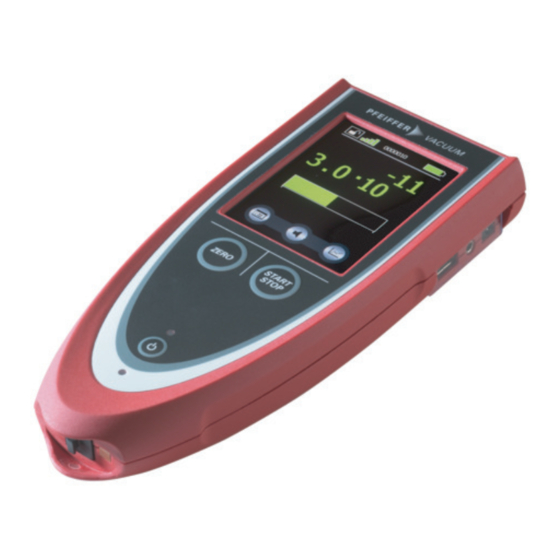
Product description 4.3.1 Components Fig. 1: Top and bottom view 1 "ON/OFF" button LED "Charge" Switches the device or display on or off Illuminates when the rechargeable battery of the device is being charged 2 "ZERO" button Magnets Activates the suppression of the underground For securing quickly to metallic surfaces signal in measuring mode 3 Touchscreen... -
Page 20: Charge Adapter (Rc 500 Wl)
2 3.5 mm jack for connecting a headset RJ-25 socket for a cable connection to the leak detector 4.3.3 Charge adapter (RC 500 WL) You can use the charge adapter worldwide as you can change the plug. See "Technical data" (see chapter “Technical data”, page 44) -
Page 21: Installation
Connecting the remote control RC 500 You can connect the cable-bound remote control RC 500 directly to the leak detector using the connect- ing cable. The connecting cable transfers the data and supplies the remote control with voltage. A 4 me- ter long cable is included in the shipment. -
Page 22: Securing The Remote Control
Connecting the remote control RC 500 WL For the wireless communication of the remote control RC 500 WL with a leak detector, you require a radio transmitter on the leak detector. As an alternative, the remote control RC 500 WL can also ex- change data with the leak detector via a cable. -
Page 23: Commissioning
2. For MiniTest 300: You can find all further information on using the remote control in the operating instructions of the MiniTest 300. 6.2.2 Selecting and connecting a leak detector (RC 500 WL) After switching on, the device searches for the signal of a leak detector and a connection with the radio transmitter supplied. -
Page 24: Changing The Leak Detector Type
2. For MiniTest 300: – select "Main menu > Settings > Setup > Devices". 6.4 Change the selection of the leak detector (RC 500 WL) If a connection is present, the designation of the button "Connect" in the main menu changes to "Dis- connect". - Page 25 Commissioning Cable-bound Symbol Connection OK Connection interrupted Tbl. 2: Cable-bound connection Wireless Symbol Connection OK (strong signal) Connection OK (weak signal) Connection interrupted (red dot) Tbl. 3: Wireless connection 25/50...
-
Page 26: Operation
Operation 7 Operation 7.1 Operating the remote control Fig. 5: Symbols and elements of the touch screen 1 Switching the key lock on/off (keep Threshold value (Trigger) pressed for 2 seconds) 2 Connection status Progression chart 3 Data set number of the recording Switching the measured value representation be- tween the progression chart and enlarged numeric representation... -
Page 27: Configuring Basic Settings
7.3.2 Setting the time and date The cable-bound remote control RC 500 can only store the date and time when it has a current supply. This means that you should not disconnect the cable to the leak detector and do not switch the leak detector off. -
Page 28: Configuring Energy Saving Settings (Rc 500 Wl)
2. Set the volume using the arrow buttons. 3. Confirm the settings with "OK". 7.3.4 Configuring energy saving settings (RC 500 WL) You can set the time that the background lighting of the touch screen switches off automatically in case you have not made any entry. You can also set the time that the remote control switches off in case you have not made any entry. -
Page 29: Setting The Measured Value Display
Operation 7.4.2 Setting the measured value display You can adapt the measured value display individually. 7.4.3 Setting the scale of the Q(t) axis The following options are available for scaling the Q(t) axis: ● Logarithmic, 1 to 9 decades ● Linear ● Automatic scaling Fig. -
Page 30: Recording Measurement Results
Operation Fig. 11: Display of the leak detector display on the remote control (examples) The START/STOP and ZERO buttons on the remote control have the same functions as the respective buttons on the leak detector. If you open one of the setting screens of the remote control, when select- ing "Back", you immediately access the measuring display again. -
Page 31: Using The Rechargeable Battery And Charge Adapter
Operation Setting the recorder 1. Select "Main menu > Recorder > Settings". 2. Under "Auto record", switch the data recording on or off. 3. Set the storage interval. 4. Select the storage location. 5. Confirm the settings with "OK". Copying the measuring results 1. -
Page 32: Activating The Paging Function (Acoustic Localization)
Operation Fig. 15: Rechargeable battery symbol: rechargeable battery being charged You can charge the rechargeable battery during operation of the remote control. If the remote control is switched off, you can switch it on by connecting the charge adapter. The LED "Charge" illuminates dur- ing the charge procedure. -
Page 33: Fig. 18: Text Converting Assistant (Step 1 Of 3)
Operation first line that is not a comment designates the column title. Delimiter for the columns is always "Space". All numerical values always use a decimal point, independent of the language used. Importing a TXT file in EXCEL® Fig. 18: Text converting assistant (step 1 of 3) Fig. -
Page 34: Fig. 20: Text Converting Assistant (Step 3 Of 3)
Operation Fig. 20: Text converting assistant (step 3 of 3) Fig. 21: Representation of columns A and B Importing a TXT file in EXCEL® 1. Start EXCEL® and select "File > Open". 2. Select the text file with the suffix ".txt" as file type. 3. -
Page 35: Call Up Information About The Device
Operation 10. Select "standard" for the file format of the columns and click on "Next" to perform more settings in the following window. 11. Select the point "." as decimal delimiter and leave the field 1000 delimiter empty. 12. Click on "OK" and repeat the steps for the following table columns. 13. -
Page 36: Decommissioning
1. Disconnect the data/current supply cable from the bushing or switch off the leak detector. – You can only switch the display on or off using the ON/OFF button. Switching off the remote control RC 500 WL 1. Keep the ON/OFF button pressed for 2 seconds. -
Page 37: Maintenance
The following will result in the loss of the warranty: ● Damage to or removal of a closure seal ● Opening the device during the warranty period Contact the Pfeiffer Vacuum Service Center in the event of process-related shorter mainte- nance intervals. First read through the sections completely Read the section with the work instructions through completely first before you commence with work. -
Page 38: Service Menu
Maintenance NOTICE Damage caused by unsuitable cleaning agents Unsuitable cleaning agents damage the product. ► Do not use solvents as they attack the surface. ► Do not use any aggressive or abrasive cleaning agents. Cleaning the remote control Required consumables ●... -
Page 39: Shipping
► Comply with the instructions for safe shipping. Shipping the product safely Decontamination subject to charge Pfeiffer Vacuum decontaminates products not clearly declared "Free of contamination" at your expense. 1. Do not ship microbiological, explosive or radioactively contaminated products. 2. Observe the shipping guidelines for the participating countries and transport companies. -
Page 40: Disposal
Disposal 11 Disposal WARNING Health hazard through poisoning from toxic contaminated components or devices Toxic process media result in contamination of devices or parts of them. During maintenance work, there is a risk to health from contact with these poisonous substances. Illegal disposal of toxic sub- stances causes environmental damage. -
Page 41: Service Solutions From Pfeiffer Vacuum
We are consistently striving to perfect our core competence, service for vacuum components. And our service is far from over once you’ve purchased a product from Pfeiffer Vacuum. It often enough really just begins then. In proven Pfeiffer Vacuum quality, of course. - Page 42 Service solutions from Pfeiffer Vacuum 5. Prepare the product for transport in accordance with the details in the declaration of contamination. a) Neutralize the product with nitrogen or dry air. b) Close all openings with airtight blank flanges. c) Seal the product in appropriate protective film.
-
Page 43: Ordering Information
● description and order number according to the parts list 13.2 Spare parts Description order number Replacement rechargeable battery for RC 500 WL; 3,7 V, 5800 mAh PT 445 424 Housing shell set including keypad membrane and mounting PT 445 423... -
Page 44: Technical Data
Technical Data 14 Technical Data 14.1 Technical data Parameter Variant RC 500 Variant RC 500 WL Mechanical data Dimensions (L x W x H) 210 × 90 × 46 mm 210 × 90 × 46 mm Weight 0.4 kg 0.5 kg Protection system, class, cate-... -
Page 45: Factory Settings
Technical Data Parameter Variant RC 500 Variant RC 500 WL Charging voltage of the charge 24 V DC, max. 0.7 A adapter Supply voltage of the leak de- 24 V DC, max. 0.7 A tector 14.2 Factory settings Parameter Adjustment, setting... -
Page 46: Nrtl Listed
The product RC 500 WL - conforms to the UL standard UL 60950-1:2007 R10.14. - is certified to the CAN/CSA standard CAN/CSA C22.2 No .60950-1-07+A1:2011+A2:2014. https://www.certipedia.com (Certificate No. 72162531) -
Page 47: Declaration Of Conformity
● Electromagnetic compatibility 2014/30/EU ● Low voltage 2014/35/EC ● Restriction of the use of certain hazardous substances 2011/65/EU Remote control for leak detectors RC 500 Harmonized standards and applied national standards and specifications: DIN EN 61326-1:2013-07 EN 61000-6-4:2011, Part EN 55011, Class B... -
Page 48: Declaration Of Conformity
● Low voltage 2014/35/EC ● Radio systems 2014/53/EU ● Restriction of the use of certain hazardous substances 2011/65/EU Remote control for leak detectors RC 500 WL Harmonized standards and applied national standards and specifications: EN 62479:2011-09 EN 60950-1:2013 ETSI EN 300 328 (V1.9.1) ETSI EN 301 489-1 (V1.9.2) - Page 49 49/50...
Need help?
Do you have a question about the RC 500 and is the answer not in the manual?
Questions and answers