Mars Comfort-Aire Century SE Series Instruction Manual
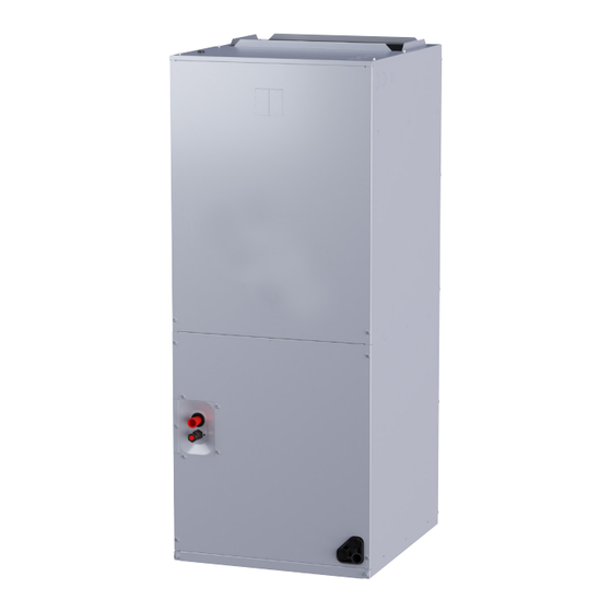
Multi-position air handler
Hide thumbs
Also See for Comfort-Aire Century SE Series:
- Instruction manual (12 pages) ,
- Instruction manual (28 pages) ,
- Instruction manual (24 pages)
Table of Contents
Advertisement
Quick Links
INSTALLER'S GUIDE
CONDENSING UNITS
Multi-Position Air Handler
High Efficiency Air Handlers
2-5Tons
R410a
Instruction Manual
Thank you very much for purchasing our product.
Before using your unit, please read this manual carefully and keep it for future reference.
The figure shown in this manual is for reference only and may be slightly different from the actual product.
517.787.2100 • www.marsdelivers.com
SE Series
AMC**S1A
ECM
Advertisement
Table of Contents

Related Manuals for Mars Comfort-Aire Century SE Series


Summary of Contents for Mars Comfort-Aire Century SE Series
- Page 1 INSTALLER’S GUIDE SE Series CONDENSING UNITS Multi-Position Air Handler High Efficiency Air Handlers 2-5Tons AMC**S1A R410a Instruction Manual Thank you very much for purchasing our product. Before using your unit, please read this manual carefully and keep it for future reference. The figure shown in this manual is for reference only and may be slightly different from the actual product.
- Page 2 AMC**S1A - Instruction Manual Multi-Position Air Handler-ECM RECOGNIZE THIS SYMBOL AS AN INDICATION OF IMPORTANT SAFETY INFORMATION WARNING These instructions are intended as an aid to qualified licensed service personnel for proper installation, adjustment and operation of this unit. Read these instructions thoroughly before attempting installation or operation. Failure to follow these instructions may result in improper installation, adjustment, service or maintenance possibly resulting in fire, electrical shock, property damage, personal injury or death.
-
Page 3: Table Of Contents
Multi-Position Air Handler-ECM AMC**S1A - Instruction Manual CONTENTS 1 SAFETY 2 GENERAL Unit Dimensions 3 APPLICATIONS Vertical Upflow Vertical Downflow Horizontal Installation In An Unconditioned Space 4 ELECTRICAL WIRING Power Wiring Control Wiring Grounding Electrical Data Heat Kit Data 5 AIRFLOW PERFORMANCE 6 DUCTWORK 7 7 REFRIGERANT CONNECTIONS Condensate Drain Tubing... -
Page 4: Safety
AMC**S1A - Instruction Manual Multi-Position Air Handler-ECM This document is customer property and should remain WARNING with this unit. These instructions do not cover all the different variations The unit must be permanently grounded. Failure systems nor does it provide for every possible to do so can result in electrical shock causing contingency to be met in connection with installation. -
Page 5: General
Multi-Position Air Handler-ECM AMC**S1A - Instruction Manual 2 GENERAL CAUTION The unit can be positioned for bottom return air in the Make sure the blower upflow position, left and right return in the horizontal motor support is tight position, top return in downflow position. (3-motor mount bolts) , then check to This Air Handler provides the flexibility for installation in... - Page 6 AMC**S1A - Instruction Manual Multi-Position Air Handler-ECM When the unit is installed in a hot and humid place, If the humidity inside the installation space might exceed 86°F and RH 80%, it is recommended to insulate the cabinet exterior. Use glass wool or polyethylene foam as insulation so that the thickness is more than 2 in. and fits inside the installation space opening.
-
Page 7: Unit Dimensions
Multi-Position Air Handler-ECM AMC**S1A - Instruction Manual 2.1 Unit Dimensions NOTE: 25” CLEARANCE IS REQUIRED IN THE FRONT OF THE UNIT FOR FILTER AND COIL MAINTENANCE. ELECTRICAL CONNECTIONS MAY EXIT TOP OR EITHER SIDE SUPPLY AIR FLANGES ARE PROVIDED FOR FIELD INSTALLATION HIGH VOLTAGE CONNECTION 7/8”, 1-3/8”, 1-3/4”... -
Page 8: Applications
AMC**S1A - Instruction Manual Multi-Position Air Handler-ECM 3 APPLICATIONS Replace breaker by inserting breaker mounting tab opposite white pull tab in opening, hook mounting tab over edge in opening. 3.1 Vertical Upflow With a screwdriver or pencil, pull the blue tab with hole away from breaker while setting that side of Upflow is default factory configuration. - Page 9 Multi-Position Air Handler-ECM AMC**S1A - Instruction Manual ENSURE THE RETAINING CHANNEL IS FULLY ENGAGED WITH THE COIL RAIL. DETAIL A RAILS AIRFLOW RAILS Fig.3-2 VERTICAL DOWNFLOW & HORIZONTAL LEFT APPLICATIONS (lower front service panel removed “view”.) STRAPS REAR WATER CATCHER TOP AIR STOP HORIZONTAL ADAPTER KIT VAPOR LINE CONNECTION...
-
Page 10: Installation In An Unconditioned Space
AMC**S1A - Instruction Manual Multi-Position Air Handler-ECM CAUTION Power wiring may be connected to either the right, left side or top. Three 7/8", 1-3/8", 1-3/4" dia. concentric knockouts are provided for connection of Horizontal units must be configured for right power wiring to unit. -
Page 11: Electrical Data
Multi-Position Air Handler-ECM AMC**S1A - Instruction Manual 4.4 Electrical Data CIRCUIT MAXIMUM CIRCUIT MODEL VOLTAGE SPEEDS HERTZ AMPS. PROTECTOR 208/230 15(A) 208/230 15(A) 60/61 208/230 15(A) 4.5 Heat Kit Data Max. Fuse or Min. Circuit Heater Kit Electric Breaker Minimum Heating Blower Speed Ampacity Handler Model... -
Page 12: Airflow Performance
AMC**S1A - Instruction Manual Multi-Position Air Handler-ECM 5. AIRFLOW PERFORMANCE Airflow performance data is based on cooling performance with a coil and no filter in place. Select performance table for appropriate unit size. External static applied to unit allows operation within the minimum and maximum limits shown in table below for both cooling and electric heat operation. - Page 13 Multi-Position Air Handler-ECM AMC**S1A - Instruction Manual CFM Wet Coil without filter and Electric Heat Outdoor Motor Unit External Static Pressure-Inches W.C.[kPa] Handler Speed Size(Tons) Model 0[0] 0.1[.025] 0.2[.050] 0.3[.075] 0.4[0.100] 0.5[0.125] 0.6[0.150] 0.7[0.175] 0.8[0.200] SCFM 1344 1284 1226 1151 1076 Power/W Current/A...
-
Page 14: Ductwork
AMC**S1A - Instruction Manual Multi-Position Air Handler-ECM Heat pump systems require a specified airflow for electric heat operating. Each ton of cooling requires between 350 and 450 cubic feet of air per minute (CFM), or 400 CFM nominally. Duct design and construction should be carefully done. System performance can be lowered dramatically through bad planning or workmanship. -
Page 15: Condensate Drain Tubing
Multi-Position Air Handler-ECM AMC**S1A - Instruction Manual 7.1 Condensate Drain Tubing Test condensate drain pan and drain line after installation is complete. Pour water into drain pan, enough to fill drain trap Consult local codes for specific requirements. and line. Check to make sure drain pan is draining completely, no leaks are found in drain line fittings, and water CONDENSATE DRAIN TRAP is draining from the termination of the primary drain line. -
Page 16: Filter Installation Dimensions
AMC**S1A - Instruction Manual Multi-Position Air Handler-ECM 9. FILTER INSTALLATION DIMENSIONS FILTER RAILS FILTER COVER MANUAL BOLT NOTE: Air filter is optional part, isn't factory-installed. Fig.9-1 EXTERNAL FILTER BASE DIMENSIONAL DATA Return width Return length FILTER SIZE "H" IN [mm] "W"... -
Page 17: Wiring Diagram
Multi-Position Air Handler-ECM AMC**S1A - Instruction Manual 10. WIRING DIAGRAM 10.1 For 24/36/60 Model THERMOSTAT 24RC W1/B Y1 Comp G Fan INDOOR UNIT OUTDOOR UNIT Fig.10-1 CONTROL WIRING FOR AC SYSTEMS THERMOSTAT W1/B 24RC Y1 Comp G Fan INDOOR UNIT OUTDOOR UNIT Fig.10-2 CONTROL WIRING FOR HP SYSTEMS... - Page 18 AMC**S1A - Instruction Manual Multi-Position Air Handler-ECM HIGH VOLTAGE! DISCONNECT ALL POWER BEFORE SERVICING OR INSTALLING THIS UNIT. MULTIPLE POWER SOURCES MAY BE PRESENT. FAILURE TO DO SO MAY CAUSE PROPERTY DAMAGE, PERSONAL INJURY OR DEATH. CAUTION: SCHEMATIC DIAGRAM NOT SUITABLE FOR USE ON SYSTEMS EXCEEDING 150V TO GROUND SEE RATING PLATE FOR VOLTS&HERTZ ATTENTION: FIELD POWER WIRING...
-
Page 19: For 61 Model
Multi-Position Air Handler-ECM AMC**S1A - Instruction Manual 10.2 For 61 Model Support 1H and 1C thermostat Y E L LO W R E D B R O W N G R E E N P U R PL E H/DH G R A Y THERMOSTAT B L U E... - Page 20 AMC**S1A - Instruction Manual Multi-Position Air Handler-ECM HIGH VOLTAGE! DISCONNECT ALL POWER BEFORE SERVICING OR INSTALLING THIS UNIT. MULTIPLE POWER SOURCES MAY BE PRESENT. FAILURE TO DO SO MAY CAUSE PROPERTY DAMAGE, PERSONAL INJURY OR DEATH. DETAILED REFERENCE SCHEMATIC DIAGRAM CAUTION: MANUAL INSTRUCTIONS NOT SUITABLE FOR USE ON SYSTEMS EXCEEDING 150V TO GROUND.
- Page 21 Multi-Position Air Handler-ECM AMC**S1A - Instruction Manual HEATER KIT PLUG HEATER KIT PLUG HEATER KIT PLUG HEATER KIT PLUG Wiring is subject to change. Always refer to the wiring diagram on the unit for the most up-to-date wiring.
- Page 22 AMC**S1A - Instruction Manual Multi-Position Air Handler-ECM 11. PISTON/TXV INSTALLATION Table 11-3.Superheat Charging Chart Charge the system by superheat when using a piston. Reference the outdoor unit installation guide to charge This coil comes with a factory installed piston metering the system by subcooling when using a TXV.
-
Page 23: Piston/Txv Installation
Multi-Position Air Handler-ECM AMC**S1A - Instruction Manual TXV Replacement Information for AMC61S1A NOTE: 1.The TXV replacement options noted in this sheet supersede those in the installation guide. Please reference this sheet for all refrigerant metering options. TXV-Replace Steps Step 1: Remove the screws and front coil panel. Step 2: Remove the rubber plugs from the liquid and vapor lines. - Page 24 SE SERIES LIMITED WARRANTY Congratulations on purchasing your new HVAC equipment. Your unit automatically qualifies for the warranty coverage listed below provided you meet the warranty conditions. APPLIES TO MODELS: RSA*, RSH*, AMP*, WMP*, WMX*, GFM*, MAA*, RHP*, RGP* YEAR 1 PRODUCT REPLACEMENT If the heat exchanger, evaporator coil (packaged systems only), condenser coil, or compressor fails within the first year (365 days) after the date of installation to the original consumer for the original installation, the original purchase cost of the unit will be reimbursed to the authorized Comfort-Aire/ Century distributor who has received prior authorization from Comfort-Aire/Century for the failure.
- Page 25 Page Intentionally Left Blank...
- Page 26 Page Intentionally Left Blank...
- Page 27 Page Intentionally Left Blank...
- Page 28 2/24...
Need help?
Do you have a question about the Comfort-Aire Century SE Series and is the answer not in the manual?
Questions and answers