
Summary of Contents for Chint Power CPS ESSR-05KL1
- Page 1 User Manual for CPS ESSR-05/10/15/20KL1 Energy Storage Battery Unit Shanghai Chint Power Systems Co., Ltd. Version 1.2 Oct., 2023...
-
Page 2: Table Of Contents
Table of Contents Table of Contents Introduction ..................4 Safety Instructions ................ 5 Explanation of safety symbols in the manual ......5 Interpretation of product markings ..........6 Precautions ................. 7 Product Introduction ..............9 Introduction to residential energy storage battery unit ....9 Model marking ................ - Page 3 Table of Contents Black start process ............38 Shutdown process ..............38 Storage and Recharging ............. 39 Battery storage requirements ............ 39 Recharging cycle and requirements ......... 40 Recharging operation ..............41 Battery power-on and commissioning steps ......42 Maintenance and Replacement ..........43 Maintenance precautions ............
-
Page 4: Introduction
Any reproduction, disclosure or copy in whole or in part is forbidden without prior written authorization. Chint Power reserves the right to modify and update this manual without prior written authorization. CHINT doesn’t accept any responsibilities whatsoever for potential errors or possible lack of information in this document. -
Page 5: Safety Instructions
Read this manual carefully before installing and operating the energy storage battery. If the equipment is not properly installed and used in accordance with the contents of this manual, resulting in damage to the equipment, Chint Power has the right to refuse warranty claims. -
Page 6: Interpretation Of Product Markings
Safety Instructions Interpretation of product markings DANGER! Electric Shock! There is a high voltage inside the machine body, so the instructions in the User Manual must be followed for operation of this product. Keep away from fire source! There is a lithium-ion battery in the equipment, which need to be stored or used away from fire sources. -
Page 7: Precautions
Safety Instructions Precautions WARNING! When installing, operating and maintaining the equipment, read this manual first and follow all safety precautions marked on the equipment and in the manual. DANGER! There is voltage in the equipment, and non-standard operation may cause electric shock or fire, resulting in death, serious injury or serious property loss. - Page 8 Safety Instructions NOTICE! During transportation, transfer, installation, wiring and maintenance, the requirements of laws, regulations and relevant standards of the country and region where the equipment is located must be met. The materials prepared by the user and the tools required during the ...
-
Page 9: Product Introduction
Fig 2-1: Typical Application of Energy Storage Battery Unit Model marking The model of CPS ESSR L1 series energy storage battery unit is CPS ESSR-05 (10/15/20) KL1. The following is an example of the meaning of CPS ESSR-05KL1. 9 / 53... -
Page 10: Instruction Of Energy Storage Capacity
Product Introduction Figure 2-1: Model of Energy Storage Battery Unit Name Meaning Company name CPS: Chint Power Systems Product type Residential energy storage system Energy level 05K: energy level of 5.12kWh Design code L1: product number of low voltages (LV) series... - Page 11 Product Introduction Figure 2-3 Energy Storage extension Instruction 11 / 53...
-
Page 12: Dimension And Appearance
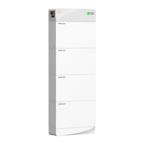
Product Introduction Dimension and appearance Introduction to overall appearance of energy storage battery unit Figure 2-4 Dimensions of Energy Storage Battery Unit Figure 2-5 Product Appearance 12 / 53... - Page 13 Product Introduction Name Function On/Off button Indicating startup/shutdown and operation state Power control module Controlling battery operation and inverter communication LED indicator Indicating SOC of the battery of the product Battery extension Battery extension unit module Explosion-proof valve Releasing battery pack pressure Base Carrying battery extension module Circuit breaker...
- Page 14 Product Introduction Figure 2-7 Appearance of Power control module Name Function Negative terminal of battery Negative terminal of battery output output Positive terminal of battery Positive terminal of battery output output Extension communication port Extension communication OUT Inverter communication port Inverter communication/extension communication IN Grounding terminal...
- Page 15 Product Introduction Figure 2-8 Dimensions of battery extension module Figure 2-9 Appearance of battery extension module Name Function Explosion-proof valve Pressure relief to prevent explosion Power plug-in female terminal Power and communication terminal Power plug-in male terminal Power and communication terminal Positioning area Positioning and fixing hole Handle...
-
Page 16: Led Display Instruction
Product Introduction Base module Figure 2-11 Appearance and Composition of Base Module Name Function Power plug-in male terminal Power and communication terminal Handle Handle and positioning Table 2-5 Main Components of Base Module LED display instruction Figure 2-12 Power-on Button and Indicator 16 / 53... - Page 17 Product Introduction Description Indicator Meaning Power on/off the battery unit ON/OFF button In the standby state, the operation state indicator flashes 1 time (on for 0.25s and off for 3.75s); In the charging process (charging current is greater ...
-
Page 18: Product Protection Function
Product Introduction Product protection function Short circuit protection Overcharge protection Over-discharge protection Over current protection Temperature protection Balance between cells Power module temperature monitoring Ambient temperature monitoring Cell temperature monitoring 18 / 53... -
Page 19: Installation
Installation Installation Inspection before installation Before installation, check whether the following items are contained in the packing box of each battery extension module and whether there is any damage. The delivery list of each battery extension module is as follows: Figure 3-1 delivery list of each battery extension module Accessory Name Qty. - Page 20 Installation Figure 3-2 delivery list of power control module Accessory Name Qty. Purpose Control battery operation and PCS Power control module communication Base Install battery extension module Wall bracket Support the whole battery unit Include packing list, warranty card Document bag and quick guide M12x100 expansion screw Fasten wall bracket...
-
Page 21: Installation Tools
Installation Installation tools Type Tools and Instruments Impact drill (Drill bit Ф8, Ф16m) Torque socket wrench Multimeter Marker Level ruler Steel tape Installation Diagonal pliers Rubber hammer Torque screwdriver Wire Crimpers (Type: PV- CZM- Wire stripper 22100/19100) Personal protection Safety gloves Safety shoes Protective glasses Table 3-3 Preparation of Installation Tools... -
Page 22: Installation Torques
Installation Installation torques Name Purpose Torque value M4 torque Tighten M4x14 combination screw and 1.2 N.m screwdriver M4x10 countersunk head screw M6 Torque Tighten Ф8x40 tapping screw and M6x14 5 N.m screwdriver combination screw #19 socket 40-45N.m Tighten M12x100 expansion screw wrench Table 3-4 Installation Torques Installation requirements... -
Page 23: Installation Method
Installation Installation method Before installing the battery unit, confirm whether the installed supporting structure can bear the weight of the battery unit, check whether the ground is level, and install the energy storage battery unit according to the following instructions: Vertical installation only;... -
Page 24: Installation Space
Installation Installation space The distance between the energy storage battery unit and the surrounding objects shall meet the following conditions: Figure 3-6 Dimensional Requirements for Floor Installation Figure 3-7 Dimensional Requirements for Wall-bracket Installation NOTICE! The distance between two parallel energy storage battery units must be ≥152.4MM(6IN), and good ventilation shall be ensured. -
Page 25: Installation Methods
Installation Installation methods Floor installation Place base on a level floor and keep within15 mm from wall surface. Align referrence line of positioning template with top line of base and then position the template onto the wall. Drill correct number of holes according to hole positions on the template, and knock plastic pipes of Ф8x40 tapping screws into the wall. - Page 26 Installation Two people jointly lift the battery extension module, align the battery extension module interface with the base and place it on the base. Figure 3-9 Position battery extension module on of base Lock screws into screw holes on both sides of the battery extension module, to ensure extension module is securely installed on the base;...
- Page 27 Installation Fasten power control module onto the battery extension module. Tools: M4x14 combination screw and M4 torque screwdriver Figure 3-11 Installation of Power control module NOTICE! When installing a battery extension module, screws must be installed on its left and right sides at first, the wall anchors must be locked on the wall with tapping screws, and then the next battery extension module can be installed.
-
Page 28: Wall-Bracket Installation
Installation Insert dust plugs into all the screw holes as showed, repeat this operation on the oppsite side till all the scew holes are plugged up. Figure 3-12 Insert dust plugs Wall-bracket Installation Make sure the installation position is level with a level ruler at first, and then mark the hole positions on the structure wall according to the dimensions of the wall bracket. - Page 29 Installation Figure 3-13 Mounting Hole Positions of Wall Bracket Secure the base to the wall bracket. Tools: M6x14 cross outer hexagon triple combination screw and M6 torque screwdriver. Figure 3-13 Fixing of Base to Wall Bracket 29 / 53...
- Page 30 Installation Finish all the subsequent steps by referring to the procedures of floor installation. Figure 3-14 Installation of Power control module CAUTION! The battery extension module weighs about 46 kg (≈100 lbs). Check the wall bracket again before hanging the battery unit to ensure that the wall bracket is firmly fixed on the support structure and locked with the base.
-
Page 31: Electrical Connection
Electrical Connection Electrical Connection CAUTION! Cable connections must comply with national electrical standards and all other applicable codes or legal standards. Cable specification Cross-sectional O.D. (mm) Name Type Area (mm DC cable Silicon wire, 600V, 4 AWG 8~10 GND cable 10 AWG, yellow-green wire 5.26 COM cable... -
Page 32: Wiring Instructions
Electrical Connection Name Function DC output negative quick-plug Connect negative power cable terminal DC output positive quick-plug Connect positive power cable terminal Multi-cluster extension Communicate between battery extension communication port modules Communication interface Communicate with inverter Grounding terminal Connect to external Grounding point Table 4-3 External Wiring Ports of Energy Storage Battery Unit Wiring instructions NOTICE! -
Page 33: Diagram Of System Structure
Electrical Connection Diagram of system structure Figure 4-2 Parallel Structure of Multiple Energy Storage Battery Units IMPORTANT! The length of DC input line and signal line between energy storage unit and inverter shall be ≤10m. Grounding cable connection DANGER! Confirm that the protective grounding cable is reliably connected. Disconnection or looseness may cause electric shock. -
Page 34: Communication Line Connection And Power Line Connection
Electrical Connection IMPORTANT! After installing the grounding cable, apply silicone adhesive or paint on the outside of the grounding terminal for protection. Communication line connection and Power line connection NOTICE! When arranging the signal cable, make sure to separate the routing of the signal cable from that of the power cable, and avoid large interference sources during routing, so as not to affect the communication due to signal interference. - Page 35 Electrical Connection Figure 4-5 communication cable connection According to actual demands of DC wiring terminal of the inverter, crimp OT terminal on power output line, and then fix the OT terminal to the DC side of the inverter with a screwdriver; or crimp DC quick-plug connectors and then insert them into DC quick-plug connector of inverter.
- Page 36 Electrical Connection Figure 4-7 Unplugging Cable Connector 36 / 53...
-
Page 37: Trial Operation
Trial Operation Trial Operation WARNING! Before trial operation, please follow the following guidelines to eliminate hidden dangers and ensure safety. Installation check Perform the following checks with reference to Section 3.5 Installation methods: Confirm that the support structure is firm and reliable. ... -
Page 38: Startup Process
Trial Operation Startup process Before trial operation, the above inspection must be completed to confirm that there is no error, and then the inverter shall be put into trial operation according to the following steps. General startup process Close DC Breaker (if any) configured between inverter and battery unit. Close the circuit breaker of power control module. -
Page 39: Storage And Recharging
Storage and Recharging Storage and Recharging Battery storage requirements During storage, the battery shall be placed correctly according to the identification of the packing box, and shall not be placed upside down or sideways. When the battery packing boxes are stacked, the stacking requirements on the outer packaging shall be met. -
Page 40: Recharging Cycle And Requirements
Storage and Recharging Recharging cycle and requirements In principle, it is not recommended to store the battery for a long time. Long-term deep discharge will cause battery damage, so it shall be used in time. Stored batteries shall be recharged according to the following temperature and cycle requirements. Temperature Actual storage Recharging... -
Page 41: Recharging Operation
Storage and Recharging NOTICE! Long-term storage of lithium batteries will cause capacity loss. After lithium batteries are stored at the recommended storage temperature for 6 months, the irreversible capacity loss is generally 3%~8%. If the customer carries out the discharge test and acceptance according to the specification, there is a risk that the battery whose storage capacity is less than 100% of the rated capacity will fail the test. -
Page 42: Battery Power-On And Commissioning Steps
Storage and Recharging Battery power-on and commissioning steps NOTICE! The charging process must be monitored by someone on site to prevent abnormal phenomena. If abnormalities such as bulging and smoking occur during charging, stop charging immediately and scrap the battery directly. The recharging operation must be carried out by professionals with ... -
Page 43: Maintenance And Replacement
Maintenance and Replacement Maintenance and Replacement WARNING! Before starting product maintenance, it is necessary to stop running the inverter and disconnect the AC circuit breaker connected to the power grid and the PV input connection on the DC side. During the operation of the energy storage battery unit, if only the circuit ... -
Page 44: Maintenance Precautions
Maintenance and Replacement Maintenance precautions You can use ladders to remove power control module or battery expansion unit if it’s necessary, as shown below. Fig. 7-1 Remove power control module or battery expansion unit. Please follow the following precautions if you need to use ladders to remove power control module or battery expansion unit. -
Page 45: Maintenance Items And Cycle
Maintenance and Replacement Maintenance items and cycle To ensure the long-term good operation of the energy storage battery unit, it is recommended to carry out routine maintenance according to the table below. Inspection Inspection Method Maintenance Cycle Contents System Regularly check whether the cooling fins Once half a year to cleaning are covered with dust and dirt. -
Page 46: Fault List
Maintenance and Replacement Fault List Troubleshooting of LED indicator LED Lamp Fault Status Troubleshooting 1. Turn the circuit breaker to the "OFF" position All lamps are out 2. Click the ON button and observe the indicator status The operation state lamp is off or See Table 7-3 for troubleshooting the alarm lamp is on Table 7-2 LED Indicator Fault... - Page 47 Maintenance and Replacement After confirming that communication line well connected, it is still unable to communicate, the user shall contact installation personnel maintenance and troubleshooting. 1. The user shall stop charging or discharging, and the battery will become normal after standing; 2.
- Page 48 Maintenance and Replacement Code Fault Type Failure Causes Circuit breaker Flash 1 Tripped level 3 overcurrent, relay sticking disconnection Voltage difference The difference between the highest and lowest Flash 2 excessive battery voltage exceeds the set threshold There is a module dropout or the total pressure collected at both ends of the battery and the Flash 3 Battery failure...
-
Page 49: Technical Data
Technical Data Technical Data ESSR- ESSR- ESSR- ESSR- Parameters 05KL1 10KL1 15KL1 20KL1 Voltage Voltage Level (V) LV 44.8~57.6 C-Rate C-Rate & Power Charge/Discharge Power(kW) Max Continue Current(A) DOD (%) 100% Battery System Energy Rated Capacity 5.12 10.24 15.36 20.48 (kWh) EOL (%) Life... - Page 50 Technical Data IEC 62619,IEC 63056,IEC 62040-1,IEC/UL Authentication 60730-1 annex H,CE EMC, EN 61000-6-1/- Authentication level 3,VDE 2510-50,UKCA,UN38.3 Charge:0~50 Working Temperature Temperature (℃) Discharge:-10~50 Altitude ≤3000 Others Humidity Up to 95% RH Heating Optional Black Start Mode Sleep Mode Pack Fire Control Optional Master/Slave Auto...
-
Page 51: Quality Assurance
"Instructions", "Notes", "Warnings" and "Dangers" in this manual do not represent all safety matters to be observed, but only serve as a supplement to all safety precautions. Chint Power does not assume any responsibility due to violating the requirements for general safety operation or violating the design, manufacturing and equipment safety operation standards. -
Page 52: Quality Terms
Quality Assurance product documentation. Damage to the hardware or data of the device due to negligence, improper operation or intentional damage by the customer. System damages caused by third parties or customers, including handling and installation that do not meet the requirements of this manual, as well as damages caused by adjustment, alteration or removal of identification signs that do not meet the requirements of this manual. - Page 53 Contact information Shanghai Chint Power Systems Co., Ltd. Headquarters: Building 4, No. 3255, Sixian Road, Songjiang District, Shanghai, China Switchboard: +86-21-3779-1222 Fax: +86-21-3779-1222-866003 Website: www.chintpower.com Service hotline: +86-21-3779-1222-866300 E-mail: service.cps@chint.com 53 / 53...
Need help?
Do you have a question about the CPS ESSR-05KL1 and is the answer not in the manual?
Questions and answers