Table of Contents
Troubleshooting

Related Manuals for BZ-TECH Voyager 1450g Series

Summary of Contents for BZ-TECH Voyager 1450g Series
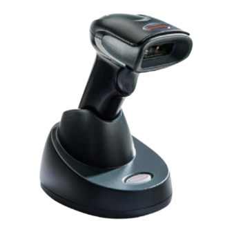
- Page 1 Leitor Voyager 1452g O Leitor Voyager 1452g 1D possui uma base Bluetooth dispensa o uso de cabo ou estar próximo ao computador para fazer leitura, aumentando assim a produtividade, praticidade e o manejo de seu leitor. www.bztech.com.br...
- Page 2 Voyager™ 1450g/1452g/1450g2DHR Series Area-Imaging Scanner User’s Guide...
- Page 3 Disclaimer Honeywell International Inc. (“HII”) reserves the right to make changes in specifications and other information contained in this document without prior notice, and the reader should in all cases consult HII to determine whether any such changes have been made.
-
Page 4: Table Of Contents
Table of Contents Customer Support Technical Assistance ......................ix Product Service and Repair ....................ix Limited Warranty ........................ix Send Feedback ........................ix Chapter 1 - Getting Started About This Manual .......................1-1 Unpacking Your Device .......................1-1 Connecting the Device ......................1-1 Connecting with USB .....................1-1 Connecting with Keyboard Wedge.................1-3 Connecting with RS232 Serial Port................1-4... - Page 5 Control Character Output ....................2-17 Keyboard Modifiers......................2-17 RS232 Modifiers ........................ 2-18 RS232 Baud Rate......................2-18 RS232 Word Length: Data Bits, Stop Bits, and Parity ..........2-19 RS232 Receiver Time-Out................... 2-20 RS232 Handshaking....................2-20 RS232 Timeout......................2-21 XON/XOFF ........................2-21 ACK/NAK ........................
- Page 6 Scanner Address ......................... 3-9 Base or Access Point Address .................... 3-9 Scanner Modes ........................3-9 Charge Only Mode......................3-9 Linked Modes ........................ 3-9 Unlinking the Scanner ....................... 3-10 Override Locked Scanner .................... 3-10 Out-of-Range Alarm ......................3-10 Alarm Sound Type ....................... 3-11 Scanner Power Time-Out Timer..................
- Page 7 Good Read and Error Indicators..................4-2 Beeper – Good Read..................... 4-2 Beeper Volume – Good Read..................4-2 Beeper Pitch – Good Read.................... 4-2 Beeper Pitch – Error ...................... 4-3 Beeper Duration – Good Read ..................4-3 LED – Good Read ......................4-3 Number of Beeps –...
- Page 8 Chapter 5 - Data Editing Prefix/Suffix Overview ......................5-1 To Add a Prefix or Suffix:....................5-1 To Clear One or All Prefixes or Suffixes ................ 5-2 To Add a Carriage Return Suffix to All Symbologies ............. 5-2 Prefix Selections........................5-2 Suffix Selections ........................
- Page 9 GS1-128 ..........................7-17 UPC-A ..........................7-17 UPC-A/EAN-13 with Extended Coupon Code ..............7-19 Coupon GS1 DataBar Output.................... 7-20 UPC-E0 ..........................7-20 UPC-E1 ..........................7-22 EAN/JAN-13 ........................7-23 Convert UPC-A to EAN-13 ..................7-23 ISBN Translate ......................7-25 EAN/JAN-8 ........................7-25 MSI ............................
- Page 10 Chapter 9 - Serial Programming Commands Conventions......................... 9-1 Menu Command Syntax ...................... 9-1 Query Commands ....................... 9-1 Responses........................9-2 Trigger Commands......................9-3 Resetting the Custom Defaults.................... 9-3 Menu Commands ........................ 9-3 Chapter 10 - Product Specifications Voyager 1450g Scanner Product Specifications ............... 10-1 Voyager 1450g2DHR Scanner Product Specifications .............
- Page 11 Programming Chart viii...
-
Page 12: Customer Support
Customer Support Technical Assistance To search our knowledge base for a solution or to log in to the Technical Support portal and report a problem, go to www.hsmcontactsupport.com. For our latest contact information, see www.honeywellaidc.com/locations. Product Service and Repair Honeywell International Inc. provides service for all of its products through service centers throughout the world. To obtain warranty or non-warranty service, please visit www.honeywellaidc.com and select Support >... -
Page 14: Chapter 1 - Getting Started
Getting Started About This Manual This User’s Guide provides installation and programming instructions for the Voyager™ 1450g corded area-imaging scanners and Voyager 1452g cordless area-imaging scanners. Product specifications, dimensions, warranty, and customer support infor- mation are also included. Note: The selections in this User’s Guide are dependent on the Voyager 145Xg model you have purchased. PDF and 2 dimensional bar codes can only be read by model 145Xg2D and cannot be read by model 145Xg1D. - Page 15 CCB01-010BT Base USB Connection: Note: The power supply must be ordered separately, if needed. 2. If you are connecting a CCB01-010BT Base, make sure the cables are secured in the wireways in the bottom of the cordless base and the base sits flat on a horizontal surface. 3.
-
Page 16: Connecting With Keyboard Wedge
Connecting with Keyboard Wedge A scanner or cordless base can be connected between the keyboard and PC as a “keyboard wedge,” where the scanner provides data output that is similar to keyboard entries. The following is an example of a keyboard wedge connection: 1. -
Page 17: Connecting With Rs232 Serial Port
Connecting with RS232 Serial Port 1. Turn off power to the terminal/computer. 2. Connect the appropriate interface cable to the device. Note: For the scanner or cordless base to work properly, you must have the correct cable for your type of terminal/computer. Corded Voyager 1450g RS232 Serial Port Connection: CCB01-010BT Base... -
Page 18: Connecting With Rs485
Connecting with RS485 A scanner or cordless base can be connected for an IBM POS terminal interface. 1. Connect the appropriate interface cable to the device, then to the computer. Corded Voyager 1450g RS232 Serial Port Connection: CCB01-010BT Base RS485 Connection: 2. -
Page 19: Mounting A Ccb01-010Bt Charge Base
Mounting a CCB01-010BT Charge Base 2.36 in. 2.8 in. 59.84mm 72.1mm 3.35 in. 8x32 thread 85.09mm x .39 in. (10mm) deep Reading Techniques The scanner has a view finder that projects a bright red aiming beam that corresponds to the scanner’s horizontal field of view. The aiming beam should be centered over the bar code, but it can be positioned in any direction for a good read. -
Page 20: Setting Custom Defaults
Setting Custom Defaults You have the ability to create a set of menu commands as your own, custom defaults. To do so, scan the Set Custom Defaults bar code below before scanning the menu commands for your custom defaults. If a menu command requires scanning numeric codes from the back cover, then a Save code, that entire sequence will be saved to your custom defaults. - Page 21 1 - 8...
-
Page 22: Chapter 2 - Programming The Interface
Programming the Interface Introduction This chapter describes how to program your system for the desired interface. Programming the Interface - Plug and Play Plug and Play bar codes provide instant scanner set up for commonly used interfaces. Note: After you scan one of the codes, power cycle the host terminal to have the interface in effect. Keyboard Wedge If you want your system programmed for an IBM PC AT and compatibles keyboard wedge interface with a USA keyboard, scan the bar code below. -
Page 23: Rs485
RS485 Scan one of the following “Plug and Play” codes to program the scanner for an IBM POS terminal interface. Note: After scanning one of these codes, you must power cycle the cash register. IBM Port 5B Interface IBM Port 9B HHBCR-1 Interface IBM Port 17 Interface IBM Port 9B... -
Page 24: Usb Ibm Surepos
RS485 Packet Length If you are using Packet mode, you can specify the size of the data “packet” that is sent to the host. Scan the Packet Length bar code, then then the packet size (from 20 - 256) from the Programming Chart inside the back cover of this manual, then Save. -
Page 25: Usb Hid
USB HID Scan the following code to program the scanner for USB HID bar code scanners. USB HID Bar Code Scanner USB Serial Scan the following code to program the scanner to emulate a regular RS232-based COM Port. If you are using a Microsoft® Windows®... -
Page 26: Remote Mastermind™ For Usb
Remote MasterMind™ for USB When using a USB interface, you may wish to configure your scanner to communicate with Remote MasterMind Scanner Man- agement Software (ReM). Scan the ReM On bar code to communicate with ReM. To disable this capability, scan ReM Off. Default = ReM On. -
Page 27: Honeywell Bioptic Aux Port Configuration
Honeywell Bioptic Aux Port Configuration Scan the following Plug and Play code to program the scanner for a Honeywell bioptic scanner auxiliary port configuration. This bar code sets the baud rate to 38400 bps and the data format to 8 data bits, no parity, 1 stop bit. Honeywell Bioptic Settings ©... -
Page 28: Wincor Nixdorf Beetle™ Terminal Default Settings
Wincor Nixdorf Beetle™ Terminal Default Settings Scan the following Plug and Play code to program the scanner for a Wincor Nixdorf Beetle terminal. This bar code sets the baud rate to 115200 bps and the data format to 8 data bits, no parity, 1 stop bit. The following prefixes are programmed for each symbology: Symbology Prefix... -
Page 29: Keyboard Country Layout
Keyboard Country Layout If your interface is USB Keyboard or Keyboard Wedge, your keyboard layout default is a US keyboard. To change this layout, refer to the chart below for your keyboard country. Scan the appropriate bar code below to change the layout. By default, national character replacements are used for the following characters: #$@[\]^‘{|}~ See ISO 2022/ISO 646 Character Replacements... - Page 30 Keyboard Countries (Continued) Bulgaria (Latin) Canada (French legacy) Canada (French) Canada (Multilingual) Croatia Czech Czech (Programmers) Czech (QWERTY) Czech (QWERTZ) Denmark Dutch (Netherlands) 2 - 9...
- Page 31 Keyboard Countries (Continued) Estonia Faroese Finland France Gaelic Germany Greek Greek (220 Latin) Greek (220) Greek (319 Latin) Greek (319) 2 - 10...
- Page 32 Keyboard Countries (Continued) Greek (Latin) Greek (MS) Greek (Polytonic) Hebrew Hungarian (101 key) Hungary Iceland Irish Italian (142) Italy Japan ASCII 2 - 11...
- Page 33 Keyboard Countries (Continued) Kazakh Kyrgyz (Cyrillic) Latin America Latvia Latvia (QWERTY) Lithuania Lithuania (IBM) Macedonia Malta Mongolian (Cyrillic) Norway 2 - 12...
- Page 34 Keyboard Countries (Continued) Poland Polish (214) Polish (Programmers) Portugal Romania Russia Russian (MS) Russian (Typewriter) Serbia (Cyrillic) Serbia (Latin) 2 - 13...
- Page 35 Keyboard Countries (Continued) Slovakia Slovakia (QWERTY) Slovakia (QWERTZ) Slovenia Spain Spanish variation Sweden Switzerland (French) Switzerland (German) Tatar Turkey F 2 - 14...
-
Page 36: Keyboard Style
Keyboard Countries (Continued) Turkey Q Ukrainian United Kingdom United States (Dvorak) United States (Dvorak left) United Stated (Dvorak right) United States (International) Uzbek (Cyrillic) Keyboard Style This programs keyboard styles, such as Caps Lock and Shift Lock. If you have used Keyboard Conversion settings, they will override any of the following Keyboard Style settings. -
Page 37: Keyboard Conversion
Shift Lock is used when you normally have the Shift Lock key on (not common to U.S. keyboards). Shift Lock Automatic Caps Lock is used if you change the Caps Lock key on and off. The software tracks and reflects if you have Caps Lock on or off . -
Page 38: Control Character Output
Control Character Output This selection sends a text string instead of a control character. For example, when the control character for a carriage return is expected, the output would display [CR] instead of the ASCII code of 0D. Refer to ASCII Conversion Chart (Code Page 1252) on page A-3. -
Page 39: Rs232 Modifiers
Turbo Mode: The scanner sends characters to a terminal faster. If the terminal drops characters, do not use Turbo Mode. Default = Off. Turbo Mode On * Turbo Mode Off Numeric Keypad Mode: Sends numeric characters as if entered from a numeric keypad. Default = Off. Numeric Keypad Mode On * Numeric Keypad Mode Off Automatic Direct Connect Mode: This selection can be used if you have an IBM AT style terminal and the system is dropping... -
Page 40: Rs232 Word Length: Data Bits, Stop Bits, And Parity
1200 2400 4800 9600 19200 38400 57,600 * 115,200 RS232 Word Length: Data Bits, Stop Bits, and Parity Data Bits sets the word length at 7 or 8 bits of data per character. If an application requires only ASCII Hex characters 0 through 7F decimal (text, digits, and punctuation), select 7 data bits. -
Page 41: Rs232 Receiver Time-Out
7 Data, 1 Stop, Parity None 7 Data, 1 Stop, Parity Odd 7 Data, 2 Stop, Parity Even 7 Data, 2 Stop Parity None 7 Data, 2 Stop, Parity Odd 8 Data, 1 Stop, Parity Even * 8 Data, 1 Stop, Parity None 8 Data, 1 Stop, Parity Odd RS232 Receiver Time-Out The unit stays awake to receive data until the RS232 Receiver Time-Out expires. -
Page 42: Rs232 Timeout
Two-Direction Flow Control: The scanner asserts RTS when it is OK for the host to transmit. The host asserts CTS when it is OK for the device to transmit. Flow Control with Timeout: The scanner asserts RTS when it has data to send and waits for a delay (see RS232 Timeout on page 2-21) for CTS to be asserted by the host. -
Page 43: Ack/Nak
ACK/NAK After transmitting data, the scanner waits for an ACK character (hex 06) or a NAK character (hex 15) response from the host. If ACK is received, the communications cycle is completed and the scanner looks for more bar codes. If NAK is received, the last set of bar code data is retransmitted and the scanner waits for ACK/NAK again. -
Page 44: Scanner-Bioptic Ack/Nak Timeout
Scanner-Bioptic ACK/NAK Timeout This allows you to set the length (in milliseconds) for a timeout for a bioptic scanner’s ACK/NAK response. Scan the bar code below, then set the timeout (from 1-30,000 milliseconds) by scanning digits from the inside back cover, then scanning Save. - Page 45 2 - 24...
-
Page 46: Chapter 3 - Cordless System Operation
Cordless System Operation Note: This chapter applies only to cordless scanning systems. It does not apply to corded scanners. How the Cordless Charge Base/Access Point Works A cordless charge base or an Access Point provide the link between the cordless scanner and the host system. The base/ Access Point contains an interface assembly and an RF communication module. -
Page 47: Replacing A Linked Scanner
Scan the linking bar code on the top of the Access Point to establish a connection between the Access Point and the scanner. The scanner emits a short beep and flashes the green LED to confirm a connection with the Access Point. The Access Point’s Page button remains blue. -
Page 48: Programming The Scanner And Base Or Access Point
Programming the Scanner and Base or Access Point When using the scanner and charge base or Access Point together as a system, menu parameters and configuration settings are stored in the charge base or Access Point. Therefore, when programming any menu configuration settings, the scanner must be linked to the intended charge base or Access Point. -
Page 49: About The Battery
About the Battery There is a danger of explosion if the batteries are incorrectly replaced. Replace the batteries with only the same or equivalent type recommended by the manufacturer. Dispose of used batteries according to the recycle program for batteries as directed by the governing agency for the country where the batteries are to be discarded. Power is supplied to the cordless scanner by a rechargeable battery that is integrated in the scanner handle. -
Page 50: Beeper And Led Sequences And Meaning
Beeper and LED Sequences and Meaning The scanner contains LEDs on the rear of the unit that indicate linking status, decoding state, and battery condition. The base has LEDs on the top of the unit that indicate its power up, communication, and battery charge condition. The red LED = error; green LED = success of any type. -
Page 51: Reset Scanner
Base Power Communication Indicator Off Reset Scanner Scanning this bar code reboots the scanner and causes it to relink with the base or Access Point. Reset Scanner Scanning While in Base Cradle If you want to be able to scan bar codes while the scanner is in the base cradle, scan the Scanning in Cradle On bar code below. -
Page 52: Paging
Default = External or Interface Cable Power. Base Charge Off External or Interface Cable Power External Power Only Paging Paging Mode By default, the paging button on the base or Access Point pages the scanners associated with that base or Access Point. If you want the paging button on your base or Access Point to be disabled, scan the Paging Mode Off bar code, below. -
Page 53: Error Indicators
High (4200 Hz) Error Indicators Beeper Pitch - Base Error The CCB01-010BT base can be configured to beep at a particular pitch when an error occurs, such as transmission prob- lems to a host system. The beeper pitch codes modify the pitch (frequency) of the error tone the base emits when there is an error. -
Page 54: Scanner Address
Scanner Address Scan the bar code below to determine the address of the scanner you are using. Scanner Address Base or Access Point Address Scan the bar code below to determine the address of the base or Access Point you are using. Base Address Scanner Modes Your scanner is capable of working in single scanner mode, multiple scanner mode, or with Bluetooth devices other than the... -
Page 55: Unlinking The Scanner
Locked Link Mode - Single Scanner If you link a scanner to a base or an Access Point using the Locked Link Mode, other scanners are blocked from being linked if they are inadvertently placed into the base, or if the Access Point linking bar code is scanned. If you do place a different scanner into a base, it will charge the scanner, but the scanner will not be linked. -
Page 56: Alarm Sound Type
options for the scanner or the base and to set the alarm duration, scan the appropriate bar code below and then set the timeout duration (from 0-3000 seconds) by scanning digits on the Programming Chart inside the back cover, then scanning Save. Default = 0 sec (no alarm). -
Page 57: Flexible Power Management
If there are no trigger pulls during the timer interval, the scanner goes into power down mode. Whenever the trigger is enabled, the timer is reset. If the scanner is placed in the charge base cradle and the battery is in the process of being charged, the scanner will not go into power down mode. -
Page 58: Batch Mode
Scan one of the bar codes below to set the scanner’s power output to Full Power (100%), Medium Power (35%), Medium Low Power (5%), or Low Power (1%). Default = Full Power. * Full Power Medium Power Medium Low Power Low Power Batch Mode Note: Batch Mode is only supported by the Honeywell Charge and Communication Base (CCB) and Honeywell Access Point... -
Page 59: Batch Mode Beep
Inventory Batch Mode Persistent Batch Mode Batch Mode Beep When scanning in Inventory Batch Mode (page 3-14), the scanner beeps every time a bar code is scanned. When Batch Mode Beep is On, you will also hear a click when each bar code is sent to the host. If you do not want to hear these clicks, scan Batch Mode Beep Off. -
Page 60: Batch Mode Quantity
Batch Mode Quantity When in Batch Mode, you may wish to transmit the number of multiple bar codes scanned, rather than a single bar code multiple times. For example, if you scan three bar codes called XYZ with Batch Mode Quantity Off, when you transmit your data it will appear as XYZ three times. -
Page 61: Batch Mode Output Order
Batch Mode Output Order When batch data is transmitted, select whether you want that data sent as FIFO (first-in first-out), or LIFO (last-in first-out). Default = Batch Mode FIFO. * Batch Mode FIFO Batch Mode LIFO 3 - 16... -
Page 62: Total Records
Total Records If you wish to output the total number of bar codes scanned when in Batch Mode, scan Total Records. Total Records Delete Last Code If you want to delete the last bar code scanned when in Batch Mode, scan Delete Last Code. Delete Last Code Clear All Codes If you want to clear the scanner’s buffer of all data accumulated in Batch Mode, scan Clear All Codes. -
Page 63: Multiple Scanner Operation
Batch Mode Transmit Delay Medium (500 ms) Batch Mode Transmit Delay Long (1000 ms) Multiple Scanner Operation Note: Multiple Scanner Operation Mode allows you to link up to 7 scanners to one base or Access Point. You cannot join an 8th scanner until you unlink one of the 7 scanners or take a scanner out of range. -
Page 64: Application Work Groups
0004 0005 0006 0007 Reset You may also scan the Scanner Name bar code below and scan a number for the scanner name. For example, if you wanted to name the linked scanner “312,” you would scan the bar code below, scan the 3, 1, and 2 bar codes on the Programming Chart inside the back cover of this manual, then scan Save. -
Page 65: Application Work Group Selection
Application Work Group Selection This programming selection allows you to assign a scanner to a work group by scanning the bar code below. You may then program the settings (e.g., beeper volume, prefix/suffix, data formatter) that your application requires. Default = Group 0. * Group 0 Group 1 Group 2... -
Page 66: Resetting The Custom Defaults: All Application Work Groups
Resetting the Custom Defaults: All Application Work Groups If you want the custom default settings restored to all of the work groups, scan the Custom Product Default Settings bar code below. (If there are no custom defaults, it will reset the work groups to the factory defaults.) See "Setting Custom Defaults" on page 1-7 for further information about custom defaults. -
Page 67: Virtual Keyboard
Save Your personal computer, laptop, or tablet should now be paired with the scanner. Once the scanner battery is charged and you have paired it, you may begin scanning bar codes. Verify the scanner opera- tion by scanning a bar code from the Sample Symbols in the back of this manual. -
Page 68: Bluetooth Hid Keyboard Disconnect
Bluetooth HID Keyboard Disconnect If your scanner has been connected directly to an iPad, smart phone, or laptop using Bluetooth HID Keyboard Connect (page 3-21), you must disconnect it in order to once again communicate with the base or Access Point. Scan the Blue- tooth HID Keyboard Disconnect bar code to unlink the scanner from the currently linked host. -
Page 69: Auto Reconnect Mode
Auto Reconnect Mode Auto Reconnect controls whether or not the scanner automatically begins the relink process when a loss of connection is detected. When the Auto Reconnect On bar code is scanned, the scanner begins the relink process immediately, without user intervention. -
Page 70: Relink Time-Out
Scan the Maximum Link Attempts bar code, then scan the number of attempts for the setting (from 0-100) from the inside back cover. Scan Save to save the setting. Default = 0. Maximum Link Attempts Note: When Auto Reconnect Mode is On, setting Maximum Link Attempts to zero will cause the scanner to try to link until the Power Time-Out Timer setting (see page 3-11) expires. -
Page 71: Host Acknowledgment
Host Acknowledgment Some applications require that the host terminal (or server) validate incoming bar code data (database look-up) and provide acknowledgment to the scanner whether or not to proceed. In Host ACK Mode, the scanner waits for this acknowledgment after each scan. -
Page 72: Host Ack Timeout
Host ACK On/Off Host ACK On * Host ACK Off Host ACK Timeout You can set a timeout for the length of time the scanner waits for a valid escape command when using Host Acknowledg- ment Mode. Set the length (in seconds) for a timeout by scanning the following bar code, then setting the timeout (from 1- 90 seconds) by scanning digits from the Programming Chart, then scanning Save. - Page 73 3 - 28...
-
Page 74: Chapter 4 - Input/Output Settings
Input/Output Settings Power Up Beeper The scanner can be programmed to beep when it’s powered up. If you are using a cordless system, the base can also be pro- grammed to beep when it is powered up. Scan the Off bar code(s) if you don’t want a power up beep. Default = Power Up Beeper On - Scanner. -
Page 75: Good Read And Error Indicators
Trigger Click On Good Read and Error Indicators Beeper – Good Read The beeper may be programmed On or Off in response to a good read. Turning this option off, only turns off the beeper response to a good read indication. All error and menu beeps are still audible. Default = Beeper - Good Read On. Beeper - Good Read Off * Beeper - Good Read On Beeper Volume –... -
Page 76: Beeper Pitch - Error
* Medium (2400 Hz) High (4200 Hz) Beeper Pitch – Error The beeper pitch codes modify the pitch (frequency) of the sound the scanner emits when there is a bad read or error. Default = Razz. * Razz (250 Hz) Medium (3250 Hz) High (4200 Hz) Beeper Duration –... -
Page 77: Number Of Beeps - Good Read
Number of Beeps – Good Read The number of beeps of a good read can be programmed from 1 - 9. The same number of beeps will be applied to the beeper and LED in response to a good read. For example, if you program this option to have five beeps, there will be five beeps and five LED flashes in response to a good read. -
Page 78: Manual Trigger Mode
Manual Trigger Mode When in manual trigger mode, the scanner scans until a bar code is read, or until the trigger is released. Default = Manual Trig- ger-Normal. * Manual Trigger - Normal LED Illumination - Manual Trigger If you wish to set the illumination LED brightness, scan one of the bar codes below. This sets the LED illumination for the scanner when the trigger is pressed. -
Page 79: Presentation Mode
Presentation Mode Presentation Mode uses ambient light to detect bar codes. The LED dims until a bar code is presented to the scanner, then the LED brightens to read the code. If the light level in the room is not high enough, Presentation Mode may not work properly. Note: If you are using a cordless charge base in Presentation Mode, the battery will not charge unless the power supply is plugged into the base’s auxiliary power port. - Page 80 If a bar code is not touched by a predefined window, it will not be decoded or output by the scanner. If Presentation Center- ing is turned on by scanning Presentation Centering On, the scanner only reads codes that pass through the centering window you specify using the Top of Presentation Centering Window, Bottom of Presentation Centering Window, Left, and Right of Presentation Centering Window bar codes.
-
Page 81: In-Stand Sensor Mode
Bottom of Presentation Centering Window Left of Presentation Centering Window Right of Presentation Centering Window In-Stand Sensor Mode This feature senses when the scanner is removed from the stand and tells it to begin manual triggering. When Sensor On is enabled, the scanner defaults to Presentation Mode when it is in the stand, and to Manual Trigger Mode when it is removed from the stand. -
Page 82: Poor Quality Pdf Codes
Poor Quality PDF Codes This setting improves the scanner’s ability to read damaged or badly printed PDF codes by combining information from mul- tiple images. When Poor Quality PDF On is scanned, poor quality PDF code reading is improved, but the scanner’s snap- piness is decreased, making it less aggressive when reading good quality bar codes. -
Page 83: 2D Reread Delay
Scan the Hands Free Time-Out bar code, then scan the time-out duration (from 0-300,000 milliseconds) from the inside back cover, and Save. Default = 5,000 ms. Hands Free Time-Out Reread Delay This sets the time period before the scanner can read the same bar code a second time. Setting a reread delay protects against accidental rereads of the same bar code. -
Page 84: Character Activation Mode
Short (1000ms) Medium (2000ms) Long (3000ms) Extra Long (4000ms) Character Activation Mode You may use a character sent from the host to trigger the scanner to begin scanning. When the activation character is received, the scanner continues scanning until either the Character Activation Timeout (page 4-12), the deactivation character is received (see... -
Page 85: End Character Activation After Good Read
End Character Activation After Good Read After a bar code is successfully detected and read from the scanner, the aimer can be programmed either to remain on and scanning, or to turn off. When End Character Activation After Good Read is enabled, the aimer turns off and stops scanning after a good read. -
Page 86: Illumination Lights
Illumination Lights If you want the illumination lights on while reading a bar code, scan the Lights On bar code, below. However, if you want to turn just the lights off, scan the Lights Off bar code. Default = Lights On. Note: This setting does not affect the aimer light. -
Page 87: Centering
* Interlaced Centering Use Centering to narrow the scanner’s field of view to make sure that when the scanner is hand-held, it reads only those bar codes intended by the user. For instance, if multiple codes are placed closely together, centering will insure that only the desired codes are read. -
Page 88: No Read
* Centering Off Top of Centering Window Bottom of Centering Window Left of Centering Window Right of Centering Window No Read With No Read turned On, the scanner notifies you if a code cannot be read. If using an EZConfig-Scanning Tool Scan Data Window (see page 8-2), an “NR”... -
Page 89: Video Reverse
Video Reverse Video Reverse is used to allow the scanner to read bar codes that are inverted. The Video Reverse Off bar code below is an example of this type of bar code. Scan Video Reverse Only to read only inverted bar codes. Scan Video Reverse and Stan- dard Bar Codes to read both types of codes. - Page 90 * Upright Vertical, Bottom to Top Upside Down Vertical, Top to Bottom 4 - 17...
- Page 91 4 - 18...
-
Page 92: Chapter 5 - Data Editing
Data Editing Prefix/Suffix Overview When a bar code is scanned, additional information is sent to the host computer along with the bar code data. This group of bar code data and additional, user-defined data is called a “message string.” The selections in this section are used to build the user-defined data into the message string. -
Page 93: To Clear One Or All Prefixes Or Suffixes
Example: Add a Tab Suffix to All Symbologies Step 1. Scan Add Suffix. Step 2. Scan 9, 9 from the Programming Chart inside the back cover of this manual to apply this suffix to all symbologies. Step 3. Scan 0, 9 from the Programming Chart inside the back cover of this manual. -
Page 94: Function Code Transmit
Clear One Suffix Clear All Suffixes Function Code Transmit When this selection is enabled and function codes are contained within the scanned data, the scanner transmits the function code to the terminal. Charts of these function codes are provided in "ASCII Conversion Chart (Code Page 1252)" on page A-3 starting on page A-3. -
Page 95: Interfunction Delay
Next, scan the Character to Trigger Delay bar code, then the 2-digit hex value for a printable character to trigger the delay (see Lower ASCII Reference Table on page A-4). Delay Length Character to Trigger Delay To remove this delay, scan the Delay Length bar code, and set the number of delays to 0. Scan the Save bar code using Programming Chart inside the back cover of this manual. -
Page 96: Chapter 6 - Data Formatting
Data Formatting Data Format Editor Introduction You may use the Data Format Editor to change the scanner’s output. For example, you can use the Data Format Editor to insert characters at certain points in bar code data as it is scanned. The selections in the following pages are used only if you wish to alter the output. -
Page 97: Other Programming Selections
from the Programming Chart inside the back cover of this manual. (Note: 50 characters is entered as 0050. 9999 is a universal number, indicating all lengths.) Step 6. Editor Commands Refer to Data Format Editor Commands (page 6-3). Scan the symbols that represent the command you want to enter. Step 7. -
Page 98: Terminal Id Table
Terminal ID Table Terminal Model(s) Terminal ID PC keyboard (HID) Mac Keyboard PC Keyboard (Japanese) Serial (COM driver required) HID POS USB SurePOS Handheld USB SurePOS Tabletop Serial RS232 TTL RS232 True Keyboard PS2 compatibles Data Format Editor Commands Send Commands Send all characters F1 Include in the output message all of the characters from the input message, starting from current cursor position, followed by an insert character. -
Page 99: Move Commands
The data is output as: 1234567890 ABCDEFGHIJ <CR> Send all characters up to a particular character F3 Include in the output message all characters from the input message, starting with the character at the current cursor position and continuing to, but not including, the search character “ss,” followed by an insert character. The cursor is moved forward to the “ss”... -
Page 100: Search Commands
F5 Example: Move the cursor forward and send the data Move the cursor forward 3 characters, then send the rest of the bar code data from the bar code above. End with a carriage return. Command string: F503F10D F5 is the “Move the cursor forward a number of characters” command 03 is the number of characters to move the cursor F1 is the “Send all characters”... - Page 101 F8 Example: Send bar code data that starts after a particular character Search for the letter “D” in bar codes and send all the data that follows, including the “D.” Using the bar code above: Command string: F844F10D F8 is the “Search forward for a character” command 44 is the hex value for “D”...
-
Page 102: Miscellaneous Commands
Miscellaneous Commands Suppress characters FB Suppress all occurrences of up to 15 different characters, starting at the current cursor position, as the cursor is advanced by other commands. When the FC command is encountered, the suppress function is terminated. The cursor is not moved by the FB command. - Page 103 The data is output as: 1234 5678 <CR> Stop replacing characters E5 Terminates character replacement. Syntax = E5. Compare characters FE Compare the character in the current cursor position to the character “xx.” If characters are equal, move the cursor forward one position.
-
Page 104: Data Formatter
Insert a delay EF Inserts a delay of up to 49,995 milliseconds (in multiples of 5), starting from the current cursor position. Syntax = EFnnnn where nnnn stands for the delay in 5ms increments, up to 9999. This command can only be used with keyboard emulation. - Page 105 Data Format 3 6 - 10...
-
Page 106: All Symbologies
Symbologies This programming section contains the following menu selections. Refer to Chapter 9 for settings and defaults. • All Symbologies • Interleaved 2 of 5 • Aztec Code • Korea Post • China Post (Hong Kong 2 of 5) • Matrix 2 of 5 •... -
Page 107: Codabar
EXAMPLE: Decode only those bar codes with a count of 9-20 characters. Min. length = 09Max. length = 20 EXAMPLE: Decode only those bar codes with a count of 15 characters. Min. length = 15Max. length = 15 For a value other than the minimum and maximum message length defaults, scan the bar codes included in the explanation of the symbology, then scan the digit value of the message length and Save bar codes on the Programming Chart inside the back... -
Page 108: Codabar Concatenation
When Check Character is set to Validate, but Don’t Transmit, the unit will only read Codabar bar codes printed with a check character, but will not transmit the check character with the scanned data. * No Check Character Validate Modulo 16, but Don’t Transmit Validate Modulo 16 and Transmit... -
Page 109: Code 39
Maximum Message Length Code 39 < Default All Code 39 Settings > Code 39 On/Off * On Code 39 Start/Stop Characters Start/Stop characters identify the leading and trailing ends of the bar code. You may either transmit, or not transmit Start/ Stop characters. -
Page 110: Code 32 Pharmaceutical (Paraf)
Validate, but Don’t Transmit Validate and Transmit Code 39 Message Length Scan the bar codes below to change the message length. Refer to Message Length Description (page 7-1) for additional information. Minimum and Maximum lengths = 0-48. Minimum Default = 0, Maximum Default = 48. Minimum Message Length Maximum Message Length Code 39 Append... -
Page 111: Full Ascii
Full ASCII If Full ASCII Code 39 decoding is enabled, certain character pairs within the bar code symbol will be interpreted as a single character. For example: $V will be decoded as the ASCII character SYN, and /C will be decoded as the ASCII character #. Default = Off. -
Page 112: Interleaved 2 Of 5
Interleaved 2 of 5 < Default All Interleaved 2 of 5 Settings > Interleaved 2 of 5 On/Off * On Check Digit No Check Digit indicates that the scanner reads and transmits bar code data with or without a check digit. When Check Digit is set to Validate, but Don’t Transmit, the unit only reads Interleaved 2 of 5 bar codes printed with a check digit, but will not transmit the check digit with the scanned data. -
Page 113: Nec 2 Of 5
Maximum Message Length NEC 2 of 5 < Default All NEC 2 of 5 Settings > NEC 2 of 5 On/Off * On Check Digit No Check Digit indicates that the scanner reads and transmits bar code data with or without a check digit. When Check Digit is set to Validate, but Don’t Transmit, the unit only reads NEC 2 of 5 bar codes printed with a check digit, but will not transmit the check digit with the scanned data. -
Page 114: Code 93
NEC 2 of 5 Message Length Scan the bar codes below to change the message length. Refer to Message Length Description (page 7-1) for additional information. Minimum and Maximum lengths = 2-80. Minimum Default = 4, Maximum Default = 80. Minimum Message Length Maximum Message Length Code 93... -
Page 115: Code 93 Code Page
Code 93 Append This function allows the scanner to append the data from several Code 93 bar codes together before transmitting them to the host computer. When this function is enabled, the scanner stores those Code 93 bar codes that start with a space (excluding the start and stop symbols), and does not immediately transmit the data. -
Page 116: Straight 2 Of 5 Industrial (Three-Bar Start/Stop)
Straight 2 of 5 Industrial (three-bar start/stop) <Default All Straight 2 of 5 Industrial Settings> Straight 2 of 5 Industrial On/Off * Off Straight 2 of 5 Industrial Message Length Scan the bar codes below to change the message length. Refer to Message Length Description (page 7-1) for additional information. -
Page 117: Straight 2 Of 5 Iata (Two-Bar Start/Stop)
Straight 2 of 5 IATA (two-bar start/stop) <Default All Straight 2 of 5 IATA Settings> Straight 2 of 5 IATA On/Off * Off Straight 2 of 5 IATA Message Length Scan the bar codes below to change the message length. Refer to Message Length Description (page 7-1) for additional information. -
Page 118: Matrix 2 Of 5
Matrix 2 of 5 <Default All Matrix 2 of 5 Settings> Matrix 2 of 5 On/Off * Off Matrix 2 of 5 Message Length Scan the bar codes below to change the message length. Refer to Message Length Description (page 7-1) for additional information. -
Page 119: Code 11
Code 11 <Default All Code 11 Settings> Code 11 On/Off * Off Check Digits Required This option sets whether 1 or 2 check digits are required with Code 11 bar codes. Default = Two Check Digits. One Check Digit * Two Check Digits Code 11 Message Length Scan the bar codes below to change the message length. -
Page 120: Code 128
Code 128 <Default All Code 128 Settings> Code 128 On/Off * On ISBT 128 Concatenation In 1994 the International Society of Blood Transfusion (ISBT) ratified a standard for communicating critical blood informa- tion in a uniform manner. The use of ISBT formats requires a paid license. The ISBT 128 Application Specification describes 1) the critical data elements for labeling blood products, 2) the current recommendation to use Code 128 due to its high degree of security and its space-efficient design, 3) a variation of Code 128 that supports concatenation of neigh- boring symbols, and 4) the standard layout for bar codes on a blood product label. -
Page 121: Code 128 Code Page
Code 128 Append This function allows the scanner to append the data from several Code 128 bar codes together before transmitting them to the host computer. When the scanner encounters a Code 128 bar code with the append trigger character(s), it buffers Code 128 bar codes until it reads a Code 128 bar code that does not have the append trigger. -
Page 122: Gs1-128
GS1-128 <Default All GS1-128 Settings> GS1-128 On/Off * On GS1-128 Message Length Scan the bar codes below to change the message length. Refer to Message Length Description (page 7-1) for additional information. Minimum and Maximum lengths = 1-80. Minimum Default = 1, Maximum Default = 80. Minimum Message Length Maximum Message Length UPC-A... - Page 123 UPC-A Check Digit This selection allows you to specify whether the check digit should be transmitted at the end of the scanned data or not. Default = On. * On UPC-A Number System The numeric system digit of a U.P.C. symbol is normally transmitted at the beginning of the scanned data, but the unit can be programmed so it will not transmit it.
-
Page 124: Upc-A/Ean-13 With Extended Coupon Code
UPC-A Addenda Required When Required is scanned, the scanner will only read UPC-A bar codes that have addenda. You must then turn on a 2 or 5 digit addenda listed on page 7-18. Default = Not Required. Required * Not Required UPC-A Addenda Separator When this feature is on, there is a space between the data from the bar code and the data from the addenda. -
Page 125: Coupon Gs1 Databar Output
Coupon GS1 DataBar Output If you scan coupons that have both UPC and GS1 DataBar codes, you may wish to scan and output only the data from the GS1 DataBar code. Scan the GS1 Output On code below to scan and output only the GS1 DataBar code data. Default = GS1 Out- put Off. - Page 126 UPC-E0 Addenda Required When Required is scanned, the scanner will only read UPC-E bar codes that have addenda. Default = Not Required. Required * Not Required UPC-E0 Addenda Separator When this feature is On, there is a space between the data from the bar code and the data from the addenda. When turned Off, there is no space.
-
Page 127: Upc-E1
UPC-E0 Addenda This selection adds 2 or 5 digits to the end of all scanned UPC-E data. Default = Off for both 2 Digit and 5 Digit Addenda. 2 Digit Addenda On * 2 Digit Addenda Off 5 Digit Addenda On * 5 Digit Addenda Off UPC-E1 Most U.P.C. -
Page 128: Ean/Jan-13
EAN/JAN-13 <Default All EAN/JAN Settings> EAN/JAN-13 On/Off * On Convert UPC-A to EAN-13 When UPC-A Converted to EAN-13 is selected, UPC-A bar codes are converted to 13 digit EAN-13 codes by adding a zero to the front. When Do not Convert UPC-A is selected, UPC-A codes are read as UPC-A. UPC-A Converted to EAN-13 * Do not Convert UPC-A EAN/JAN-13 Check Digit... - Page 129 EAN/JAN-13 Addenda This selection adds 2 or 5 digits to the end of all scanned EAN/JAN-13 data. Default = Off for both 2 Digit and 5 Digit Addenda. 2 Digit Addenda On * 2 Digit Addenda Off 5 Digit Addenda On * 5 Digit Addenda Off EAN/JAN-13 Addenda Required When Required is scanned, the scanner will only read EAN/JAN-13 bar codes that have addenda.
-
Page 130: Isbn Translate
ISBN Translate When On is scanned, EAN-13 Bookland symbols are translated into their equivalent ISBN number format. Default = Off. * Off EAN/JAN-8 <Default All EAN/JAN-8 Settings> EAN/JAN-8 On/Off * On EAN/JAN-8 Check Digit This selection allows you to specify whether the check digit should be transmitted at the end of the scanned data or not. Default = On. - Page 131 EAN/JAN-8 Addenda This selection adds 2 or 5 digits to the end of all scanned EAN/JAN-8 data. Default = Off for both 2 Digit and 5 Digit Addenda. 2 Digit Addenda On * 2 Digit Addenda Off 5 Digit Addenda On * 5 Digit Addenda Off EAN/JAN-8 Addenda Required When Required is scanned, the scanner will only read EAN/JAN-8 bar codes that have addenda.
-
Page 132: Msi
<Default All MSI Settings> MSI On/Off * Off MSI Check Character Different types of check characters are used with MSI bar codes. You can program the scanner to read MSI bar codes with Type 10 check characters. Default = Validate Type 10, but Don’t Transmit. When Check Character is set to Validate Type 10/11 and Transmit, the scanner will only read MSI bar codes printed with the specified type check character(s), and will transmit the character(s) at the end of the scanned data. - Page 133 Validate Type 11 then Type 10 Character and Transmit Disable MSI Check Characters MSI Message Length Scan the bar codes below to change the message length. Refer to Message Length Description (page 7-1) for additional information. Minimum and Maximum lengths = 4-48. Minimum Default = 4, Maximum Default = 48. Minimum Message Length Maximum Message Length 7 - 28...
-
Page 134: Gs1 Databar Omnidirectional
GS1 DataBar Omnidirectional < Default All GS1 DataBar Omnidirectional Settings > GS1 DataBar Omnidirectional On/Off * On GS1 DataBar Limited < Default All GS1 DataBar Limited Settings > GS1 DataBar Limited On/Off * On 7 - 29... -
Page 135: Gs1 Databar Expanded
GS1 DataBar Expanded < Default All GS1 DataBar Expanded Settings > GS1 DataBar Expanded On/Off * On GS1 DataBar Expanded Message Length Scan the bar codes below to change the message length. Refer to Message Length Description (page 7-1) for additional information. -
Page 136: Codablock F
Codablock A Message Length Scan the bar codes below to change the message length. Refer to Message Length Description (page 7-1) for additional information. Minimum and Maximum lengths = 1-600. Minimum Default = 1, Maximum Default = 600. Minimum Message Length Maximum Message Length Codablock F <Default All Codablock F Settings>... -
Page 137: Pdf417
PDF417 < Default All PDF417 Settings > PDF417 On/Off * On PDF417 Message Length Scan the bar codes below to change the message length. Refer to Message Length Description (page 7-1) for additional information. Minimum and Maximum lengths = 1-2750. Minimum Default = 1, Maximum Default = 2750. Minimum Message Length Maximum Message Length MacroPDF417... -
Page 138: Micropdf417
MicroPDF417 < Default All MicroPDF417 Settings > MicroPDF417 On/Off * Off MicroPDF417 Message Length Scan the bar codes below to change the message length. Refer to Message Length Description (page 7-1) for additional information. Minimum and Maximum lengths = 1-366. Minimum Default = 1, Maximum Default = 366. Minimum Message Length Maximum Message Length GS1 Composite Codes... -
Page 139: Upc/Ean Version
UPC/EAN Version Scan the UPC/EAN Version On bar code to decode GS1 Composite symbols that have a U.P.C. or an EAN linear compo- nent. (This does not affect GS1 Composite symbols with a GS1-128 or GS1 linear component.) Default = UPC/EAN Ver- sion Off. -
Page 140: Tcif Linked Code 39 (Tlc39)
GS1 DataBar Emulation GS1 Code Expansion Off EAN8 to EAN13 Conversion * GS1 Emulation Off TCIF Linked Code 39 (TLC39) This code is a composite code since it has a Code 39 linear component and a MicroPDF417 stacked code component. All bar code readers are capable of reading the Code 39 linear component. -
Page 141: Qr Code Page
QR Code Message Length Scan the bar codes below to change the message length. Refer to Message Length Description (page 7-1) for additional information. Minimum and Maximum lengths = 1-7089. Minimum Default = 1, Maximum Default = 7089. Minimum Message Length Maximum Message Length QR Code Append This function allows the scanner to append the data from several QR Code bar codes together before transmitting them to... -
Page 142: Data Matrix
Data Matrix < Default All Data Matrix Settings > Data Matrix On/Off * On Data Matrix Message Length Scan the bar codes below to change the message length. Refer to Message Length Description (page 7-1) for additional information. Minimum and Maximum lengths = 1-3116. Minimum Default = 1, Maximum Default = 3116. Minimum Message Length Maximum Message Length Data Matrix Append... -
Page 143: Maxicode
codes were created (see ISO 2022/ISO 646 Character Replacements on page A-7), and scan the value and the Save bar code from the Programming Chart on the inside the back cover of this manual. The data characters should then appear properly. -
Page 144: Aztec Code
Aztec Code < Default All Aztec Code Settings > Aztec Code On/Off * On Aztec Code Message Length Scan the bar codes below to change the message length. Refer to Message Length Description (page 7-1) for additional information. Minimum and Maximum lengths = 1-3832. Minimum Default = 1, Maximum Default = 3832. Minimum Message Length Maximum Message Length Aztec Append... -
Page 145: Chinese Sensible (Han Xin) Code
codes were created (see ISO 2022/ISO 646 Character Replacements on page A-7), and scan the value and the Save bar code from the Programming Chart on the inside the back cover of this manual. The data characters should then appear properly. -
Page 146: Postal Codes - 2D
Postal Codes - 2D The following lists the possible 2D postal codes, and 2D postal code combinations that are allowed. Only one 2D postal code selection can be active at a time. If you scan a second 2D postal code selection, the first selection is overwritten. Default = 2D Postal Codes Off. -
Page 147: Combination 2D Postal Codes
Postnet On Also see Postnet Check Digit, page 7-44. Postnet with B and B’ Fields On InfoMail On Combination 2D Postal Codes: InfoMail and British Post On Intelligent Mail Bar Code and Postnet with B and B’ Fields On Postnet and Postal-4i On Postnet and Intelligent Mail Bar Code On... - Page 148 Planet Code and Postnet with B and B’ Fields On Planet Code and Postal-4i On Planet Code and Intelligent Mail Bar Code On Planet Code, Postnet, and Postal-4i On Planet Code, Postnet, and Intelligent Mail Bar Code On Planet Code, Postal-4i, and Intelligent Mail Bar Code On Postnet,...
- Page 149 Planet Code, Postal-4i, Intelligent Mail Bar Code, and Postnet On Planet Code, Postal-4i, Intelligent Mail Bar Code, and Postnet with B and B’ Fields On Planet Code Check Digit This selection allows you to specify whether the check digit should be transmitted at the end of Planet Code data. Default = Don’t Transmit.
-
Page 150: Postal Codes - Linear
Combination C and N Tables causes the field to be interpreted using either the C or N Tables. * Bar Output Numeric N Table Alphanumeric C Table Combination C and N Tables Postal Codes - Linear The following lists linear postal codes. Any combination of linear postal code selections can be active at a time. China Post (Hong Kong 2 of 5) <Default All China Post (Hong Kong 2 of 5) Settings>... -
Page 151: Korea Post
Maximum Message Length Korea Post <Default All Korea Post Settings> Korea Post * Off Korea Post Message Length Scan the bar codes below to change the message length. Refer to Message Length Description (page 7-1) for addi- tional information. Minimum and Maximum lengths = 2-80. Minimum Default = 4, Maximum Default = 48. Minimum Message Length Maximum Message Length Korea Post Check Digit... -
Page 152: Chapter 8 - Utilities
Utilities To Add a Test Code I.D. Prefix to All Symbologies This selection allows you to turn on transmission of a Code I.D. before the decoded symbology. (See the Symbology Charts, beginning on page A-1) for the single character code that identifies each symbology.) This action first clears all current prefixes, then programs a Code I.D. -
Page 153: Test Menu
Test Menu When you scan the Test Menu On code, then scan a programming code in this manual, the scanner displays the content of a programming code. The programming function will still occur, but in addition, the content of that programming code is output to the terminal. -
Page 154: Resetting The Factory Defaults
7. Using Explorer, go to the c:\windows\temp file. 8. Double click on the Setup.exe file. Follow the screen prompts to install the EZConfig-Scanning program. 9. If you’ve selected the defaults during installation, you can click on Start Menu-All Programs-Honeywell-EZConfig- Scanning and select EZConfig for your browser. Resetting the Factory Defaults This selection erases all your settings and resets the scanner to the original factory defaults. - Page 155 8 - 4...
-
Page 156: Chapter 9 - Serial Programming Commands
Serial Programming Commands The serial programming commands can be used in place of the programming bar codes. Both the serial commands and the programming bar codes will program the scanner. For complete descriptions and examples of each serial programming com- mand, refer to the corresponding programming bar code in this manual. -
Page 157: Responses
SubTag Field Usage When a query is used in place of a SubTag field, the query applies only to the subset of commands available that match the Tag field. In this case, the Data field should not be used because it is ignored by the device. Data Field Usage When a query is used in place of the Data field, the query applies only to the specific command identified by the Tag and SubTag fields. -
Page 158: Trigger Commands
This response indicates that the device’s Codabar Coding Enable (CBRENA) is set to 1, or on; the Start/Stop Character (SSX) is set to 0, or Don’t Transmit; the Check Character (CK2) is set to 0, or Not Required; concatenation (CCT) is set to 1, or Enabled; the Minimum Message Length (MIN) is set to 2 characters;... - Page 159 Setting Serial Command Selection Page * Indicates default # Indicates a numeric entry IBM Port 9B HHBCR-2 Interface PAP9B2 RS485 Packet Mode On RTLPDF1 *RS485 Packet Mode Off RTLPDF0 RS485 Packet Length (20-256) *40 RTLMPS Plug and Play Codes: IBM SurePos USB IBM SurePos Handheld PAPSPH USB IBM SurePos Tabletop...
- Page 160 Setting Serial Command Selection Page * Indicates default # Indicates a numeric entry Czech (QWERTY) KBDCTY39 Czech (QWERTZ) KBDCTY38 Denmark KBDCTY8 Dutch (Netherlands) KBDCTY11 Estonia KBDCTY41 2-10 Faroese KBDCTY83 2-10 Finland KBDCTY2 2-10 France KBDCTY3 2-10 Gaelic KBDCTY84 2-10 Germany KBDCTY4 2-10 Greek...
- Page 161 Setting Serial Command Selection Page * Indicates default # Indicates a numeric entry Russian (MS) KBDCTY67 2-13 Russian (Typewriter) KBDCTY68 2-13 KBDCTY21 2-13 Serbia (Cyrillic) KBDCTY37 2-13 Serbia (Latin) KBDCTY36 2-13 Slovakia KBDCTY22 2-14 Slovakia (QWERTY) KBDCTY49 2-14 Slovakia (QWERTZ) KBDCTY48 2-14 Slovenia...
- Page 162 Setting Serial Command Selection Page * Indicates default # Indicates a numeric entry Turbo Mode On KBDTMD1 2-18 *Numeric Keypad Off KBDNPS0 2-18 Numeric Keypad On KBDNPS1 2-18 *Auto Direct Connect Off KBDADC0 2-18 Auto Direct Connect On KBDADC1 2-18 Baud Rate 300 BPS 232BAD0...
- Page 163 Setting Serial Command Selection Page * Indicates default # Indicates a numeric entry Cordless System Operation Note: This section applies only to cordless systems. It does not apply to corded scanners. Base Power Communication :*:BASRED1 Indicator :*:BASRED0 Reset Scanner Reset Scanner RESET_ Scanning While in Base Cradle Scanning in Cradle Off...
- Page 164 Setting Serial Command Selection Page * Indicates default # Indicates a numeric entry Flexible Power Management *Full Power BT_TXP100 3-13 Medium Power BT_TXP35 3-13 Medium Low Power BT_TXP5 3-13 Low Power BT_TXP1 3-13 Batch Mode Automatic Batch Mode BATENA1 3-13 *Batch Mode Off BATENA0 3-13...
- Page 165 Setting Serial Command Selection Page * Indicates default # Indicates a numeric entry Resetting the Custom Defaults: All Custom Default Settings: PAPDFT 3-21 Application Work Groups All Work Groups Bluetooth Connection Bluetooth HID Keyboard Connect PAPBTH 3-21 Bluetooth HID Japanese Keyboard Connect PAPJKB 3-21 Bluetooth HID Keyboard Disconnect...
- Page 166 Setting Serial Command Selection Page * Indicates default # Indicates a numeric entry Number of Beeps - Good Read BEPRPT1 Range 1 - 9 BEPRPT# Good Read Delay *No Delay DLYGRD0 Short Delay (500 ms) DLYGRD500 Medium Delay (1000 ms) DLYGRD1000 Long Delay (1500 ms) DLYGRD1500...
- Page 167 Setting Serial Command Selection Page * Indicates default # Indicates a numeric entry 2D Reread Delay *2D Reread Delay Off DLY2RR0 4-10 Short (1000ms) DLY2RR1000 4-11 Medium (2000ms) DLY2RR2000 4-11 Long (3000ms) DLY2RR3000 4-11 Extra Long (4000ms) DLY2RR4000 4-11 Character Activation Mode *Off HSTCEN0 4-11...
- Page 168 Setting Serial Command Selection Page * Indicates default # Indicates a numeric entry Clear One Prefix PRECL2 Clear All Prefixes PRECA2 Suffix Add Suffix SUFBK2## Clear One Suffix SUFCL2 Clear All Suffixes SUFCA2 Function Code Transmit *Enable RMVFNC0 Disable RMVFNC1 Intercharacter Delay Range 0 - 1000 (5ms increments) DLYCHR##...
- Page 169 Setting Serial Command Selection Page * Indicates default # Indicates a numeric entry Codabar Message Length Minimum (2 - 60) *4 CBRMIN## Maximum (2 - 60) *60 CBRMAX## Code 39 Default All Code 39 C39DFT Settings C39ENA0 C39ENA1 Code 39 Start/Stop Char. *Don’t Transmit C39SSX0 Transmit...
- Page 170 Setting Serial Command Selection Page * Indicates default # Indicates a numeric entry Code 93 Default All Code 93 C93DFT Settings C93ENA0 C93ENA1 7-11 Code 93 Message Length Minimum (0 - 80) *0 C93MIN## Maximum (0 - 80) *80 C93MAX## Code 93 Append C93APP1 7-10...
- Page 171 Setting Serial Command Selection Page * Indicates default # Indicates a numeric entry Code 128 Append 128APP1 7-15 128APP0 7-16 Code 128 Code Page Code 128 Code Page (*2) 128DCP## 7-16 GS1-128 Default All GS1-128 Settings GS1DFT 7-17 GS1ENA1 7-17 GS1ENA0 7-17 GS1-128 Message Length...
- Page 172 Setting Serial Command Selection Page * Indicates default # Indicates a numeric entry UPC-E0 Addenda 2 Digit Addenda On UPEAD21 7-22 *2 Digit Addenda Off UPEAD20 7-22 5 Digit Addenda On UPEAD51 7-22 *5 Digit Addenda Off UPEAD50 7-22 UPC-E1 *Off UPEEN10 7-22...
- Page 173 Setting Serial Command Selection Page * Indicates default # Indicates a numeric entry Validate 2 Type 10 Chars, but Don’t MSICHK2 7-27 Transmit Validate 2 Type 10 Chars and Transmit MSICHK3 7-27 Validate Type 10 then Type 11 Char, but MSICHK4 7-27 Don’t Transmit...
- Page 174 Setting Serial Command Selection Page * Indicates default # Indicates a numeric entry MicroPDF417 Msg. Length Minimum (1-366) *1 MPDMIN### 7-33 Maximum (1-366) *366 MPDMAX### 7-33 GS1 Composite Codes COMENA1 7-33 *Off COMENA0 7-33 UPC/EAN Version COMUPC1 7-34 *Off COMUPC0 7-34 GS1 Composite Codes Msg.
- Page 175 Setting Serial Command Selection Page * Indicates default # Indicates a numeric entry Aztec Code Page Aztec Code Page (*51) AZTDCP## 7-40 Chinese Sensible (Han Xin) Code Default All Han Xin Code Settings HX_DFT 7-40 HX_ENA1 7-40 *Off HX_ENA0 7-40 Chinese Sensible (Han Xin) Code Minimum (1-7833) *1 HX_MIN####...
- Page 176 Setting Serial Command Selection Page * Indicates default # Indicates a numeric entry Planet and Postal-4i On POSTAL13 7-43 Planet and Intelligent Mail Bar Code On POSTAL15 7-43 Planet, Postnet, and Postal-4i On POSTAL21 7-43 Planet, Postnet, and Intelligent Mail Bar POSTAL22 7-43 Code On...
- Page 177 9 - 22...
-
Page 178: Chapter 10 - Product Specifications
Product Specifications Voyager 1450g Scanner Product Specifications Parameter Specification Mechanical Height 3.23 in. (82mm) Length 2.45 in. (62mm) Width 6.65 in. (169mm) Weight 4.6 oz. (130g) Electrical Input Voltage 4.0 - 5.5VDC Operating Power 2W (400mA @ 5VDC) Standby Power .45W (90mA @ 5VDC) Illumination LED White emitting color... -
Page 179: Voyager 1450G2Dhr Scanner Product Specifications
Voyager 1450g2DHR Scanner Product Specifications Parameter Specification Mechanical Height 3.23 in. (82mm) Length 2.45 in. (62mm) Width 6.65 in. (169mm) Weight 4.6 oz. (130g) Electrical Input Voltage 4.0 - 5.5VDC Operating Power 2.25W (450mA @ 5VDC) Standby Power .45W (90mA @ 5VDC) Illumination LED 624nm peak wavelength red LED Aiming... -
Page 180: Voyager 1452G Cordless Scanner Product Specifications
Voyager 1452g Cordless Scanner Product Specifications Parameter Specification Mechanical Height 6.8 in. (17.3cm) Length 3.2 in. (8.2cm) Width 2.5 in. (6.2cm) Weight 7.3 oz. (210g) Electrical Battery: Lithium Ion 2400 mAH lithium-ion Number of Scans Up to 40,000 per charge Expected Hours of Operation Expected Charge Time 4.5 hours... -
Page 181: Ccb01-010Bt Charge Base Product Specifications
Parameter Specification 20 mil Code 39 45 - 300mm (1.8 - 11.8 in.) 6.7 mil PDF417 45 - 100mm (1.8 - 3.9 in.) 10mil Data Matrix 50 - 98mm (2.0 - 3.8 in.) 20mil QR Code 35 - 190mm (1.4 - 7.5 in.) *Storage outside of this temperature range could be detrimental to battery life. -
Page 182: Standard Cable Pinouts
Standard Cable Pinouts Note: The following pin assignments are not compatible with Honeywell legacy products. Use of a cable with improper pin assignments may lead to damage to the unit. Use of any cables not provided by the manufacturer may result in damage not covered by your warranty. -
Page 183: Rs485 Output
RS485 Output 10 Pin RJ41 Modular Plug Note: RS485 signal conversion is performed in the cable. Cable shield Cable select Supply ground Transmit data Receive data - serial data to scanner +5V power Transmit Enable 10 - 6... - Page 184 Required Safety Labels Voyager 1450g/1452g Scanner Part Number, Serial Number Label, and Revision Information location 10 - 7...
- Page 185 CCB01-010BT Base Part Number, Serial Number and Compliance Revision Label Information locations location 10 - 8...
-
Page 186: Chapter 11 - Maintenance And Troubleshooting
Maintenance and Troubleshooting Repairs Repairs and/or upgrades are not to be performed on this product. These services are to be performed only by an authorized service center (see Customer Support on page -ix). Maintenance Your device provides reliable and efficient operation with a minimum of care. Although specific maintenance is not required, the following periodic checks ensure dependable operation: Cleaning the Device Reading performance may degrade if the scanner’s window is not clean. -
Page 187: Replacing A Corded Scanner Interface Cable
Replacing a Corded Scanner Interface Cable 1. Turn the power to the host system OFF. 2. Disconnect the scanner’s cable from the terminal or computer. 3. Locate the small hole on the back of the scanner’s handle. This is the cable release. 4. -
Page 188: Changing A Cordless Scanner Battery
Changing a Cordless Scanner Battery 1. Use the hinged wire or a flat head screwdriver to remove the screw from the end cap. 2. Remove the end cap and remove the battery from the handle. 3. Insert replacement battery. 4. Replace end cap and screw it back on. Troubleshooting a Corded Scanner The scanner automatically performs self-tests whenever you turn it on. -
Page 189: Troubleshooting A Cordless Scanner
• The scanner is correctly placed in the base. • There is external power or 12 volt host power. • Charge mode is turned on. (See "Beeper and LED Sequences and Meaning" on page 3-5) • The battery is not bad or deeply discharged. In some cases, the scanner’s battery may trickle charge to bring it into an acceptable level and then transition to a normal charge cycle. -
Page 190: Symbology Charts
Reference Charts Symbology Charts Note: “m” represents the AIM modifier character. Refer to International Technical Specification, Symbology Identifiers, for AIM modifier character details. Prefix/Suffix entries for specific symbologies override the universal (All Symbologies, 99) entry. Refer to Data Editing beginning on page 5-1 and Data Formatting beginning on page 6-1 for information about using Code ID and AIM ID. -
Page 191: 2D Symbologies
Honeywell Possible modifiers Symbology UPC-A with Add-On UPC-A with Extended Coupon Code UPC-E UPC-E with Add-On UPC-E1 Add Honeywell Code ID 5C80 Add AIM Code ID 5C81 Add Backslash 5C5C Batch mode quantity 2D Symbologies Honeywell Possible modifiers Symbology All Symbologies Aztec Code 0-9, A-C Chinese Sensible Code (Han Xin Code) -
Page 192: Ascii Conversion Chart (Code Page 1252
Honeywell Possible modifiers Symbology Canadian Post China Post InfoMail Intelligent Mail Bar Code Japanese Post KIX (Netherlands) Post Korea Post Planet Code Postal-4i Postnet ASCII Conversion Chart (Code Page 1252) In keyboard applications, ASCII Control Characters can be represented in 3 different ways, as shown below. The CTRL+X func- tion is OS and application dependent. -
Page 193: Lower Ascii Reference Table
Non-printable ASCII control Keyboard Control + ASCII (CTRL+X) Mode characters Windows Mode Control + X Mode On (KBDCAS2) Char Control + X Mode Off (KBDCAS0) CTRL + X CTRL + X function CTRL+ X CTRL+ Y CTRL+ Z CTRL+ [ CTRL+ \ CTRL+ ] CTRL+ ^... - Page 194 Extended ASCII Characters CP 1252 ASCII Alternate Extended PS2 Scan Code ↑ € Ç 0x48 up arrow ↓ ü 0x50 down arrow → ‚ é 0x4B right arrow ← ƒ â 0x4D left arrow „ ä Insert 0x52 … à Delete 0x53 †...
- Page 195 Extended ASCII Characters (Continued) CP 1252 ASCII Alternate Extended PS2 Scan Code ³ │ ´ ┤ µ ╡ ¶ ╢ · ╖ ¸ ╕ ¹ ╣ º ║ » ╗ ¼ ╝ ½ ╜ ¾ ╛ ¿ ┐ À └ Á...
-
Page 196: Iso 2022/Iso 646 Character Replacements
Extended ASCII Characters (Continued) CP 1252 ASCII Alternate Extended PS2 Scan Code ç τ è Φ é Θ ê Ω ë δ ì ∞ í φ î ε ï ∩ ð ≡ ñ ± ò ≥ ó ≤ ô ⌠ õ... - Page 197 Code Page Selection Method/Country Standard Keyboard Country Honeywell Code Page Option Germany ISO/IEC646-21 Switzerland ISO /IEC 646-CH Sweden / Finland (extended Annex C) ISO/IEC 646-11 Ireland ISO /IEC 646-207 Denmark ISO/IEC 646-08 Norway ISO/IEC 646-60 Italy ISO/IEC 646-15 Portugal ISO/IEC 646-16 Spain ISO/IEC 646-17 Spain...
-
Page 198: Unicode Key Maps
Unicode Key Maps 70 71 72 73 74 75 76 77 78 79 7A 7B 7C 7D 7E 01 02 03 04 05 06 07 08 09 0A 0B 0C 0D 4B 50 55 5A 5F 64 10 11 12 13 14 15 16 17 18 19 1A 1B 1C 1D 4C 51 56 5B 60 65 1F 20 21 22 23 24 25 26 27 28 29... - Page 199 A - 10...
- Page 200 Sample Symbols UPC-A Interleaved 2 of 5 1234567890 0 123456 7890 EAN-13 9 780330 290951 Code 128 Code 128 Code 39 BC321 Codabar A13579B Code 93 123456-9$ Straight 2 of 5 Industrial 123456...
- Page 201 Matrix 2 of 5 6543210 GS1 DataBar (01)00123456789012 PDF417 Car Registration Data Matrix Test Symbol QR Code Aztec Numbers Package Label MaxiCode Micro PDF417 Test Message Test Message Postnet Zip Code...
- Page 202 4-CB (4-State Customer Bar Code) 01,234,567094,987654321,01234567891 ID-tag (UPU 4-State) J18CUSA8E6N062315014880T...
- Page 203 Programming Chart...
- Page 204 Programming Chart Save Discard Reset Note: If you make an error while scanning the letters or digits (before scanning Save), scan Discard, scan the correct letters or digits, and Save again.
- Page 205 Honeywell Scanning & Mobility 9680 Old Bailes Road Fort Mill, SC 29707 www.honeywellaidc.com VG1450-UG Rev C 11/15...
Need help?
Do you have a question about the Voyager 1450g Series and is the answer not in the manual?
Questions and answers