
Related Manuals for Bluebird FLO Speed 6BS


Summary of Contents for Bluebird FLO Speed 6BS
- Page 1 FLO Speed 6BS / 7BS FLO Speed 6HO / 7HO FLO Pro Speed 6HO / 7 HO FLO Speed 6LC / 7LC USE AND MAINTENANCE MANUAL Translation of Original instructions Rev. 1.0 ENGLISH...
-
Page 3: Table Of Contents
TABLE OF CONTENTS PURPOSE AND CONTENT OF THE MANUAL ..............4 Symbols ............................4 Purpose of the manual ........................4 Storing the manual ........................... 5 Readership ............................5 GENERAL INFORMATION ....................... 6 2.1 Manufacturer's identification data ....................6 Limits of liability ..........................6 After-sales service .......................... -
Page 4: Purpose And Content Of The Manual
PURPOSE AND CONTENT OF THE MANUAL PURPOSE AND CONTENT OF THE MANUAL Symbols To ensure the safety of persons and property, this manual uses symbols to draw attention to particularly dangerous situations, warnings and important information for using the brushcutter (hereinafter the "machine") correctly: DANGER Hazard that may lead to injury, even fatal. -
Page 5: Storing The Manual
PURPOSE AND CONTENT OF THE MANUAL Storing the manual The manual should be kept carefully and close to the machine, away from liquids and anything else that could affect its readability, and should be readily accessible at any time. The manual and Declaration of conformity are integral parts of the machine and must therefore accompany it for its entire service life. -
Page 6: General Information
GENERAL INFORMATION GENERAL INFORMATION Manufacturer's identification data BLUE BIRD INDUSTRIES Via Due Camini, 19 36010-Zanè (Vi) - Italy Phone: +39 0445314138 Fax: +39 0445314225 Website: www.bluebirdind.com/ e-mail: info@bluebirdind.com Limits of liability The manufacturer shall not be liable for injuries or damage to property caused by: •... -
Page 7: Guard
SAFETY SAFETY WARNING Carefully read this manual and follow the instructions in it before using, checking or performing any work on or with the machine. DANGER If the cutting tools are not in position and appropriately secured, they may cause SERIOUS DAMAGE TO PEOPLE AND PROPERTY. -
Page 8: Inappropriate Use And Contraindications
SAFETY Inappropriate use and contraindications CAUTION The machine must be used for the purposes intended by the manufacturer. It is PROHIBITED to use the machine in the following cases: • without the specified guards and/or with the safety devices disabled, faulty or missing; • setting it up in a way that is not compliant with the instructions in this manual; •... -
Page 9: General Instructions
SAFETY General instructions CAUTION Read the manual carefully and make sure you have understood all the instructions and recommendations given in this manual before starting to use the machine. Keep this manual carefully and refer to it whenever necessary. • Use close-fitting overalls (avoid loose fitting shirts or loose clothing). -
Page 10: Meaning Of The Symbols Used
SAFETY Meaning of the symbols used Warning, danger, caution Read the product documentation and safety instructions in this manual. Wear eye protection devices when using the product. Wear hearing protection devices when using the product. Wear a protective helmet when using the product. Wear protective footwear. -
Page 11: Machine Preparation
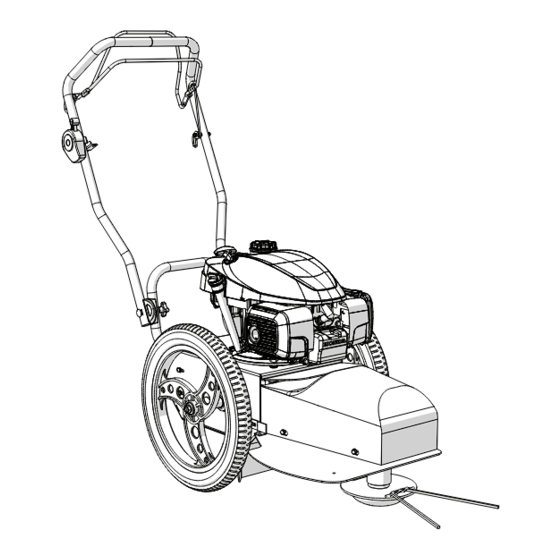
MACHINE PREPARATION MACHINE PREPARATION Packaging contents The machine is delivered already assembled and does not require an assembly of the components. For space reasons, the handlebar is folded. The packaging contents are as follows: • the machine body; • the tool bag; •... - Page 12 MACHINE PREPARATION To open the handlebar (1) in FLO 6 models: loosen (A) the two side knobs (2) until the handlebar (1) is free to rotate. Adjust (B) the handlebar (1) inclination as required. Tighten (C) the two side knobs (2) to secure the handlebar (1) once the optimal working position has been found.
- Page 13 MACHINE PREPARATION To open the handlebar (1) in FLO 7 models: loosen (A) the two side knobs (2) until the handlebar (1) is free to rotate. Adjust (B) the handlebar (1) inclination as required. Tighten (C) the two side knobs (2) to secure the handlebar (1) once the optimal working position has been found.
- Page 14 MACHINE PREPARATION Loosen (D) the handlebar fastening lever (3). Adjust (E) the horizontal rotation of the handlebar (1) as required. Tighten (F) the lever (3) once the optimal horizontal position has been found. Pag. 14 di 34 FLO 6 - FLO 7 Rev.
-
Page 15: Controls Operation
CONTROLS OPERATION CONTROLS OPERATION Starting and stopping the engine. Starting: Move the gas control lever (1) to the “START-MAX” (A) position. Press the fuel primer bulb on the engine carburettor (refer to the engine manual) and pull the starter cord (2) until the machine starts. WARNING If the engine does not start, or in case of other problems relating to the engine, please refer to the engine manual to identify the cause. -
Page 16: Cutting Device Operation
CONTROLS OPERATION Cutting device operation To activate the cutting device: Lift (A) and move (B) the safety hook (2) of the cutting device to deactivate it. Pull the cutting device control lever (3) towards you (C). To deactivate the cutting device: Release (D) the cutting device control lever. -
Page 17: Self-Propelling Operation
CONTROLS OPERATION Self-propelling operation To activate the automatic forward motion of the machine: Select the desired speed and the gear by pushing the speed knob (4) on the rear of the machine. When you push or pull the speed knob (A) you can set the gear to: 1 - slow speed, 2 - intermediate speed, 3 - fast speed. -
Page 18: Maintenance And Adjustments
MAINTENANCE AND ADJUSTMENTS MAINTENANCE AND ADJUSTMENTS In this chapter are described inspections or operations which may need specific technical skill and adequate equipment. It is preferable that these operations are carried out by the retailer or by a qualified assistance centre. CAUTION Before starting these operations, switch off the engine if running, disconnect the spark plug and, in the case of machines with electric start or automatic starting devices, remove the starting keys or any similar device. -
Page 19: Adjustments
MAINTENANCE AND ADJUSTMENTS Adjustments The cables are adjusted by moving the adjuster on the thrust plate of the handlebar, to lengthen or shorten the cable, thus stretching or slackening the transmission. 6.3.1 To increase cable tension Remove (A) the protective cap (3). Slacken off (B) the nut (4) bringing it to the desired position. -
Page 20: To Slacken The Cable Tension
MAINTENANCE AND ADJUSTMENTS 6.3.2 To slacken the cable tension Remove (A) the protective cap (3). Slacken off (B) the nut (6) bringing it to the desired position. Push (C) the adjuster (5) upwards, until the nut (6) rests on the thrust plate. Tighten (D) the nut (4) against the thrust plate. -
Page 21: Cutting Device Coupling Control Transmission
MAINTENANCE AND ADJUSTMENTS 6.3.3 Cutting device coupling control transmission Use this adjustment when it is necessary to modify belt tension. It is necessary to stretch the belt further when there are signs of sliding (cutting ineffectiveness, smoke emission from the belt housing, belt screeching etc.) and slacken their tension if, due to excessive tension, the cutting device remains coupled despite the fact that the lever has been released. -
Page 22: Cutting Belt Centre Distance Adjustment
MAINTENANCE AND ADJUSTMENTS 6.3.5 Cutting belt centre distance adjustment After some hours of operation, the cutting device transmission belt setting may grow longer. If the belt is too long, it will not manage to transmit the necessary power to the cutting device, slipping on the pulley and rapidly deteriorating. -
Page 23: Blade Brake Shoe
MAINTENANCE AND ADJUSTMENTS 6.3.6 Blade brake shoe If the braking capacity of the cutting device is inadequate it is possible to adjust the brake shoe (9) as follows: Switch off the machine. Remove the protective nose. Check that the brake shoe is not actually able to provide braking. Slacken off the tension of the cable by adjusting the dedicated handlebar adjuster (see "6.3.2 To slacken the cable tension") or the tensioner (10). -
Page 24: Transport And Storage
TRANSPORT AND STORAGE TRANSPORT AND STORAGE Transport To reduce the machine dimensions for transport or storage, the handlebar can be folded (A) by slackening off (B) the two fastening knobs (1); make sure that the cable bend radii are not excessively small. The machine must be lifted by at least two people, holding it from the sides. Storage Never store the machine with fuel in the tank inside a building where the vapours may be reached by a flame or sparks. -
Page 25: Cutting Devices
CUTTING DEVICES CUTTING DEVICES The machine, sold complete with line cutting device, can also be equipped with the blade cutting device, which can be purchased at a later date. CAUTION Before starting these operations, switch off the engine if running, disconnect the spark plug and, in the case of machines with electric start or automatic starting devices, remove the starting keys or any similar device. -
Page 26: Dissembling
CUTTING DEVICES 8.1.1 Dissembling To disassemble the cutting system, proceed as follows: Loosen (A) the fixing screw using the appropriate 8 mm Allen key (6) supplied. Remove (B) the cutting unit (7). To remove the nylon guard (8), proceed as follows: Slacken off (A) the rear fixing screws (9). Remove (B) the front screws (10). Remove (C) the guard (8). Pag. -
Page 27: Assembling
CUTTING DEVICES 8.1.2 Assembling To assemble the cutting system, proceed as follows: Insert (A) the upper guard (8) on the blade hub (11) and on the two rear fixing screws (9) (wait before tightening them). Fix (B) the guard to the front attachment by tightening the screws (10). Tighten (C) the rear screws (9). -
Page 28: Replacing The Cutting Elements (Nylon Line)
CUTTING DEVICES 8.1.3 Replacing the cutting elements (Nylon line) Rotate the cutting disk (2) until the fixing slots (12) are in an accessible position with respect to the machine body, and apply the line (13) as shown in the figure. If necessary adjust the two ends to make them of the same length. Tighten the knot by pulling both ends. -
Page 29: Blade Cutting Device
CUTTING DEVICES Blade cutting device For a more effective cutting of shrubs and brushwood, as an alternative to the line cutting system, it is possible to install a blade cutting device. The blade makes it possible to cut thick grass and brushwood, shredding the vegetation left on the ground. In this case the machine and protections comply with the Community standard EN12733. No. -
Page 30: Blade Device Assembling
CUTTING DEVICES 8.2.1 Blade device assembling. CAUTION The assembly operation requires great care and attention to detail and must be carried out by a suitably trained person. Disconnect the spark plug cap and keep it away from the spark plug to prevent accidental ignition. - Page 31 CUTTING DEVICES Attach (F) the blade guard with the two screws (7) under the mower unit / machine frame. When the guard is correctly positioned, tighten (G) the front screws (7) fully and then tighten (H) the two rear screws (6) on the mower unit. Insert the spring washer (13) on the blade fixing screw (12) first, followed by the lock washer (14).
- Page 32 CUTTING DEVICES Fix the slide (15) on the side holes of the blade guard with the relative screws (16), washers (17) and nuts. Adjust the cutting height if necessary by using the side holes of the slide, choosing the height of the blade position and fastening everything with the four screws. Lower (I) the machine by resting it on the slide.
- Page 33 CUTTING DEVICES CAUTION If you must work in conditions of very high or wet grass or grass with particular structure, the cutting device might tend to get bogged down. How to recognize the situation: • the engine loses revs; • the belt emits friction noises (screeches and the like);...
-
Page 34: Warranty
WARRANTY WARRANTY Our company guarantees the correct working of all agricultural and industrial machines made by us for a period of 24 months (12 months for professional use) from the time of purchase. The applicable warranty period for the product is calculated from the date of the sales receipt and / or invoice. - Page 35 TYPE / TYP / TYPE / TIPO / TIPO / TYPE / TYPE / TIPO / MALLI / TYPBE / TYPE / ΤΥΠΟΣ / TYP: FLO Speed 6BS / FLO Speed 7BS, FLO Pro Speed 6BS / FLO Pro Speed 7BS , FLO Speed 6HO / FLO Speed 7HO , FLO Pro Speed 6HO / FLO Pro Speed 7HO, FLO Speed 6 LC / FLO Speed 7 LC c) Il prodotto è...
- Page 36 BLUE BIRD INDUSTRIES Fabbrica Motori s.r.l. Via Due Camini, 19 36010 ZANÉ ITALIA Tel. 0445 314138 Fax 0445 314225 www.bluebirdind.com...
Need help?
Do you have a question about the FLO Speed 6BS and is the answer not in the manual?
Questions and answers