Table of Contents
Advertisement
Advertisement
Table of Contents

Related Manuals for Jonker Sailplanes JS3 RES


Summary of Contents for Jonker Sailplanes JS3 RES
- Page 3 JS-MD 3 RES Maintenance Manual MD11-AMM-00-002 Supplement Issue: 00 JS-MD 3 RES MAINTENANCE MANUAL SUPPLEMENT Type: JS-MD Single Model: JS-MD 3 RES Serial number: Registration Number: Document Number: MD11-AMM-00-002 Title: JS-MD 3 RES Maintenance Manual Supplement Issue: Date of issue: 23 May 2022 Uys Jonker Digitally signed by Uys Jonker...
- Page 4 JS-MD 3 RES Maintenance Manual MD11-AMM-00-002 Supplement Issue: 00 Intentionally left blank Rev. 00 Rev. Date: 23-May-22 Page ii...
- Page 5 JS-MD 3 RES Maintenance Manual MD11-AMM-00-002 Supplement Issue: 00 0 GENERAL This Maintenance Manual has been prepared to provide maintenance personnel with the necessary information to maintain the JS-MD 3 RES System. All the data required to be furnished to the pilot and the maintenance personnel, by the Airworthiness Requirement CS- 22, is contained in this manual.
- Page 6 JS-MD 3 RES Maintenance Manual MD11-AMM-00-002 Supplement Issue: 00 List of effective sections Number of Section Revision Date Reference Pages 23.05.2022 23.05.2022 23.05.2022 23.05.2022 23.05.2022 23.05.2022 23.05.2022 23.05.2022 23.05.2022 23.05.2022 23.05.2022 23.05.2022 23.05.2022 23.05.2022 23.05.2022 23.05.2022 23.05.2022 23.05.2022 Rev. 00 Rev.
- Page 7 JS-MD 3 RES Maintenance Manual MD11-AMM-00-002 Supplement Issue: 00 Record of Amendments Date of Date of Issue/ Revision Signature Insertion Rev. 00 Rev. Date: 23-May-22 Page 0–3...
-
Page 8: Table Of Contents
JS-MD 3 RES Maintenance Manual MD11-AMM-00-002 Supplement Issue: 00 Table of Contents General ........................0–1 Record of Revisions .................... 0–1 List of effective sections ..................0–2 Record of Amendments ..................0–3 Table of Contents ....................0–4 List of Figures ...................... 0–7 List of Tables ....................... - Page 9 JS-MD 3 RES Maintenance Manual MD11-AMM-00-002 Supplement Issue: 00 Fire warning system ................... 4-79 Calibration & setup ....................5-1 Actuator system setup ..................5-1 Actuator calibration ....................5-4 Main door setup....................5-4 Motor resolver calibration ..................5-5 Propeller alignment ....................5-6 Wiring loom .......................
- Page 10 JS-MD 3 RES Maintenance Manual MD11-AMM-00-002 Supplement Issue: 00 Maintenance mode ..................... 8-11 Setup menu ......................8-11 Charge mode ..................... 8-12 Fire warning system ................... 8-12 Software/ Firmware update ..................9-1 Requirements for firmware updated..............9-1 DCU firmware update ................... 9-1 RFU firmware update ...................
-
Page 11: List Of Figures
JS-MD 3 RES Maintenance Manual MD11-AMM-00-002 Supplement Issue: 00 List of Figures Figure 1-1 JS3 with RES pylon extended ................1-1 Figure 2-1 RES System overview..................2-1 Figure 2-2 Kinematics layout overview ................2-2 Figure 2-3 Electrical system overview ................2-3 Figure 2-4 Electrical interaction overview ................ - Page 12 JS-MD 3 RES Maintenance Manual MD11-AMM-00-002 Supplement Issue: 00 Figure 6-15 LXNAV bridge ....................6-16 Figure 6-16 LXNAV bridge wiring ..................6-16 Figure 6-17 Interlock and HV wiring ................. 6-18 Figure 6-18 Charge connector termination plug ............... 6-18 Figure 6-19 Battery connector termination plug ..............6-19 Figure 7-1 Lubrication points ....................
- Page 13 JS-MD 3 RES Maintenance Manual MD11-AMM-00-002 Supplement Issue: 00 List of Tables Table 1-1 RES Technical Data ................... 1-1 Table 2-1 Electrical loads ....................2-5 Table 3-1 Life Limits Durations ................... 3-1 Table 4-1 Maintenance Requirement Schedule..............4-1 Table 4-2 Actuator specifications ..................4-4 Table 4-3 DC-DC converter specifications ..............
- Page 14 JS-MD 3 RES Maintenance Manual MD11-AMM-00-002 Supplement Issue: 00 Intentionally left blank Rev. 00 Rev. Date: 23-May-22 Page 0–10...
-
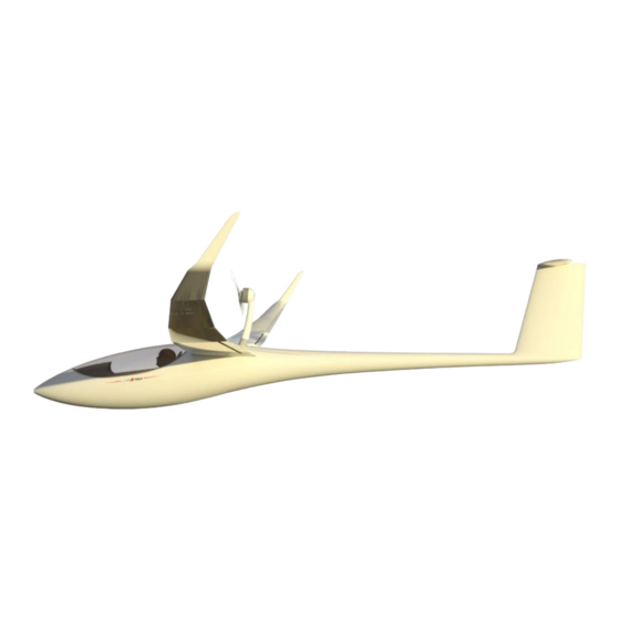
Page 15: General
JS-MD 3 RES Maintenance Manual MD11-AMM-00-002 Supplement Issue: 00 1 GENERAL Descriptive data The JS-MD 3 RES System is an electric propulsion system used for self take-off or sustained flight when soaring conditions become unfavorable. Propulsion is made possible using a 2- bladed propeller powered by an electric motor mounted on a retractable pylon in the rear section of the fuselage. - Page 16 JS-MD 3 RES Maintenance Manual MD11-AMM-00-002 Supplement Issue: 00 Intentionally left blank Rev. 00 Rev. Date: 23-May-22 Page 1-2...
-
Page 17: Description Of Systems And Components
JS-MD 3 RES Maintenance Manual MD11-AMM-00-002 Supplement Issue: 00 2 DESCRIPTION OF SYSTEMS AND COMPONENTS Introduction and overview The RES system can be divided into two main systems, the kinematic system, and the electrical system. Figure 2-1 RES System overview Rev. -
Page 18: Res Kinematics Overview
JS-MD 3 RES Maintenance Manual MD11-AMM-00-002 Supplement Issue: 00 RES kinematics overview Kinematics layout overview The pylon extension/retraction kinematic system is contained inside the fuselage bay and controls the pylon position as well as the operation of the main doors. Figure 2-2 Kinematics layout overview This system is comprised of a single pylon, for the mounting of the motor, driven by an electromechanical actuator. -
Page 19: Electrical System Overview
JS-MD 3 RES Maintenance Manual MD11-AMM-00-002 Supplement Issue: 00 Electrical system overview Electrical overview The electrical system consists of various components as illustrated in Figure 2-3: Figure 2-3 Electrical system overview Rev. 00 Rev. Date: 23-May-22 Page 2-3... - Page 20 JS-MD 3 RES Maintenance Manual MD11-AMM-00-002 Supplement Issue: 00 Electrical components The electrical system consists of the following electrical components: • HV Batteries (removable) • Avionic Batteries (removable) • Display and control unit (DCU) • Motor Controller assembly • Cooling system •...
-
Page 21: Figure 2-4 Electrical Interaction Overview
JS-MD 3 RES Maintenance Manual MD11-AMM-00-002 Supplement Issue: 00 Figure 2-4 Electrical interaction overview Electrical loads Electrical loads protection required for the system is given in Table 2-1. Operating Voltage Peak Current Component RES propulsion system 270-400 Motor controller Motor controller cooling fans Actuator 11.5 DC-DC converter (400V-14.4V) - Page 22 JS-MD 3 RES Maintenance Manual MD11-AMM-00-002 Supplement Issue: 00 Intentionally left blank Rev. 00 Rev. Date: 23-May-22 Page 2-6...
-
Page 23: Airworthiness Limitations And Inspections
JS-MD 3 RES Maintenance Manual MD11-AMM-00-002 Supplement Issue: 00 3 AIRWORTHINESS LIMITATIONS AND INSPECTIONS Airworthiness limitations Table 3-1 lists the life limits that should not be exceeded. When these limits have been reached, the affected component must be returned to the manufacturer or an approved maintenance organisation so that the required maintenance activities or inspections can be performed. - Page 24 JS-MD 3 RES Maintenance Manual MD11-AMM-00-002 Supplement Issue: 00 Intentionally left blank Rev. 00 Rev. Date: 23-May-22 Page 3-2...
-
Page 25: Maintenance Schedule
JS-MD 3 RES Maintenance Manual MD11-AMM-00-002 Supplement Issue: 00 4 MAINTENANCE SCHEDULE WARNING: Before any maintenance, the HV batteries should be removed. WARNING: Only OEM and authorised organisations are allowed to maintain high voltage components. Annual inspection A mandatory annual inspection is required for issuing the Airworthiness Review Certificate. NOTE: Some regulating authorities require one-year or 100 hour-interval inspections. -
Page 26: Res Actuator Assembly
JS-MD 3 RES Maintenance Manual MD11-AMM-00-002 Supplement Issue: 00 RES actuator assembly The actuator assembly is responsible for the retraction and extension of the pylon. It consists of the following components as illustrated in Figure 4-1. No Description No Description Actuator Pylon bell crank Pylon bell crank bracket... - Page 27 JS-MD 3 RES Maintenance Manual MD11-AMM-00-002 Supplement Issue: 00 Actuator The assembly is driven by a 12 V actuator which is controlled by the DCU and RFU. The actuator has built-in limit switches and a hall effect sensor to monitor the extension and retraction of the pylon.
-
Page 28: Figure 4-2 Actuator Assembly
JS-MD 3 RES Maintenance Manual MD11-AMM-00-002 Supplement Issue: 00 Figure 4-2 Actuator assembly 4.2.1.2 Specification Table 4-2 Actuator specifications Parameter Value Part Number 107 09 230 00 Input voltage Maximum current 11.6A 4.2.1.3 Removal 1. Extend the pylon to a position slightly below the extended position. 2. -
Page 29: Figure 4-3 Pylon Bell Crank Assembly
JS-MD 3 RES Maintenance Manual MD11-AMM-00-002 Supplement Issue: 00 7. Remove the pylon support. 8. Install the main doors. NOTE: The actuator system and main door setup must be done again to ensure the kinematic system is working correctly. Refer to the Calibration & setup section. - Page 30 JS-MD 3 RES Maintenance Manual MD11-AMM-00-002 Supplement Issue: 00 5. Remove the Actuator bolt (2). 6. Remove the Pylon driver arm bolt (4). 7. Remove the Pylon bell crank bracket bolt (1). 4.2.2.3 Installation 1. Install the Pylon bell crank bracket bolt (1). 2.
-
Page 31: Figure 4-4 Pylon Bell Crank Bracket Assembly
JS-MD 3 RES Maintenance Manual MD11-AMM-00-002 Supplement Issue: 00 Pylon bell crank bracket The pylon bell crank bracket is located at the bottom of the rear fuselage compartment and fastened to the bottom of the fuselage using four fastening nuts as illustrated in Figure 4-4. 4.2.3.1 Overview No Description No Description... - Page 32 JS-MD 3 RES Maintenance Manual MD11-AMM-00-002 Supplement Issue: 00 4.2.3.3 Installation 1. Install the Pylon bell crank bracket (5) by fastening the four Pylon bell crank bracket bolts (4). 2. Install the Pylon bell crank bracket bolt (1). 3. Install a new Door close cable (3). 4.
-
Page 33: Figure 4-5 Pylon Driver Arm Assembly
JS-MD 3 RES Maintenance Manual MD11-AMM-00-002 Supplement Issue: 00 Pylon driver arm The pylon driver arm is connected to the pylon and pylon bell crank as illustrated in Figure 4-5. 4.2.4.1 Overview No Description No Description Pylon bell crank Pylon driver arm bush Pylon driver arm Pylon driver arm lock Pylon driver arm nut... - Page 34 JS-MD 3 RES Maintenance Manual MD11-AMM-00-002 Supplement Issue: 00 6. Loosen the Pylon driver arm bolt (6) and nut (5) to free the Pylon driver arm (3). 7. The Pylon driver arm lock (4) can be replaced by loosening the Pylon driver arm lock bolt (10).
-
Page 35: Res Pylon
JS-MD 3 RES Maintenance Manual MD11-AMM-00-002 Supplement Issue: 00 RES Pylon The pylon is the main structural component connecting the motor to the fuselage of the aircraft. The pylon is a dynamic component that is extended and retracted into the fuselage of the aircraft by the actuator assembly. -
Page 36: Propeller
JS-MD 3 RES Maintenance Manual MD11-AMM-00-002 Supplement Issue: 00 No Description No Description EMRAX 208 Electrical motor Locking wire Propeller bolt Pylon cover Propeller ring Pylon Propeller Pylon nut Pylon driver bush Washer Pylon driver bolt Pylon base bracket bolt Pylon base bracket Pylon Sleeve nut Pylon base bush... - Page 37 JS-MD 3 RES Maintenance Manual MD11-AMM-00-002 Supplement Issue: 00 4. Electrical motor section. NOTE: It is advisable to remove the motor as it makes the handling of the pylon easier. 5. Disconnect the pylon driver arm by loosening the Pylon driver bolt (11) 6.
-
Page 38: Figure 4-7 Motor Wires Routing
JS-MD 3 RES Maintenance Manual MD11-AMM-00-002 Supplement Issue: 00 2. Electrical motor section). NOTE: The motor wires should pass the pylon sleeve on the front side of the pylon for a neater installation. Front side Figure 4-7 Motor wires routing 3. -
Page 39: Figure 4-8 Propeller Assembly
JS-MD 3 RES Maintenance Manual MD11-AMM-00-002 Supplement Issue: 00 10. Electrical motor section). Propeller The RES propeller is manufactured by Technoflug. The KS1 is a two-blade fixed-pitch propeller. The propeller is fastened directly to the EMRAX 208 Electrical motor by six fastening bolts as illustrated Figure 4-8. - Page 40 JS-MD 3 RES Maintenance Manual MD11-AMM-00-002 Supplement Issue: 00 WARNING: Avoid aggressive media like acetone as this could ruin the surface finish. 4.4.2.2 Inspections After 25 hours of operation the operator or AMO must inspect the propeller after washing it thoroughly for any cracks and raptures.
- Page 41 JS-MD 3 RES Maintenance Manual MD11-AMM-00-002 Supplement Issue: 00 the propeller alignment must be recalibrated (refer to the Calibration & setup section). Installation WARNING: The propeller must be statically balanced before fitment and it is recommended to verify the vibrations caused by the propeller by having it dynamic balanced. Excessive vibrations could cause damage or destroy the propeller and other components.
- Page 42 JS-MD 3 RES Maintenance Manual MD11-AMM-00-002 Supplement Issue: 00 Change of leading-edge protection The following procedure can be followed if a new protection tape is necessary. (M3 Scotch 8562, 25 mm Artikel-Nr. 3856225300) It is also available at the manufacturer. Do not use other materials. 1.
-
Page 43: Electrical Motor
JS-MD 3 RES Maintenance Manual MD11-AMM-00-002 Supplement Issue: 00 Electrical motor The Emrax 208 HV is located at the top of the pylon and is fastened using 6x M8 bolts. The motor has three High voltage terminals and a tandem motor resolver setup. Overview No Description No Description... - Page 44 JS-MD 3 RES Maintenance Manual MD11-AMM-00-002 Supplement Issue: 00 Maintenance & checks The Emrax 208 motor and controller must be maintained according to Solo Flugzeugbau Motor Overhaul Manual. Servicing must be done at maintenance organisations approved to perform the maintenance. Removal 1.
- Page 45 JS-MD 3 RES Maintenance Manual MD11-AMM-00-002 Supplement Issue: 00 Installation 1. Make sure the Resolver plate (7) is fitted to the Emrax 208 HV (1) motor and in the correct orientation. The Alignment marks (11) must lign up. WARNING: The Resolver plate (7) has a specific orientation to the Motor. If this orientation is changed, the calibration of the resolvers will be out.
-
Page 46: Res Doors
JS-MD 3 RES Maintenance Manual MD11-AMM-00-002 Supplement Issue: 00 RES doors The RES doors consist of the main doors and the front doors. During full extension, the main doors close for aerodynamic purposes, and the front doors serve as the opening for the pylon. The main doors are operated by the main door bell crank. - Page 47 JS-MD 3 RES Maintenance Manual MD11-AMM-00-002 Supplement Issue: 00 Main door bell crank The main door bell crank consists of multiple assemblies as illustrated in Figure 4-11. 4.6.2.1 Overview Rev. 00 Rev. Date: 23-May-22 Page 4-23...
-
Page 48: Figure 4-11 Main Door Bell Crank Assembly
JS-MD 3 RES Maintenance Manual MD11-AMM-00-002 Supplement Issue: 00 No Description No Description Spring link Spring bush Spring bolt Bell crank stop Spring arm Spring Bell crank pin R-pin Thimble Crimp Sleeve Spring lug Door close cable Pully bracket Pulley Pulley bolt Cable adjuster bolt Cable adjuster... - Page 49 JS-MD 3 RES Maintenance Manual MD11-AMM-00-002 Supplement Issue: 00 3. Connect the Pushrod (21) to the bell crank and fix it in place using the Pushrod fastening nut (20). CAUTION: Removing and installing the pushrod, could result in a length adjustment. In this case, the door setup should be done again (refer to the Calibration &...
-
Page 50: Figure 4-12 Main Doors Assembly
JS-MD 3 RES Maintenance Manual MD11-AMM-00-002 Supplement Issue: 00 Main doors The main doors consist of a left and right door as illustrated in Figure 4-12. Overview No Description No Description Front door hinges Right main door Left main door Door hinge top Pushrod bolt Hinge bolt... - Page 51 JS-MD 3 RES Maintenance Manual MD11-AMM-00-002 Supplement Issue: 00 4.6.4.1 Maintenance & Checks The main doors are should seat properly during full pylon retraction and extension. The main doors should not touch the outside of the fuselage when they are fully open. The doors should open and close smoothly –...
-
Page 52: Figure 4-13 Front Doors Assembly
JS-MD 3 RES Maintenance Manual MD11-AMM-00-002 Supplement Issue: 00 Front doors The front doors are fixed to the main doors and are spring operated as illustrated in Error! Reference source not found.: Overview Description Description Right front door Left front door Front door hinge bolt Front door bottom hinge Front door top hinge... - Page 53 JS-MD 3 RES Maintenance Manual MD11-AMM-00-002 Supplement Issue: 00 4.7.1.1 Removal 1. Extend the pylon to a position slightly below the extended position to ensure the main doors are fully open. 2. Switch off the RES master switch. NOTE: The main doors could be removed first to improve the ease of access. 3.
-
Page 54: Battery Latches
JS-MD 3 RES Maintenance Manual MD11-AMM-00-002 Supplement Issue: 00 Battery latches The battery latches are located within the rear fuselage compartment. There are two battery latches, one for the left battery and the other for the right battery. They are critical in ensuring that the HV batteries are fastened in flight. - Page 55 JS-MD 3 RES Maintenance Manual MD11-AMM-00-002 Supplement Issue: 00 Removal 1. Extend the pylon to a position slightly below the extended position to ensure the main doors are fully open. 2. Switch off the RES master switch. 3. Remove the R-pin (5). 4.
-
Page 56: Display And Control Unit (Dcu)
JS-MD 3 RES Maintenance Manual MD11-AMM-00-002 Supplement Issue: 00 Display and Control Unit (DCU) The Display and Control Unit (DCU) is located on the instrument within the cockpit. The DCU provides the interface between the Pilot and the system. The DCU provides commands to the RFU and Motor controller to control the system. - Page 57 JS-MD 3 RES Maintenance Manual MD11-AMM-00-002 Supplement Issue: 00 Rev. 00 Rev. Date: 23-May-22 Page 4-33...
- Page 58 JS-MD 3 RES Maintenance Manual MD11-AMM-00-002 Supplement Issue: 00 Installation 1. Install the DCU into the instrument panel and fastening it using the four fastening screws located in the corners of the DCU. CAUTION: Be careful not to disturb or damage other wires within the binnacle when installing the DCU.
-
Page 59: Lxnav Bridge
JS-MD 3 RES Maintenance Manual MD11-AMM-00-002 Supplement Issue: 00 LXNAV Bridge Overview The LXNAV bridge is an optional extra. The bridge provides an interface between the DCU and LXNAV flight computers. This enables the LXNAV flight computer to be able to display various parameters of the RES system like HV battery SOC, RPM, Motor controller temperature, etc. -
Page 60: Motor Controller Assembly
JS-MD 3 RES Maintenance Manual MD11-AMM-00-002 Supplement Issue: 00 Motor controller assembly The motor controller regulates the operation of the electrical motor. The motor controller assembly consists of the motor controller unit and the controller cooling assembly. There are two variants avaible, namely the air cooled system and the water cooled system. WARNING: Only OEM or authorised persons are allowed to maintain high voltage components like the motor controller assembly. -
Page 61: Figure 4-16 Motor Controller Overview
JS-MD 3 RES Maintenance Manual MD11-AMM-00-002 Supplement Issue: 00 Motor controller assembly B5 bulkhead Controller cooling fan plate Figure 4-16 Motor controller overview 4.11.1.2 Removal Description Description Motor Controller box cover B5 Cover Bugwiper connector back plate Front fastening bolt Ground bolt Cable glands Rev. - Page 62 JS-MD 3 RES Maintenance Manual MD11-AMM-00-002 Supplement Issue: 00 Rear fastening bolt Cooling fan Controller cooling fan plate Grommet D-sub connectors Box top Box bottom High voltage ring terminals Figure 4-17 Motor controller assembly 4.11.1.2.1 Removal of the motor controller assembly from the fuselage 1.
- Page 63 JS-MD 3 RES Maintenance Manual MD11-AMM-00-002 Supplement Issue: 00 10. Loosen the two Rear fastening bolts (7) and three Front fastening bolts (4). 11. Remove the motor controller assembly from the fuselage. Be careful to clear all wiring while removing the assembly as the wiring loom can be damaged. Rev.
-
Page 64: Figure 4-19 Motor Controller Pcbs
JS-MD 3 RES Maintenance Manual MD11-AMM-00-002 Supplement Issue: 00 4.11.1.2.2 Removal of the motor controller assembly PCBs Three PCBs are located within the motor controller assembly as illustrated in Figure 4-19: No Description No Description Box top fasterning bolts RCB PCB Fastening bolts Ribbon cable Motor controller PCB D-sub assembly... - Page 65 JS-MD 3 RES Maintenance Manual MD11-AMM-00-002 Supplement Issue: 00 1. Remove the motor controller Box Top (12) by removing the six Box top fastening bolts (14). 2. Lift the Box Top (12) from the bottom assembly. CAUTION: Do not lift it too far away, as the Ribbon cable (16) must be disconnected from the D-sub assembly first.
- Page 66 JS-MD 3 RES Maintenance Manual MD11-AMM-00-002 Supplement Issue: 00 4.11.1.2.3 Removal of the cooling fans There are two cooling fans located behind the motor controller assembly. These fans can be accessed from the rear fuselage compartment or the cockpit if the motor controller assembly is removed.
- Page 67 JS-MD 3 RES Maintenance Manual MD11-AMM-00-002 Supplement Issue: 00 4.11.1.3 Installation The installation of the motor assembly consists of the following three installation procedures: • Installation of the cooling fans • Installation of the motor controller assembly PCBs • Installation of the motor controller assembly into the fuselage 4.11.1.3.1 Installation of the cooling fans 1.
- Page 68 JS-MD 3 RES Maintenance Manual MD11-AMM-00-002 Supplement Issue: 00 6. Insert the motor controller assembly back into the fuselage. Be sure not to disturb any wiring when inserting the motor controller assembly. WARNING: There are wires which are routed from the right side of the fuselage to the left by passing underneath the motor controller.
-
Page 69: Figure 4-22 Hv Wire
JS-MD 3 RES Maintenance Manual MD11-AMM-00-002 Supplement Issue: 00 The high voltage wires should be installed in the correct sequence, if not – the WARNING: system could be damaged. 4. Fasten the five bolts retaining the High voltage ring terminals (12). WARNING: The high voltage terminals should be fastened correctly. - Page 70 JS-MD 3 RES Maintenance Manual MD11-AMM-00-002 Supplement Issue: 00 13. Install the B5 cover (2) by fastening the four bolts located in the corner of the cover. 14. The system can now be switched on to verify that there are no errors. WARNING: No warning will be displayed if the cooling fans are not connected correctly.
- Page 71 JS-MD 3 RES Maintenance Manual MD11-AMM-00-002 Supplement Issue: 00 Water cooled motor controller assembly The water cooled motor controller assembly is installed above the wheel box between Bulkhead B7 and B8 below the wing spars. The controller board is housed in a aluminium enclosure. High voltage wiring is connected to the rear of the motor controller assembly, facing the tail of the aircraft.
- Page 72 JS-MD 3 RES Maintenance Manual MD11-AMM-00-002 Supplement Issue: 00 4.11.2.2 Removal Removal of the Liquid Cooling System consists of the draining of the liquid out of the cooling system, removal of the radiator system and the removal of the motor controller box from the fuselage.
- Page 73 JS-MD 3 RES Maintenance Manual MD11-AMM-00-002 Supplement Issue: 00 Rev. 00 Rev. Date: 23-May-22 Page 4-49...
- Page 74 JS-MD 3 RES Maintenance Manual MD11-AMM-00-002 Supplement Issue: 00 4.11.2.2.2 Removal of the motor controller assembly from the fuselage Description Description Glove box assembly Master batteries Figure 4-25 Glove box and battery removal 1. Disconnect the Bug wiper connector back plate (8) by loosening its two fastening bolts. 2.
- Page 75 JS-MD 3 RES Maintenance Manual MD11-AMM-00-002 Supplement Issue: 00 4.11.2.2.3 Motor controller box removal Description Description Motor controller assembly Elbow fitting Mounting bolt D-sub connectors Glove box assembly RFU-Isometer assembly RCB PCB assembly Bug wiper connector back plate Cable glands High voltage wires Motor controller Lid High voltage ring terminals...
- Page 76 JS-MD 3 RES Maintenance Manual MD11-AMM-00-002 Supplement Issue: 00 Figure 4-26 Motor controller assembly view 1. Ensure the HV batteries are removed and RES master switch is OFF. 2. Remove the connectors to the RFU-Isometer assembly (6) and the RCB PCB assembly (7).
- Page 77 JS-MD 3 RES Maintenance Manual MD11-AMM-00-002 Supplement Issue: 00 Caution: Clear all wiring while removing the assembly as the wiring loom can be damaged. Rev. 00 Rev. Date: 23-May-22 Page 4-53...
- Page 78 JS-MD 3 RES Maintenance Manual MD11-AMM-00-002 Supplement Issue: 00 4.11.2.2.4 Removal of the motor controller assembly PCBs Two PCBs are located within the motor controller assembly: • Motor controller PCB • D-sub assembly Description Description Cold Plate Cold plate mount bolts Position to hold motor controller Box assembly assembly...
- Page 79 JS-MD 3 RES Maintenance Manual MD11-AMM-00-002 Supplement Issue: 00 1. Disconnect the ribbon cable from the D-sub assembly (4). 2. Remove the D-sub assembly to be able to gain access to the motor controller PCB. 3. Unfastened the Cold Plate mount bolts (16). 4.
- Page 80 JS-MD 3 RES Maintenance Manual MD11-AMM-00-002 Supplement Issue: 00 4.11.2.2.5 Removal of radiator assembly The radiator assembly is supported by the Radiator support plate (1) Description Description Radiator support plate Radiator Water pump Water pump bracket Radiator mounting bolts Water pump mounting bolt Figure 4-29 Radiator assembly 1.
-
Page 81: Dc-Dc Converter
JS-MD 3 RES Maintenance Manual MD11-AMM-00-002 Supplement Issue: 00 4.11.2.2.6 Removal of DC-DC converter and RCB PCB Description Description DC-DC converter DC-DC converter mounting bolts RCB PCB assembly RCB PCB mounting bolt DC-DC converter brackets Figure 4-30 DC-DC Converter and RCB PCB assembly 1. - Page 82 JS-MD 3 RES Maintenance Manual MD11-AMM-00-002 Supplement Issue: 00 4.11.2.3 Installation Installation of the liquid cooling system and the motor controller assembly consists of the following installation procedures: • Installation of the motor controller system, DC-DC converter and RCB PCB assembly into the fuselage.
- Page 83 JS-MD 3 RES Maintenance Manual MD11-AMM-00-002 Supplement Issue: 00 5. Fasten the cold plate to the motor controller box with M3 size bolts. 6. Install the D-sub assembly (4) into the box and fasten into position. 7. Connect the ribbon cable from the Motor controller PCB (13) to the D-sub assembly. WARNING: If the ribbon cable is not connected, the motor controller will not work.
-
Page 84: Figure 4-20 Cooling Fans
JS-MD 3 RES Maintenance Manual MD11-AMM-00-002 Supplement Issue: 00 Figure 4-31 Motor controller HV wire sequence 13. Tighten the three Cable glands (9). Ground wire mounting point 14. Install ground wire to motor controller PCB and ground bolt, connecting to the box. WARNING: If the ground wiring is not connected to the Motor Controller PCB (13) the motor and motor controller will not operate correctly. - Page 85 JS-MD 3 RES Maintenance Manual MD11-AMM-00-002 Supplement Issue: 00 Figure 4-32 18. Install the D-sub connectors located on the left and right side of the motor controller assembly. 19. Install the Glove box assembly (5) 20. Route the battery cable through the grommet which is located in the glove box assembly.
- Page 86 JS-MD 3 RES Maintenance Manual MD11-AMM-00-002 Supplement Issue: 00 4.11.2.3.2 Radiator system installation Description Description Radiator support plate Radiator Radiator mounting bolts Fan guard Washers Figure 4-33 Radiator system installation 1. Install Fan guard (32), Washers (33) and Radiator mounting bolts (25) to Radiator support plate (20).
- Page 87 JS-MD 3 RES Maintenance Manual MD11-AMM-00-002 Supplement Issue: 00 4.11.2.3.3 Piping system installation This section focusses on the correct installation of the piping system of the liquid cooling system. The piping system includes the pump assembly, the expansion cylinder and transfer tubes.
- Page 88 JS-MD 3 RES Maintenance Manual MD11-AMM-00-002 Supplement Issue: 00 Description Description B9-1 Engine bay water lines Pylon tower Battery bed Battery latch Mixer system Water pump reducer Threaded inline fitting Threaded elbow fitting No-spill fitting Tee fitting Elbow fitting Water line from cold plate Water line to cold plate Rev.
- Page 89 JS-MD 3 RES Maintenance Manual MD11-AMM-00-002 Supplement Issue: 00 Figure 4-34 Radiator and water pump connections WARNING: Make sure that all water transfer pipes are correctly installed into the fittings to avoid leakages that can cause damage to the motor controller. 1.
- Page 90 JS-MD 3 RES Maintenance Manual MD11-AMM-00-002 Supplement Issue: 00 Description Description Expansion cylinder lid Spring (OD15x60x1) Expansion cylinder piston O-ring 25x2.5 Expansion cylinder sleeve Figure 35 Expansion cylinder assembly 9. Install the Expansion cylinder assembly according to Figure 40. 4.11.2.4 Maintenance 4.11.2.4.1 Bleeding of the system In this section, the bleeding process of the liquid cooling system is described.
- Page 91 JS-MD 3 RES Maintenance Manual MD11-AMM-00-002 Supplement Issue: 00 4.11.2.4.2 Coolant Mixture Ambient Temperature Propylene Glycol Distilled Water during operation / storage (Coolant) >0°C Not required Between 0°C and -12°C Between -12°C and -18°C Between -15°C and -21°C 4.11.2.4.3 Inserting Coolant to the water system Bleeding reservoir Pressure side connection Suction side connection...
- Page 92 JS-MD 3 RES Maintenance Manual MD11-AMM-00-002 Supplement Issue: 00 3. Place the bleeding reservoir above the liquid cooling system. 4. Add coolant to the bleeding reservoir (ensure that the coolant fills the suction hose of the pump) 5. When the suction hose of the pump is filled, fill the reservoir with coolant 6.
- Page 93 JS-MD 3 RES Maintenance Manual MD11-AMM-00-002 Supplement Issue: 00 11. Lightly tap the pipes. 12. Turn off the pump. 13. Level out the fuselage. The system is completely bled when the pump is turned on and no cavitation noises are present.
-
Page 94: Table 4-3 Dc-Dc Converter Specifications
JS-MD 3 RES Maintenance Manual MD11-AMM-00-002 Supplement Issue: 00 Inspection steps: 1. Inspect the coolant tubes, radiator and cold plate for leakage. Warning: If leakage is present, it is an indication that the coolant level is not at the required level for operation. This can cause damage to the motor controller as the motor controller will over heat. - Page 95 JS-MD 3 RES Maintenance Manual MD11-AMM-00-002 Supplement Issue: 00 Overview No Description No Description DC-DC front bracket DC-DC fastening bolts DC-DC converter DC-DC rear bracket Figure 4-36 DC-DC converter Removal 1. Ensure the master switch of the system is switched off. 2.
- Page 96 JS-MD 3 RES Maintenance Manual MD11-AMM-00-002 Supplement Issue: 00 3. Connect the DC-DC converter (3) wires. Rev. 00 Rev. Date: 23-May-22 Page 4-72...
-
Page 97: Retraction And Fuses Unit (Rfu)
JS-MD 3 RES Maintenance Manual MD11-AMM-00-002 Supplement Issue: 00 Retraction and Fuses Unit (RFU) The Retraction and Fuses Unit is responsible for the power distribution. Smart fuses are used in the RFU to protect the system from electric overload. The RFU is fastened to the same bracket as the IMD, which is located on the right side of the wheel box and motor controller. -
Page 98: Insulation Monitoring Device (Imd)
JS-MD 3 RES Maintenance Manual MD11-AMM-00-002 Supplement Issue: 00 Insulation Monitoring Device (IMD) Overview The Insulation Monitoring Device (IMD) is used to protect the system against high voltage leaks. If a high voltage leak is detected by the IMD, the HV system will be interrupted. The IMD is fastened to the same bracket as the RFU, which is located on the right side of the wheel box and motor controller. -
Page 99: Hv Connectors
JS-MD 3 RES Maintenance Manual MD11-AMM-00-002 Supplement Issue: 00 HV Connectors Overview There are three high voltage connectors within the aircraft. One is located in the cockpit, on the left side of the seat (Charge connector). The other two connectors (HV Battery connectors) are located in the rear section of the fuselage. - Page 100 JS-MD 3 RES Maintenance Manual MD11-AMM-00-002 Supplement Issue: 00 The Charge connector (4) is used to charge either one or both of the HV batteries without removing them from the aircraft. Refer to Wiring loom section. When the charge plug is not used to charge the batteries, the correct Termination plug (2) should be used, if not –...
- Page 101 JS-MD 3 RES Maintenance Manual MD11-AMM-00-002 Supplement Issue: 00 7. Use the Pin removal tool to remove the Communication pins (8). The removal tool is slid over the communication pin from the front side - the pin can then be removed to the rear of the connector 8.
- Page 102 JS-MD 3 RES Maintenance Manual MD11-AMM-00-002 Supplement Issue: 00 4.15.4.4 HV connector 1. Fasten the HV connector to the corresponding plate using the two HV Connector fastening bolts (5). 2. Fasten the Battery connector bracket base plate (10) to the supporting structure by fastening the relevant bolts.
-
Page 103: Avionic Batteries
JS-MD 3 RES Maintenance Manual MD11-AMM-00-002 Supplement Issue: 00 Avionic Batteries There are two avionic batteries located within the aircraft. The one battery is located within a hatch in the seatpan, aft of the control stick. The other avionic battery is located behind the seatback. -
Page 104: Fire Warning System
JS-MD 3 RES Maintenance Manual MD11-AMM-00-002 Supplement Issue: 00 Fire warning system The fire warning system is independent of the RES system. It consists of two thermal switches, a heat-sensitive cable section located in the rear fuselage compartment, a 9 V battery, test button, LED, and buzzer. - Page 105 JS-MD 3 RES Maintenance Manual MD11-AMM-00-002 Supplement Issue: 00 Figure 4-42 Location of 9 V Battery Intentionally left blank Rev. 00 Rev. Date: 23-May-22 Page 4-81...
-
Page 106: Calibration & Setup
JS-MD 3 RES Maintenance Manual MD11-AMM-00-002 Supplement Issue: 00 5 CALIBRATION & SETUP Actuator system setup The actuator system must be set up to ensure the Pylon bell crank locks in the extended position and the pylon completely retracts during retraction. 1. -
Page 107: Figure 5-1 Fuselage Clearance
JS-MD 3 RES Maintenance Manual MD11-AMM-00-002 Supplement Issue: 00 Clearance Figure 5-1 Fuselage clearance WARNING: The pylon driver arm must lock into the pylon driver arm lock. If the joint does not fully extend it could overload the supporting structures causing mechanical failures. -
Page 108: Figure 5-3 B9 Bulkhead
JS-MD 3 RES Maintenance Manual MD11-AMM-00-002 Supplement Issue: 00 Figure 5-3 B9 Bulkhead 13. If the Pylon does not touch the bulkhead, adjust the pylon driver arm length NOTE: The pylon driver arm length should not have to be adjusted if all of the geometry lengths were matched before replacement and if they were not adjusted during removal and installation. -
Page 109: Actuator Calibration
JS-MD 3 RES Maintenance Manual MD11-AMM-00-002 Supplement Issue: 00 Actuator calibration If the actuator, RFU, or DCU were replaced or any of the mechanics of the actuator system were changed or adjusted – it is advisable to recalibrate the actuator. WARNING: The motor and motor controller are not activated in maintenance mode. -
Page 110: Motor Resolver Calibration
JS-MD 3 RES Maintenance Manual MD11-AMM-00-002 Supplement Issue: 00 CAUTION: The battery latches should always be locked, if not, the motor will crash into the battery latch during retraction, preventing full retraction. 6. Adjust the door driver length to ensure the door fully closes when the pylon is completely extended. -
Page 111: Propeller Alignment
JS-MD 3 RES Maintenance Manual MD11-AMM-00-002 Supplement Issue: 00 WARNING: The motor and motor controller are not activated in maintenance mode. If the actuator is cycled, the propeller will not auto-align, creating the risk of propeller misalignment during retraction or extension which could damage the actuator system or propeller. - Page 112 JS-MD 3 RES Maintenance Manual MD11-AMM-00-002 Supplement Issue: 00 5. Access the setup menu. 6. In the setup menu, scroll to the MotorCtl tab. 7. Move to the command field and enter it. 8. In the command field scroll unit “Propeller position” is displayed. 9.
- Page 113 JS-MD 3 RES Maintenance Manual MD11-AMM-00-002 Supplement Issue: 00 Intentionally left blank Rev. 00 Rev. Date: 23-May-22 Page 5-8...
-
Page 114: Wiring Loom
JS-MD 3 RES Maintenance Manual MD11-AMM-00-002 Supplement Issue: 00 6 WIRING LOOM The wiring loom of the RES is connected in parallel to the normal aircraft wiring loom. The control system RES is powered by the two avionic batteries installed in the aircraft. There is also a standalone fire warning system. -
Page 115: Res Control Board (Rcb)
JS-MD 3 RES Maintenance Manual MD11-AMM-00-002 Supplement Issue: 00 NOTE: The wires used for the CAN communication should be a shielded twisted pair that is only grounded at the DCU. RES Control Board (RCB) The RES control board (RCB) is located within the motor controller assembly. The RCB is responsible for the switching and supply of avionic battery power to the RFU. - Page 116 JS-MD 3 RES Maintenance Manual MD11-AMM-00-002 Supplement Issue: 00 Rev. 00 Rev. Date: 23-May-22 Page 6-3...
-
Page 117: Retraction And Fuses Unit (Rfu)
JS-MD 3 RES Maintenance Manual MD11-AMM-00-002 Supplement Issue: 00 Retraction And Fuses Unit (RFU) The retraction and fuses unit (RFU) is located on the right side of the wheelbox. The RFU is responsible for all power distribution of the RES system and is controlled by the DCU. Wire number Destination Wire number... -
Page 118: Figure 4-24 Rfu
JS-MD 3 RES Maintenance Manual MD11-AMM-00-002 Supplement Issue: 00 Figure 6-3 RFU Wiring Actuator The actuator has an operating voltage of 12 V which is supplied by the RFU, which is controlled by the DCU. The actuator has built-in limit switches and a hall effect sensor to monitor the extension and retraction of the pylon. -
Page 119: Left Battery Connector
JS-MD 3 RES Maintenance Manual MD11-AMM-00-002 Supplement Issue: 00 Left battery connector The left battery connector is located in the rear fuselage compartment and is the connector interface for the left high voltage battery. Wire number Destination Wire Destination number PSEN_GND BMS Bootloader (Optional) -
Page 120: Charger Connector
JS-MD 3 RES Maintenance Manual MD11-AMM-00-002 Supplement Issue: 00 Charger connector The charge connector is located to the left of the seatback, in front of the oxygen bottle holder. The charger connecter provides the connector interface for the high voltage charger to be able to charge both or either high voltage batteries without removing the batteries from the fuselage. -
Page 121: Figure 6-7 Dc-Dc Converter
JS-MD 3 RES Maintenance Manual MD11-AMM-00-002 Supplement Issue: 00 DC-DC converter The DC-DC converter converts the HV (400 V) to 12 V to supplement the 12 V avionic batteries. The DC-DC converter is located on the left side of the wheel box and motor controller assembly. -
Page 122: Figure 6-8 Right Battery Connector Wiring
JS-MD 3 RES Maintenance Manual MD11-AMM-00-002 Supplement Issue: 00 Right battery connector The right battery connector is located in the rear fuselage compartment and is the connector interface for the right high voltage battery. Wire number Destination Wire Destination number PSEN_GND BMS Bootloader CAN_L... -
Page 123: Motor, Motor Controller And Resolvers
JS-MD 3 RES Maintenance Manual MD11-AMM-00-002 Supplement Issue: 00 Motor, motor controller and resolvers The resolvers provide position and rotation feedback to the motor controller which powers the motor. Wire number Destination Wire Destination number Right battery connector Left Battery connector Right battery connector Charger connector DC-DC... -
Page 124: Cooling Fans
JS-MD 3 RES Maintenance Manual MD11-AMM-00-002 Supplement Issue: 00 Cooling fans Wire Number Destination Wire Number Destination Figure 6-10 Cooling Fans wiring Rev. 00 Rev. Date: 23-May-22 Page 6-11... -
Page 125: Insulation Monitoring Device (Imd)
JS-MD 3 RES Maintenance Manual MD11-AMM-00-002 Supplement Issue: 00 Insulation Monitoring Device (IMD) The insulation monitoring device (IMD) is fastened to the right side of the wheelbox. The IMD is used to detect any high voltage leaks. Wire Number Destination Wire Number Destination Motor controller... -
Page 126: Avionic Batteries
JS-MD 3 RES Maintenance Manual MD11-AMM-00-002 Supplement Issue: 00 Avionic batteries There are two avionic batteries located within the aircraft. The one battery is located within a hatch in the seat pan, aft of the control stick. The other avionic battery is located behind the seatback. -
Page 127: Ground Bus
JS-MD 3 RES Maintenance Manual MD11-AMM-00-002 Supplement Issue: 00 Ground bus Wire number Destination Wire Destination number Left battery connector Left battery connector Charger connector Motor controller Avionic ground Motor controller Battery 2 Motor controller Battery 1 Right battery connector Charge connector Cooling fan 2 Cooling fan 1... -
Page 128: Supplementary Fire Warning System
JS-MD 3 RES Maintenance Manual MD11-AMM-00-002 Supplement Issue: 00 Supplementary fire warning system The fire warning system is independent of the RES system. It consists of two thermal switches, a heat-sensitive cable section located in the rear fuselage compartment, a 9 V battery, test button, LED, and buzzer. -
Page 129: Lxnav Bridge
JS-MD 3 RES Maintenance Manual MD11-AMM-00-002 Supplement Issue: 00 LXNAV bridge The LXNAV bridge is an optional extra. The bridge provides an interface between the DCU and LXNAV flight computers. This enables the LXNAV flight computer to be able to display various parameters of the RES system like HV battery SOC, RPM, motor controller temperature, etc. -
Page 130: Complete Schematic
JS-MD 3 RES Maintenance Manual MD11-AMM-00-002 Supplement Issue: 00 Complete schematic Rev. 00 Rev. Date: 23-May-22 Page 6-17... -
Page 131: Supplementary Information And Pictures
JS-MD 3 RES Maintenance Manual MD11-AMM-00-002 Supplement Issue: 00 Supplementary information and pictures Interlocks & HV wiring The diagrams illustrated in Figure 6-18 can be used to verify continuity between the illustrated pins. Figure 6-18 Interlock and HV wiring Termination plugs Two termination plugs are used on the aircraft as described below: 6.17.2.1 Charge socket termination plug The charge socket termination plug is only removed to charge the HV batteries in the aircraft... - Page 132 JS-MD 3 RES Maintenance Manual MD11-AMM-00-002 Supplement Issue: 00 6.17.2.2 Battery connector termination plug The battery connector termination plug is used for single high voltage battery operation. The termination plug is inserted and fastened to the aircraft side battery connector of the absent battery.
-
Page 133: Lubrication
JS-MD 3 RES Maintenance Manual MD11-AMM-00-002 Supplement Issue: 00 7 LUBRICATION Introduction Hinge points and metal-to-metal contact points in the RES must be lubricated according to the lubrication schedule. All these points are initially lubricated in the factory but will need additional lubrication during the lifespan of the sailplane. -
Page 134: Figure 7-1 Lubrication Points
JS-MD 3 RES Maintenance Manual MD11-AMM-00-002 Supplement Issue: 00 Figure 7-1 Lubrication points Intentionally left blank Rev. 00 Rev. Date: 23-May-22 Page 7-2... -
Page 135: System Operation
JS-MD 3 RES Maintenance Manual MD11-AMM-00-002 Supplement Issue: 00 8 SYSTEM OPERATION The RES is controlled by the following: • Guarded RES master switch. • Display and Control Unit interface. • Battery selection switch. Guarded RES master switch The guarded RES master switch is a guarded switch on the instrument panel controlling the 12 V power supply to the RES. -
Page 136: Display And Control Unit Interface
JS-MD 3 RES Maintenance Manual MD11-AMM-00-002 Supplement Issue: 00 Display and control unit interface The Display and Control Unit (DCU) has two primary controls: • Command Button which can be rotated and pushed. • Retract/Extend toggle switch to extend or retract the pylon. Figure 8-2 DCU Primary Controls The Command Button is used to: •... -
Page 137: Operational Mode
JS-MD 3 RES Maintenance Manual MD11-AMM-00-002 Supplement Issue: 00 Operational mode Standby Standby mode is entered when the system is powered up and the built-in-test procedure has been completed successfully. • Date and time (dd.mm.yyyy) • Motor total time (hh: mm) •... -
Page 138: Figure 8-4 Extension/Retraction Screen
JS-MD 3 RES Maintenance Manual MD11-AMM-00-002 Supplement Issue: 00 Extension / Retraction Modes Extension/retraction modes are entered from the standby or extended modes when the EXT/RETR switch is pushed. • “AUTO” indicates that pylon operation is done in automatic mode. •... -
Page 139: Figure 8-5 Extended Screen
JS-MD 3 RES Maintenance Manual MD11-AMM-00-002 Supplement Issue: 00 Extended mode When the pylon is fully extended the propulsion system is ready for operation. • “Ready” indicates that the propulsion system is ready for operation. • The yellow triangles indicate that the propeller stop is active and the propeller is kept aligned. -
Page 140: Figure 8-6 Propulsion Screen
JS-MD 3 RES Maintenance Manual MD11-AMM-00-002 Supplement Issue: 00 Propulsion When rotating the command button clockwise propulsion power is increased. • Battery voltages (12 V / HV) • • Power delivered by batteries • State of Charge of HV batteries •... -
Page 141: Figure 8-7 Battery Charging Screen
JS-MD 3 RES Maintenance Manual MD11-AMM-00-002 Supplement Issue: 00 12 V Battery charging The HV batteries can be used to charge the 12 V control supply battery via a built-in DC-DC converter. The following picture illustrates that 12 V charging is in progress. •... -
Page 142: Other Information Screens
JS-MD 3 RES Maintenance Manual MD11-AMM-00-002 Supplement Issue: 00 Other Information screens When pushing the command button during boot-up or operation mode, the display cycles through the screens as follows: Standby screen Message screen System screen Figure 8-8 Other information screens Message Screen Errors/warnings cautions and information messages are stored by the DCU and can be viewed by the pilot in the message screen. -
Page 143: Figure 8-10 System Screen
JS-MD 3 RES Maintenance Manual MD11-AMM-00-002 Supplement Issue: 00 System Screen The system screen has the following functionality: • Enable/disable charging of the 12 V supply battery from the HV batteries • Provide information from the insulation monitor and system voltages •... -
Page 144: Warning Caution And Information Messages
JS-MD 3 RES Maintenance Manual MD11-AMM-00-002 Supplement Issue: 00 Warning Caution and Information messages All warning/error, caution, or information messages are stored by the DCU. Messages are prioritized and colored as follows: Message Background Audio warning type color Warnings Loud repeated beep until acknowledged Cautions YELLOW 1-second beep... -
Page 145: Maintenance Mode
JS-MD 3 RES Maintenance Manual MD11-AMM-00-002 Supplement Issue: 00 Maintenance mode Enter maintenance mode (or service mode) by pushing and holding the command button on the DCU while switching the RES master switch to ON. Whilst in the Service Screen it is still possible to control the pylon extending / retraction using the “EXT/RETR”... -
Page 146: Charge Mode
JS-MD 3 RES Maintenance Manual MD11-AMM-00-002 Supplement Issue: 00 Charge mode If the HV battery charger is connected to the aircraft and switched on, the DCU will enter a charging mode. Refer to the High Voltage batteries section. Fire warning system The fire warning system is independent of the RES system. -
Page 147: Software/ Firmware Update
JS-MD 3 RES Maintenance Manual MD11-AMM-00-002 Supplement Issue: 00 9 SOFTWARE/ FIRMWARE UPDATE The RES allows for the updating of the RFU and DCU. The parameters of the motor controller can also be adjusted. The required cables to perform the updates can be ordered from Jonker Sailplanes. -
Page 148: Rfu Firmware Update
JS-MD 3 RES Maintenance Manual MD11-AMM-00-002 Supplement Issue: 00 Erase: Erase: Select “Entire Device” Firmware: File: Select the hex-file with the new firmware. Options: - Verify after programming - Go after Programming 6. Click the big button below Start to initiate the flashing process NOTE: It takes up to 10 seconds before information in the footer of the flash magic window displays the memory address being updated. -
Page 149: Accessing The Motor Controller Parameters
JS-MD 3 RES Maintenance Manual MD11-AMM-00-002 Supplement Issue: 00 6. Click the big button below Start to initiate the flashing process. NOTE: It takes up to 10 seconds before information in the footer of the flash magic window displays the memory address being updated. The initial count-down during programming is followed by a count-up during the verification process. - Page 150 JS-MD 3 RES Maintenance Manual MD11-AMM-00-002 Supplement Issue: 00 10. Move to the command field and enter it. 11. In the command field scroll unit “Motor controller setup” is displayed. 12. Enter this command, the field will change to red. The motor controller will switch on 13.
-
Page 151: 10 High Voltage Batteries
JS-MD 3 RES Maintenance Manual MD11-AMM-00-002 Supplement Issue: 00 10 High Voltage batteries The Emectric BM384 battery system consists of 384 cells per battery which have a total nominal voltage of 350 V, total nominal capacity of 11.2 Ah, and maximum usable energy of 4.2 kWh. Batteries are sealed to minimize the risk of a battery fire. -
Page 152: Inspections
JS-MD 3 RES Maintenance Manual MD11-AMM-00-002 Supplement Issue: 00 Inspections The following inspections should be performed regularly – typically before installing the batteries into the fuselage: • Verify the lifting handles on top of each battery are securely attached to the hard-shell case with no indication of detaching or signs of loose fasteners. -
Page 153: Battery Status Indicators
JS-MD 3 RES Maintenance Manual MD11-AMM-00-002 Supplement Issue: 00 Battery status indicators The high voltage status indicators are located on top of the battery close to the high voltage connector. Description Description High voltage indicator Status Indicator Figure 10-2 Battery status indicators High voltage indicator The high voltage indicator only lights up when the battery is connected to the aircraft or charger. -
Page 154: Battery Handling
JS-MD 3 RES Maintenance Manual MD11-AMM-00-002 Supplement Issue: 00 Battery handling The batteries should only be carried by using both handles. The connector should be treated as if it is always live – do not touch the WARNING: connector. The batteries should be left inside the fuselage or transported in suitable safe transport containers. -
Page 155: Battery Care
JS-MD 3 RES Maintenance Manual MD11-AMM-00-002 Supplement Issue: 00 Figure 10-3 Dual battery operation If a single battery is installed in the fuselage, the terminal plug must be inserted in the fuselage side connector of the 2 battery, as illustrated in Figure 10-4. Figure 10-4 Single battery operation Battery care Batteries should be treated with care to get the designed performance from the battery. - Page 156 JS-MD 3 RES Maintenance Manual MD11-AMM-00-002 Supplement Issue: 00 It is recommended to verify the state of the batteries every 3 months to ensure that the batteries do not go into a state of discharge. If the state of charge is less than 20-30%, top up the batteries with an adequate amount of charge.
-
Page 157: Charging
JS-MD 3 RES Maintenance Manual MD11-AMM-00-002 Supplement Issue: 00 Charging In aircraft charging The HV batteries can be charged at own risk inside the aircraft using the following process: 1. Remove the terminal plug and connect the charger plug to the charge port in the fuselage. -
Page 158: Figure 10-6 Single Battery In Aircraft Charging
JS-MD 3 RES Maintenance Manual MD11-AMM-00-002 Supplement Issue: 00 Figure 10-6 Single battery in aircraft charging External charging The HV batteries should be charged under supervision or where the risk of a battery fire will cause minimum damage to the surroundings. 1. -
Page 159: Figure 10-8 External Single Battery Charging
JS-MD 3 RES Maintenance Manual MD11-AMM-00-002 Supplement Issue: 00 Figure 10-8 External single battery charging Batteries should be charged at temperatures between 23 °C and 45 °C (73 °F NOTE: and 113 °F). Charging at lower temperatures will result in batteries not being charged to the maximum capacity (cell temperatures of 0 °C can be charged to 85% of their available capacity). -
Page 160: 11 Placard Booklet
JS-MD 3 RES Maintenance Manual MD11-AMM-00-002 Supplement Issue: 00 11 PLACARD BOOKLET The RES has a placard booklet which can be found in the cockpit of the aircraft. Ensure the Placard booklet and the latest approved Aircraft Maintenance Manual has the same issue. Number. - Page 161 JS-MD 3 RES Maintenance Manual MD11-AMM-00-002 Supplement Issue: 00 12 SPECIAL TOOL LIST Some special tools required to maintain the RES system, are listed below: Bleeding reservoir The bleeding reservoir (T 234 32 101 00) is used to assist in the bleeding of RES system with the water cooled controller option (4.11.2).
- Page 162 JS-MD 3 RES Maintenance Manual MD11-AMM-00-002 Supplement Issue: 00 Reservoir Pressure side connection Suction side connection 12V power source (battery) Stand Figure 2 Bleeding reservoir (illustration only) Expansion cylinder bleeding tool The expansion cylinder bleeding tool (T 234 32 080 00) is a bifunctional tool, required to open and close the expansion cylinder lid and is used to hold the expansion cylinder piston into position during the bleeding of the system, as described in 4.11.2.4.
-
Page 163: 13 Service Bulletins
JS-MD 3 RES Maintenance Manual MD11-AMM-00-002 Supplement Issue: 00 13 SERVICE BULLETINS This section starts with an overview table of all optional Service Bulletins (SB), in which the owner or operator should mark which SB’s he voluntary implemented and which not. All implemented optional SB’s have to be printed and added to this section by the owner or operator. - Page 164 JS-MD 3 RES Maintenance Manual MD11-AMM-00-002 Supplement Issue: 00 Rev. 00 Rev. Date: 23-May-22 Page 13-4...
- Page 165 JS-MD 3 RES Maintenance Manual MD11-AMM-00-002 Supplement Issue: 00 Intentionally left blank Rev. 00 Rev. Date: 23-May-22 Page 13-5...
-
Page 166: 14 Contact
JS-MD 3 RES Maintenance Manual MD11-AMM-00-002 Supplement Issue: 00 14 Contact Type Certificate Holder M&D Flugzeugbau GmbH & Co. KG Streeker Straße 5b 26446 Friedeburg Germany +49 (0) 4465 / 97878 – 11 Mail: info@md-flugzeugbau.de Manufacturer / Maintenance M&D Flugzeugbau GmbH & Co. KG Streeker Straße 5b 26446 Friedeburg Germany... - Page 167 JS-MD 3 RES Maintenance Manual MD11-AMM-00-002 Supplement Issue: 00 Intentionally left blank Rev. 00 Rev. Date: 23-May-22 Page 14-2...
-
Page 168: Appendix A - Annual Inspection Checklist
JS-MD 3 RES Maintenance Manual MD11-AMM-00-002 Supplement Issue: 00 APPENDIX A – ANNUAL INSPECTION CHECKLIST JS-MD 3 ANNUAL (OR 100 HOUR MOTOR OPERATION) INSPECTION CHECKLIST Pylon Inspect pylon for play at its base when extended Inspect high voltage cables at pylon base for damage Inspect pylon base bolts and Brackets Motor Inspect Motor connection bolts... - Page 169 JS-MD 3 RES Maintenance Manual MD11-AMM-00-002 Supplement Issue: 00 JS-MD 3 ANNUAL (OR 100 HOUR MOTOR OPERATION) INSPECTION CHECKLIST Inspect door driver rod ends for damage (Lubricate) Inspect door BC springs and lug for damage Inspect door BC stop for damage (Doors should not touch Fuselage when open) Inspect door BC cable and crimps for damage Battery latches...
- Page 170 JS-MD 3 RES Maintenance Manual MD11-AMM-00-002 Supplement Issue: 00 JS-MD 3 ANNUAL (OR 100 HOUR MOTOR OPERATION) INSPECTION CHECKLIST Inspect fan bolts Clean fans and fan finger guards Inspect wiring loom for damage on both sides where it passes through the fan plate Air cooled controller (if fitted) Inspect all Controller box fastening bolts...
- Page 171 JS-MD 3 RES Maintenance Manual MD11-AMM-00-002 Supplement Issue: 00 JS-MD 3 ANNUAL (OR 100 HOUR MOTOR OPERATION) INSPECTION CHECKLIST Seatback Battery Inspect the battery housing and wires for any damage Inspect the battery for any swelling or deformation Seatpan Battery Inspect the battery housing and wires for any damage Inspect the battery for any swelling or deformation Fire warning system...
-
Page 172: Appendix B - General Torque Specifications
JS-MD 3 RES Maintenance Manual MD11-AMM-00-002 Supplement Issue: 00 APPENDIX B – GENERAL TORQUE SPECIFICATIONS The following torque specifications can be used as a guideline during maintenance of the various components unless specified otherwise: Torque Thread specification [Nm] - Rev. 00 Rev. - Page 173 JS-MD 3 RES Maintenance Manual MD11-AMM-00-002 Supplement Issue: 00 Intentionally left blank Rev. 00 Rev. Date: 23-May-22 Page B-2...
-
Page 174: Appendix C - Stcs And Minor Change Approvals
JS-MD 3 RES Maintenance Manual MD11-AMM-00-002 Supplement Issue: 00 APPENDIX C – STCS AND MINOR CHANGE APPROVALS Reference Rev. Date Description Rev. 00 Rev. Date: 23-May-22 Page C-1... - Page 175 JS-MD 3 RES Maintenance Manual MD11-AMM-00-002 Supplement Issue: 00 Intentionally left blank Rev. 00 Rev. Date: 23-May-22 Page C-2...
-
Page 176: Appendix D - List Of Warnings/Cautions
JS-MD 3 RES Maintenance Manual MD11-AMM-00-002 Supplement Issue: 00 APPENDIX D – LIST OF WARNINGS/CAUTIONS The following table shows the priority of the messages. WARNINGS / ERRORS Propeller overspeed !!! RPM >4350 U/Min. Reduce power or speed Reduce Power Voltage exceeds 15.0 V. Wrong battery type used or charge control Supply Voltage too high! inside PRS is damaged. - Page 177 JS-MD 3 RES Maintenance Manual MD11-AMM-00-002 Supplement Issue: 00 Precharge Timeout! Voltage on high voltage rail does not reach battery voltage in Service Disconnect? time. Main relay cannot be closed. MC: BAD PARAMETER Damaged Parameter MC: POWER FAULT Overall message of hardware monitoring 1 MC: RFE FAULT Safety circuit faulty (only active with RUN) MC: BUS TIMEOUT...
- Page 178 JS-MD 3 RES Maintenance Manual MD11-AMM-00-002 Supplement Issue: 00 BATTERY A: Off! Precharge Error Check wiring Only when charger is connected: and try again! BMS tries to precharge the power bus, but charger shows no voltage data. BATTERY A: Off! Cell Overvoltage Can only happen if charger is connected.
- Page 179 JS-MD 3 RES Maintenance Manual MD11-AMM-00-002 Supplement Issue: 00 Battery A not Connected DCU does not get any data from Battery A Battery B not Connected DCU does not get any data from Battery B. All Batteries low ! Remaining motor operation time < 5 minutes. Battery voltage difference too high.
- Page 180 JS-MD 3 RES Maintenance Manual MD11-AMM-00-002 Supplement Issue: 00 BATTERY A: Maximum battery cell temperature > 60 °C Battery Hot ! BATTERY A: SOC < 10% Battery Low ! BATTERY A: Cell voltage difference too big. Battery cell voltage difference > 20 mV. Connect charger and let balancing process be finished.
Need help?
Do you have a question about the JS3 RES and is the answer not in the manual?
Questions and answers