Advertisement
LED Control Module
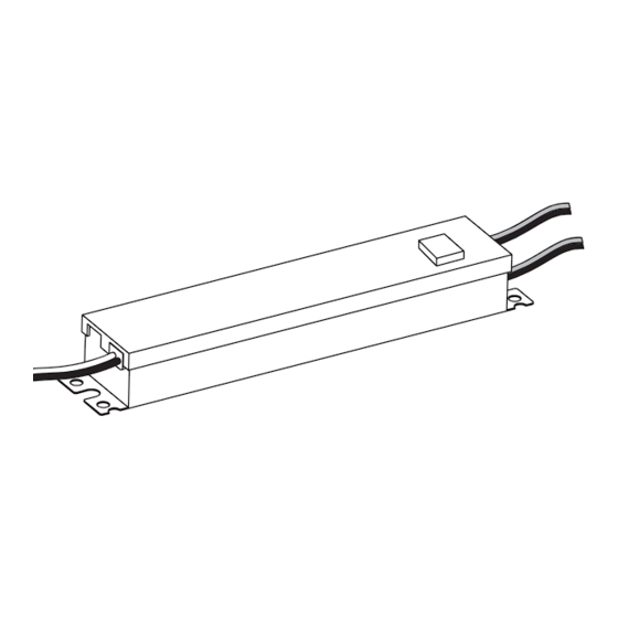
GECLPS5-2
LED Control Module Features
• LED Control Module for GECLPS5 and GECLPS6 retrofit
• UL: Class 2 input
BEFORE YOU BEGIN
Read these instructions completely and carefully.
RISK OF ELECTRIC SHOCK
• Disconnect power at fuse box or circuit breaker before servicing
or installing product.
• Properly ground Tetra
power supply.
®
RISK OF FIRE OR ELECTRIC SHOCK
• LED Retrofit Kit installation requires knowledge of sign electrical
systems. If not qualified, do not attempt installation. Contact a
qualified electrician.
• Install this kit only in host signs that have been identified in the
installation instructions and where the input rating of the retrofit kit
does not exceed the input rating of the sign.
• Installation of this LED retrofit kit may involve drilling or punching of
holes into the structure of the sign. Check for enclosed wiring and
components to avoid damage to wiring and electrical parts.
• Do not make or alter any open holes in an enclosure of wiring or
electrical components during kit installation.
RISK OF FIRE
• Use only approved wire for input/output connection. Minimum
size 18 AWG (0.82 mm
).
2
• Follow all local codes.
RISK INJURY
• While performing installations described, gloves, safety
glasses or goggles should be worn.
Prepare Electrical Wiring
Electrical Requirements
• Limited to use in dry and damp locations. The suitability of rain
enclosures shall be determined if intended for wet location.
• The grounding and bonding of the LED Driver shall be done in
accordance with National Electric Code (NEC) Article 600.
• Follow all National Electric Codes (NEC) and local codes.
• These products are only suitable for connection to a circuit
from a Class 2 power source.These products have not been
evaluated for use when connected to a power source that does
not comply with Class 2 voltage and energy limited supplies.
WARNING / AVERTISSEMENT
RISQUES DE DÉCHARGES ÉLECTRIQUES
• Coupez l'alimentation électrique à la boîte de fusibles ou au disjoncteur avant
l'entretien ou l'installation du produit.
• Assurez-vous de correctement mettre à terre le bloc d'alimentation Tetra
RISQUE D'INCENDIE OU DE CHOC ÉLECTRIQUE
• L'installation de l'équipement de remplacement DEL exige Ia connaissance
des systèmes électriques pour enseignes. Si non qualifié, ne tentez pas
d'installation. Veuillez contacter un électricien qualifié.
• Risque d'incendie ou de choc électrique. Installez cet ensemble seulement
dans des enseignes hôtes qui ont été identifiés dans les instructions
d'installation et dont la capacité d'entrée de l'ensemble ne dépasse pas la
capacité d'entrée de l'enseigne.
• L'installation de cet équipement de remplacement DEL peut impliquer le
perçage ou le poinçonnage de trous dans la structure du panneau Vérifiez
le câblage et les composants inclus pour éviter d'endommager le câblage
et les composants électriques.
• Ne pas faire ou modifier les trous ouverts dans une enceinte de câblage
ou de composants électriques pendant l'installation de cet équipement de
remplacement DEL.
RISQUES D'INCENDIE
• N'utilisez que des fils approuvés pour les entrées/sorties de connexion.
Taille minimum 18 AWG (0.82 mm
• Respectez tous les codes locaux.
CAUTION / ATTENTION
RISQUES DE BLESSURE
• Lors de l'exécution des installations décrites, des gants, des lunettes
de sécurité ou des lunettes de protection doivent être portées.
Save These Instructions
Use only in the manner intended by the manufacturer.
If you have any questions, contact the manufacturer.
Installation Guide
SIGN164 | GE2026-2818
).
2
RETROFIT SIGN CONVERSION LED KIT FOR USE ONLY IN
ACCORDANCE WITH KIT INSTRUCTIONS.
KIT IS COMPLETE ONLY WHEN ALL PARTS REQUIRED BY
THE INSTRUCTIONS ARE PRESENT.
TROUSSE DE CONVERSION À DEL POUR LA
MODERNISATION DES ENSEIGNES
À UTILISER CONFORMÉMENT AU GUIDE D'INSTALLATION.
24
24
Volt
.
®
Advertisement
Table of Contents

Subscribe to Our Youtube Channel
Related Manuals for Current Tetra GECLPS5-2


Summary of Contents for Current Tetra GECLPS5-2
- Page 1 Installation Guide SIGN164 | GE2026-2818 LED Control Module Volt GECLPS5-2 LED Control Module Features • LED Control Module for GECLPS5 and GECLPS6 retrofit • UL: Class 2 input BEFORE YOU BEGIN Read these instructions completely and carefully. WARNING / AVERTISSEMENT RISK OF ELECTRIC SHOCK RISQUES DE DÉCHARGES ÉLECTRIQUES •...
- Page 2 LED power supply will be within the voltage ratings of the new LED power supply, and have a current rating not exceeding 20A, or that permitted by applicable local, state, or country electrical codes (whichever is less).
- Page 3 Tetra LED Control Module GECLPS5-2 Installation Guide ® White to white or blue Green to To LED modules green Black to black Red (+) Red stripe (+) or brown Inline connector LED driver LED control module Cap unused leads AC line Black or blue (-) White (-) Wire AC line to LED driver(s) in...
- Page 4 Page 3 of 3 (Rev 11/28/23) © 2023 Current Lighting Solutions, LLC. All rights reserved. GE and the GE monogram are trademarks of the SIGN164 | GE2026-2818 General Electric Company and are used under license. Information provided is subject to change without...
Need help?
Do you have a question about the Tetra GECLPS5-2 and is the answer not in the manual?
Questions and answers