Sign In
Upload
Download
Add to my manuals
Delete from my manuals
Share
URL of this page:
HTML Link:
Bookmark this page
Add
Manual will be automatically added to "My Manuals"
Print this page
×
Bookmark added
×
Added to my manuals
Manuals
Brands
Aleko Manuals
Lawn and Garden Equipment
16x10
Installation & owner's manual
Aleko 16x10 Installation & Owner's Manual
Half cassette led awning manual
Hide thumbs
1
Table Of Contents
2
3
4
5
6
7
8
9
10
11
12
13
14
15
16
17
18
19
20
21
22
23
24
25
26
27
28
29
30
31
32
33
34
35
36
37
38
39
page
of
39
Go
/
39
Contents
Table of Contents
Bookmarks
Advertisement
Quick Links
1
Assembly Instructions
2
Wall Mounting Instructions
3
How to Pair Your Awning Remote and Set up Awning Limit Switch
Download this manual
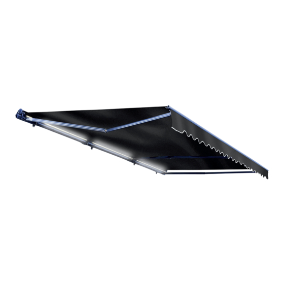
Half Cassette LED
Awning Manual
16x10 and 20x10-ft. Sizes
Installation & Owner's Manual
Table of
Contents
Previous
Page
Next
Page
1
2
3
4
5
Advertisement
Need help?
Do you have a question about the 16x10 and is the answer not in the manual?
Ask a question
Questions and answers
Related Manuals for Aleko 16x10
Lawn and Garden Equipment Aleko 20x10 Installation & Owner's Manual
Half cassette led awning manual (39 pages)
Lawn and Garden Equipment Aleko Victoria Series Installation Manual
Retractable awning (28 pages)
This manual is also suitable for:
20x10
Save PDF
Print
Rename the bookmark
Delete bookmark?
Delete from my manuals?
Login
Sign In
OR
Sign in with Facebook
Sign in with Google
Upload manual
Upload from disk
Upload from URL


Need help?
Do you have a question about the 16x10 and is the answer not in the manual?
Questions and answers