Table of Contents
Advertisement
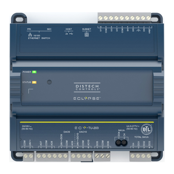
ECLYPSE™ ECY-TU-203 Connected
Terminal Unit Controller
Product Description
The ECLYPSE Connected Terminal Unit Controller (ECY-TU) is designed to control terminal units such as fan coil units, chilled beams, ceilings, and
heat pumps.
It integrates a control, automation and connectivity server, a power supply, and dedicated I/Os in one convenient package. Each model supports BAC-
net/IP communication and is listed as a BACnet Building Controller (B-BC) and feature wired and wireless advanced IP connectivity for efficient and reli-
able installation.
The ECY-TU comes with an embedded web server that enables web-based application configuration and an HTML5 visualization interface. It also fea-
tures embedded scheduling, alarming, and logging. Control logic and graphic user interface can be customized as required for the application.
Moreover, as part of the Smart Room Control solution, these controllers can control lighting fixtures (DALI, ON/OFF, dimming) and shades/sunblind mo-
tors (24 VDC or 100-240 VAC, up/down and angle rotation) through additional expansion modules.
General Installation Requirements
For proper installation and subsequent operation of each controller, pay special attention to the following recommendations:
£
Upon unpacking the product, inspect the contents of the carton for shipping damages. Do not install damaged modules.
£
Avoid areas where corroding, deteriorating, or explosive vapors, fumes or gases may be present.
£
Ensure the mounting surface can support the controller, DIN rail, and any user-supplied enclosure.
£
Allow for proper clearance around the controller's enclosure, and wiring terminals to provide easy access for hardware configuration and mainte-
nance, and to ventilate heat generated by the controller.
£
The controller's datasheet specifies the power consumption (amount of heat generated), the operating temperature range, and other environmental
conditions the controller is designed to operate under.
£
Ensure that all equipment is installed according to local, regional, and national regulations.
£
If the product is used and/or installed in a manner not specified by Distech Controls, the functionality and the protection provided by the product may
be impaired.
£
SELV (Separated Extra Low Voltage) inputs/outputs must be connected to other SELV equipment inputs/outputs.
£
PELV (Protective Extra Low Voltage) inputs/outputs must be connected to other PELV equipment inputs/outputs.
£
It is recommended that the controller(s) be kept at room temperature for at least 24 hours before installation to allow any condensation that may
have accumulated due to low temperature during shipping/storage to evaporate.
I n s t a l l a t i o n G u i d e
Advertisement
Table of Contents

Subscribe to Our Youtube Channel
Summary of Contents for Distech Controls ECLYPSE ECY-TU-203
- Page 1 Ensure that all equipment is installed according to local, regional, and national regulations. £ If the product is used and/or installed in a manner not specified by Distech Controls, the functionality and the protection provided by the product may be impaired.
- Page 2 UL-compliant installation requires the product to be installed in a certified electrical safety box. Any type of modification to any Distech Controls product will void the product’s warranty. Operating, handling, or servicing this product should be ensured by a qualified operator. Turn off the power before any kind of servicing.
-
Page 3: General Wiring Recommendations
General Wiring Recommendations Risk of Electric Shock: Turn off power before any kind of servicing to avoid electric shock. £ All wiring must comply with electrical wiring diagrams as well as national and local electrical codes. £ To connect the wiring to a device, use the terminal connectors. Use a small flat screwdriver to tighten the terminal connector screws once the wires have been inserted (strip length: 0.25’’... -
Page 4: Mounting Instructions
56.88 2.24 145.00 5.71 129.01 5.08 33.04 1.30 194.85 7.67 128.76 5.07 33.04 1.30 Front Front Profile Profile 7.99 0.31 7.99 0.31 Back Back Millimeters [Inches] Figure 2: Dimensions with terminal covers Mounting Instructions The controller can be mounted on a DIN rail for fast installation and easier maintenance. The controller also has four mounting holes to be mounted in a panel or on a wall. -
Page 5: Wall-Mounted Installation
DIN Rail-Mounted Installation 1. Securely mount the DIN rail horizontally on the wall. 2. Clip the controller onto the DIN rail. Figure 4: DIN-rail mounted controller 3. To detach the controller from the DIN rail, use a flat screw driver to pull down on the release clip located at the bottom center of the controller and pull it off the DIN rail, bottom first. -
Page 6: Power Wiring
Power Wiring Voltage 24 VAC; ±15%; Class 2 Maximum Consumption This is a Class 2 Product. Use a Class 2 transformer only (rated at 100 VA or less at 24 VAC) to power the controller(s). When calculating a controller’s power consumption to size the 24 VAC transformer, you must also add the external loads the controller is going to supply, including the power consumption of any connected subnet modules. -
Page 7: Input Wiring
Input Wiring Input options must be properly configured in EC- gfx Program to ensure correct input readings. For terminal block connector wiring best practices, see General Wiring Recommendations. Inputs can be connected as follows. Before connecting a sensor to the controller, refer to the installation guide of the equipment manufacturer. £... -
Page 8: Output Wiring
Output Wiring Output options must be properly configured in EC- gfx Program to ensure correct output values. The table below shows the available output wiring meth- ods. Outputs can be connected as follows. Before connecting an output device (actuator, relay, etc.) to the controller, refer to the datasheet and installation guide of the equipment manufacturer. - Page 9 Triac Outputs Triac outputs can be used to turn equipment and devices on and off (two-state outputs) and to control valve and damper actuators using Pulse Width Modulation (PWM). £ Triac output: 24 VAC (Max: 600 mA) £ To measure the state of a triac output, an external load must be connected. £...
- Page 10 Digital/Analog Outputs £ Digital Analog Outputs can be used as 24 VAC Triac outputs (using 24V~ / DOx pin) or as analog outputs (using AOx pin). £ 24V~ / DOx pin and AOx pin cannot be used simultaneously on the same Digital Analog output. £...
-
Page 11: Communications Wiring
IP addressing, radio path planning (when the ECLYPSE Wi-Fi Adapter is connected to the con- troller), etc. It can be downloaded from our website. For optimal performance, use Distech Controls category 5e network cable or refer to the ECLYPSE User Guide for cable specifications. -
Page 12: Configuring The Controller
Configuring the Controller Any of the following methods can be used to connect to the controller’s interface in order to configure it: £ Using the Xpress Network Utility £ Using the controller’s factory-default Hostname in the Web browser £ Using the controller’s IP address in the Web browser Using the Xpress Network Utility The Xpress Network Utility is a software application that runs on a PC that allows you to discover all ECY Series controllers connected to an IP network’s subnetwork or Wi-Fi network and to perform a range of operations on many controllers at once: you can set each controller’s Hostname and IP address,... - Page 13 Connecting to the Controller’s Configuration Web Interface At the first connection to an ECLYPSE Controller you will be forced to change the password to a strong password for the admin account to protect ac- cess to the controller. In Network Settings, configure the controller’s network parameters so that they are compatible with your network. See the ECLYPSE User Guide for more information about network settings and how to secure the controller.
-
Page 14: Using The Reset Button
All traveling cables permanently installed present an X type anchor. £ All cables must be able to operate above 176°F (80°C) £ This product is not repairable. If the device is physically malfunctioning or requires repair, it must be returned to Distech Controls. £ Pollution Degree 2 £... -
Page 15: Regular Maintenance
Cet appareil numérique de la Classe (B) respecte toutes les exigences du Règlement sur le matériel brouilleur du Canada. Specifications subject to change without notice. ECLYPSE, Distech Controls, the Distech Controls logo, EC-Net, Allure, and Allure UNITOUCH are trademarks of Distech Controls Inc. BACnet is a registered trademark of ASHRAE; BTL is a registered ®...
Need help?
Do you have a question about the ECLYPSE ECY-TU-203 and is the answer not in the manual?
Questions and answers