
Subscribe to Our Youtube Channel
Summary of Contents for LEF CT-4/D
- Page 1 CT-4/D CT-4/RS485 (MODBUS-RTU) CT-4/20MA (MODBUS-RTU 4-20 mA 0-20 mA) MANUALE DI INSTALLAZIONE ED USO INSTALLATION AND INSTRUCTIONS MANUAL...
-
Page 3: Caratteristiche Tecniche
ITALIANO CARATTERISTICHE TECNICHE Dimensioni • Contenitore 90X90X115 mm incluse morsettiere. • Pannello frontale 96x96 mm. • Peso 0.4 Kg. Alimentazione • Alimentazione universale (24÷240) Volt AC/DC ±10% 50/60 Hz senza rispetto della polarità, assorbimento massimo 4 VA. Ingressi • Quattro ingressi analogici, rilevamento e controllo della temperatura con sensori PT100 a tre fili nel range da -10 a +200 °C. - Page 4 ITALIANO • Controllo del ventilatore mediante isteresi con due valori di temperatura (H e L). • Cinque modalità di funzionamento selezionabili. • Riconoscimento sonde in avaria, massima flessibilità di gestione e semplicità di programmazione, controllo della validità dei dati introdotti in fase di programmazione.
-
Page 5: Collegamenti Elettrici
ITALIANO ALIMENTAZIONE La centralina può essere alimentata con (24÷240) Volt AC/DC ±10% 50-60 Hz senza rispetto di polarità. I morsetti di alimentazione sono indicati con la sigla AL1-AL2 e sono inoltre riportati in tabella TAB 1 alla fine del manuale. COLLEGAMENTI ELETTRICI Eseguire i collegamenti sulle morsettiere estraibili seguendo lo schema riportato in tabella TAB 1 alla fine del manuale. - Page 6 ITALIANO • Scala 4-20mA (-10°C 4mA - 200°C 20mA) • Formula di trasformazione: Iout = (T+10)/210*16 + 4 (corr. in mA temperature in °C) • Scala 0-20mA (-10°C 0mA - 200°C 20mA) • Formula di trasformazione: Iout = (T+10)/210*20 (corrente in mA temperature in °C).
- Page 7 ITALIANO Modificarla con i tasti UP/DOWN e confermare con ENTER. In caso di configurazione F=0 oppure F=2, la programmazione è terminata, diversamente proseguire come segue. Compare la lettera L per la scelta della temperatura minima al di sotto della quale il ventilatore si spegne, modificarla con i tasti UP/DOWN e confermare con ENTER.
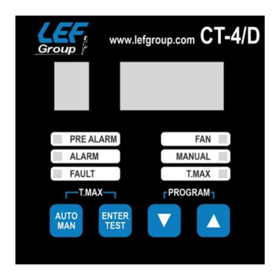
- Page 8 ITALIANO contemporaneamente i tasti AUTO/MANUAL e ENTER/TEST. La modalità di visualizzazione delle temperature massime é segnalata dall'accensione del led T. MAX posto sul pannello frontale. Si tenga presente che i valori massimi vengono azzerati ogni qualvolta si entra in fase di programmazione. Nel modo di funzionamento con ventilatore (F=1, F=3) lo stato del relè...
- Page 9 ITALIANO (CT-4/20MA) Successivamente appare la lettera d per la scelta dell’uscita del canale 4-20 mA - 0-20 mA e può assumere i seguenti valori: • d=1 uscita fissa temperatura canale 1 • d=2 uscita fissa temperatura canale 2 • d=3 uscita fissa temperatura canale 3 •...
-
Page 10: Norme Di Garanzia
ITALIANO MODALITA' DEGLI INTERVENTI Quando una delle sonde termometriche supera di 1 grado centigrado il valore prefissato dai limiti, dopo circa 1 secondo avviene la commutazione del relè e del diodo led corrispondente. Appena i valori di temperatura scendono di un grado centigrado sotto i valori impostati i relè... -
Page 11: Technical Features
-10 °C to +200 °C. Outputs • Four relays 250V AC, 10 A max (resistive load), free switch contact. • RS485 Half Duplex protocol MODBUS-RTU (CT-4/D). • RS485 Half Duplex protocol MODBUS-RTU - 4-20 mA - 0-20 mA galvanically isolated (CT-4/20MA). -
Page 12: Power Supply
ENGLISH • Detection of fault probes, maximum flexibility of managing and semplicity of programming, checking of validity of the insert data during programming phase. • Continuos storage of planned and reached values by each channel (limits and historic highs). • Dielectric isolation: 2.5 KV AC for 60”. •... -
Page 13: Electrical Connections
ENGLISH The power supply terminals are indicated with the abbreviation AL1-AL2 and are also shown in table TAB 1 at the end of the manual. ELECTRICAL CONNECTIONS Perform the connections on the terminal board following the scheme on TAB 1 at the end of this manual. - Page 14 ENGLISH • shielded, better if also stranded • With a section of not less than 0.5 mm PROGRAMMING Push and hold the buttons UP/DOWN for programming menù. On the display appears finally the letter F which allows to fasten the state of the monitor system: •...
- Page 15 ENGLISH temperature and the relative channel. Anyway, the necessary time for programming is checked. Over 1 minute from beginning of the programming phase, the same is interrupted and is not saved so the previous set limits remain active. The visualisation mode can be modified from manual to automatic system pressing the special button AUTO/MANUAL.
- Page 16 ENGLISH ADVANCED PROGRAMMING MENU Setting the parameter F = 4 is possible programming independent thresholds P, A, L, H for each channel. Appears in the word CH(n) with n. (1-4), using UP/DOWN you need to decide whether to make the channel active or not, and if so, are asked to introduce the thresholds P and A.
-
Page 17: Test Relays
ENGLISH (CT-4/20MA) Then the letter s appears to define the type of standard to be adopted • S1 mode 4-20 mA (default of monitor unit) • S2 mode 0-20 mA Below is the letter t which defines the scan time in seconds valid only in d = 6 mode •... -
Page 18: Warranty Rules
ENGLISH WARRANTY RULES The device has a warranty period time of 2 years from test date marked on the label and at the end of this manual. The warranty is valid only whether damages are due to manufacturing defects or to an incorrect calibration of the probes. - Page 19 TAB 1 - 19 -...
- Page 20 TAB 2 TYPE DATA RANGE READ ONLY Temperature channel 1 -1000 / +20000 READ ONLY Temperature channel 2 -1000 / +20000 READ ONLY Temperature channel 3 -1000 / +20000 READ ONLY Temperature channel 4 -1000 / +20000 READ ONLY Historical max temp. channel 1 -1000 / +20000 READ ONLY Historical max temp.
- Page 21 TAB 2 Fault not active Fault active • Register 10 Status relay channel Fan (bit 3) Fault (bit 2) Pre-alarm (bit 1) Alarm (bit 0) Relay not active Relay active • Register 21 Status channel CH1 to CH4: bit 0 to bit 3 Channel disable Channel enable •...
- Page 22 NOTES - 22 -...
- Page 23 - 23 -...
- Page 24 L.E.F. S.R.L. Viale L.Ariosto 478 - 50019 Sesto Fiorentino (FI) ITALY Tel (+39) 055 4217727 – Fax (+39) 055 4217719 - www.lefgroup.com...
Need help?
Do you have a question about the CT-4/D and is the answer not in the manual?
Questions and answers