Table of Contents
Advertisement
Quick Links
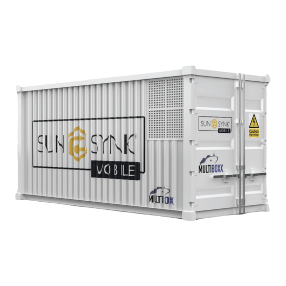
INNAGATOR
Power & energy storage system with 1MWh battery capacity
TECHNICAL PACK
Global Tech China Ltd, Units 702-704, 7/F Texwood Plaza,
6 How Ming Street, Kwun Tong, Kowloon, Hong Kong.
Tel: +852 2884 4318 Fax: +8522884 4816
www.sunsynk.com / sales@sunsynk.com
PLEASE RETAIN FOR
v.1 (07/06/23)
FUTURE REFERENCE
Advertisement
Table of Contents

Summary of Contents for SunSynk INNAGATOR
- Page 1 Power & energy storage system with 1MWh battery capacity TECHNICAL PACK Global Tech China Ltd, Units 702-704, 7/F Texwood Plaza, 6 How Ming Street, Kwun Tong, Kowloon, Hong Kong. Tel: +852 2884 4318 Fax: +8522884 4816 www.sunsynk.com / sales@sunsynk.com PLEASE RETAIN FOR v.1 (07/06/23) FUTURE REFERENCE...
-
Page 2: Table Of Contents
Fire System Working Logic Diagram Automatic Fire Alarm System 50kW INVERTER Pressure Relief Valve and Terminal Box Gas Fire Extinguishing System Design Safety Air Inlet and Exhaust Device General Safety Agent Release Control Panel Wiring Symbols/Safety Signs Safety Instructions Innagator | Technical Pack... - Page 3 Grid Supply Page Battery Module Installation in Rack Paralleling Inverters Advanced Settings 121 Startup Steps of HV Series Battery Connecting the DRM’s 12V Power Supply for HV Control Box Advanced Function Setup Display Solar Power Generated Home Screen Innagator | Technical Pack...
- Page 4 Maintenance and Upgrade Different Temperature (DT) Maintenance of HV Series Battery Other Faults (OF) USB's Upgrade Step Maintenance Interface Battery Module Storage Instructions for HVESS-Monitor Use Disposal Main Page Appendix Function List On-Grid System: 12V Supply Diagram Function Description Innagator | Technical Pack...
-
Page 5: Product Structure
PRODUCT STRUCTURE Innagator | Technical Pack... - Page 6 Innagator | Technical Pack...
- Page 7 Innagator | Technical Pack...
- Page 8 Innagator | Technical Pack...
- Page 9 Innagator | Technical Pack...
- Page 10 Innagator | Technical Pack...
- Page 11 Innagator | Technical Pack...
- Page 13 Innagator | Technical Pack...
-
Page 14: E20-Nngd-06D3 Specification
Quality Control: At SUNSYNK, a stringent quality control process is in place to monitor and evaluate ƒ every stage of container production. This includes regular inspections, testing, and compliance checks to ensure that all containers meet the specified standards. -
Page 15: Standards And Regulations
Marine: The container can be securely stacked up to seven (7) high in the ship cell guides of vessels, based on a maximum weight of 30,480kg. On the deck of vessels, the container can be stacked up to four (4) high and will be properly secured at the corner fittings using appropriate vertical and/or diagonal lashings. b. Road: The container can be transported on flat bed or skeletal chassis and will be secured at the bottom corner fittings using twist locks or equivalent mechanisms. c. Rail: The container can be transported on flat cars or special container cars and will be secured at the bottom corner fittings using twist locks or equivalent mechanisms. Innagator | Technical Pack... -
Page 16: Dimensions And Ratings
- 3/16" Front Door Opening Dimensions Dimensions Meters Feets +0 mm Width 1,818 m 5’ 11 9/16" -5 mm - 3/16" +0 mm Height 2,580 m 7’ 4 45/64" -5 mm - 3/16" Internal Cubic Capacity (Nominal) Meters Feets 30.2 cu.m 1,070 cu.ft Innagator | Technical Pack... -
Page 17: Ratings
Swing head hinges and lug T.S. : 441 N/mm Door hinge pins Stainless steel Door header pins Gasket retainers EPDM Door gasket t4.0 CHECK PLATE Floor board Y.P. – Min. Yield point T.S. – Min. Tensile strength Innagator | Technical Pack... -
Page 18: Construction
Under a load of 1.8 times the maximum gross weight, no part of the container will protrude more than 6.0 mm below the plane formed by the lower faces of the bottom corner fittings. This specification ensures that the container maintains its structural integrity and dimensional stability even under increased stress. These precise protrusion specifications guarantee the safe and efficient handling, stacking, and transporta- tion of the container, while ensuring compliance with industry standards. Innagator | Technical Pack... -
Page 19: Corner Fittings
Rear Corner Post: Each rear corner post is fabricated using a combination of components. The outer ƒ part consists of a 6.0 mm thick pressed steel section, while the inner part is made of a 40x113x12 mm Innagator | Technical Pack... -
Page 20: Door
Top Side Rail Each top side rail is made of a 80x60x3.0 mm thick rectangular tube, providing strength and stability to the container structure. Innagator | Technical Pack... -
Page 21: Side Wall
Zinc rich primer Zinc rich primer Exterior surface Total: 120 Epoxy primer Acrylic top coating Zinc rich primer Interior surface Total: 30 Zinc rich primer Zinc rich primer Under structure Zinc rich primer Total: 230 Bitumen Innagator | Technical Pack... -
Page 22: Markings
Through prototype testing, the container's performance, durability, structural integrity, and other essential factors will be thoroughly examined. This rigorous evaluation will help confirm that the container meets the necessary standards for safe and reliable operation. The manufacturer, in collaboration with the classification society, will analyze the test results to identify any areas for improvement or adjustments needed to meet the specified requirements. This iterative process ensures that the final container design achieves the desired performance and complies with all necessary regulations. By conducting prototype testing under the supervision of the classification society, the manufacturer demon- strates their commitment to delivering a high-quality product that meets the established industry standards and ensures the safe and efficient transport of goods. Innagator | Technical Pack... -
Page 23: Guarantee
The paint system applied to the container surface is guaranteed to be free from corrosion and failure for a period of three (3) years from the date of acceptance by the buyer. Corrosion is defined as rusting that exceeds RE3 (European Scale of degree of Rusting) on at least ten (10) percent of the total container surface, excluding damage resulting from impact or abrasion, contact with Innagator | Technical Pack... -
Page 24: Fire Alarm
Control panel spray indicator light on; When the maintenance switch is in the disconnected state, the release signal issued by the alarm controller will not start the FK-5-1-12 device. After the personnel on duty confirm the fire alarm, the maintenance switch will reach the connected position with the key, and then the system can be started, and the fire extin- guisher can be sprayed. Innagator | Technical Pack... - Page 25 The system shall be constructed and accepted in strict accordance with EN 15004-1-2019 and the de- ƒ sign and construction drawings approved by the fire control department. Install according to design drawings, equipment installation instructions, and on-site conditions; ƒ The bottle group of the fire extinguishable system should ensure the design size, firm fixation, conven- ƒ ient operation and observation, and beautiful appearance. Innagator | Technical Pack...
-
Page 26: Exhaust Ventilation System
Exhaust Ventilation System Innagator | Technical Pack... -
Page 27: Exhaust Ventilation System Layout
The H2 and CO gas detectors transmit an RS485 signal to the CC Room for supervisory purposes. ƒ The ventilation control unit box should be mounted 1.1 meters above the floor. ƒ NOTE: Air ventilation fan`s action signal will be transmitted to CC Room. ƒ Control panel will transmit operation signal of air inlet and outlet louver to CC Room. ƒ Innagator | Technical Pack... - Page 28 Innagator | Technical Pack...
-
Page 29: Technical Parameter Of
0.03 m Design Pressure 2.5 Mpa Ambient Temperature 20 °C Filling Capacity per Bottle 24 kg Design Dosage of Fire Extinguishing Agent 23.09 kg Amount of Fire Extinguishing Agent Stored 24 kg Number of Storage Containers Specifications for Storage Containers Innagator | Technical Pack... -
Page 30: Fire System Working Logic Diagram
When maintenance personnel enter the container, they should switch the alarm system to manual mode automatically. In manual mode, if a fire is detected by the detectors, the controller will activate only an audi- ble and visual alarm but will not start the gas fire extinguishing system. To initiate the gas fire extinguishing system, the personnel need to manually start it using the emergency start button. When personnel leave the container, they must switch the system back to automatic mode. Innagator | Technical Pack... -
Page 31: Automatic Fire Alarm System
Automatic Fire Alarm System Innagator | Technical Pack... -
Page 32: Pressure Relief Valve And Terminal Box
Pressure Relief Valve and Terminal Box Innagator | Technical Pack... -
Page 33: Gas Fire Extinguishing System Design
Manual Activation Button: In addition to automatic activation, the system features a clearly labeled and ƒ easily accessible manual activation button. This provides an option for individuals to initiate the fire extin- guishing process if needed, such as in case of a false alarm or when immediate action is required before the automatic mode activates. Mechanical emergency manual is included. ƒ Innagator | Technical Pack... - Page 34 Suitable Pipe Connections: For pipe connections, threaded connections are used when the nominal di- ƒ ameter is equal to or less than 80mm, ensuring a secure and reliable joint. For larger diameters exceed- ing 100mm, flange connections are employed. These connection methods provide robust and leak-free connections, maintaining the integrity of the system and facilitating easy maintenance and inspection. Innagator | Technical Pack...
- Page 35 Pressure Relief Port Size Calculation: The size of the pressure relief port in the protection zone can be ƒ determined using the DA formula: Fx = 0.15Qx / (Pf^0.5). Qx represents the average release rate of the fire extinguishing agent in the protected area, meas- ƒ ured in kilograms per second (kg/s). Pf denotes the allowed internal pressure that the enclosure can withstand, measured in Pascals (Pa). ƒ Innagator | Technical Pack...
- Page 36 Emergency Start and Stop Buttons: Placed next to the doors outside the protection zone, enabling ƒ immediate activation or deactivation of the fire control system. Deflated Indicator Light and Audible/Visual Alarm: Positioned above the door to indicate the activa- ƒ tion of the fire control system. Gas Extinguishing System Starting Modes: Automatic Startup: When a probe (smoke or temperature sense) detects a fire, an alarm bell sounds ƒ as an early warning, and access control is released. If both smoke and temperature probes detect a fire simultaneously, a sound and light alarm initiates. Air conditioning, new fans, and fire valves are shut off, and non-fire power supplies, such as lighting, are cut off. After a delay of 30 seconds, the corresponding active fire extinguishing agent bottle group is activated, driving the passive fire extinguishing agent bottle group (if present), and releasing the fire extinguishing agent. Innagator | Technical Pack...
- Page 37 This ensures adequate space for the pipe to pass through and allows for future maintenance or modifications. Bushing Length: The length of the bushing through the wall should be equal to the thickness of the wall. ƒ This provides a secure and flush fit between the pipe and the wall, maintaining the integrity of the fire barrier. Similarly, the length of the bushing through the floor should extend 50 mm above the floor level. This additional height helps accommodate any floor finishes or potential variations in the floor level. Fireproof Sealing: To maintain fire resistance and prevent the spread of fire or smoke, the gap between ƒ the pipe and the bushing/casing should be filled with a fireproof sealing material. This ensures that the penetration is effectively sealed, preventing the passage of flames, heat, or gases. The fireproof sealing material helps maintain the fire integrity of the wall or floor and ensures compliance with fire safety regulations. Innagator | Technical Pack...
-
Page 38: Air Inlet And Exhaust Device
23. 09 kg Cylinder Specs 2. 5MPa 30L Actual Cylinder Number Actual Ejection Concentration 5.9 % Filling Quantity 24 kg Discharge Time 10 s Smoking Time 10 min Relief Opening Area 0.03 m Air Inlet and Exhaust Device Innagator | Technical Pack... -
Page 39: Agent Release Control Panel Wiring
Agent Release Control Panel Wiring Innagator | Technical Pack... -
Page 40: Fire Suppression
FIRE SUPPRESSION Multiboxx Design Calculation Innagator | Technical Pack... -
Page 41: Multiboxx Base Info
Fire Group (Class) Fire Protection Typical/default Battery Storage V = 30 m3 131 g / m3 4000g 600–1,200 mJ/ Typical/default Control Room V = 7.5 m3 134 g / m3 500 g 600–1,200 mJ/ Additional Information The Salgrom-X Aerosol Extinguishing System offers comprehensive fire protection using a total flood meth- od. Below are some additional details regarding the system's specifications and conformity to relevant stand- ards and regulations. Innagator | Technical Pack... - Page 42 Other remarks Salgrom-x aerosol fire suppression system consist of: Aerosol fire suppression units. ƒ Control panel. ƒ Two fire detection zones (including multi-criteria detectors and temperature detectors). ƒ Installation wiring. ƒ Activation and line control modules. ƒ Warning sounder/beacons. ƒ Manual release point/system activation switch. ƒ Circuit disconnecting switch. ƒ Innagator | Technical Pack...
-
Page 43: Multiboxx Components Listing
AEROSOL GENERATOR (Type :SRM-X1000E) - Modular aerosol generator with heat activation. PYRALIS ACTIVATION MODULE (Type: SRM-Pyralis) - Monitoring and controlling unit that does not require any power source to trigger the aerosol units. Added security for transportation & situation when units and not powered. Innagator | Technical Pack... -
Page 44: Sample Installations
Sample Installations Innagator | Technical Pack... -
Page 45: Electric Drawings
CF54/100 CABLE TRAY 1 JB-Limit switch 行程开关翻线盒 JB-Limit switch 后 前 前 后 行程开关翻线盒 1751 1828 CF54/100 CABLE TRAY 4 CF54/100 CABLE TRAY 3 Water immersed leakage rope 漏水绳 1142 地沟线槽 20*20PVC线槽 Trunking 后 前 前 后 20*20PVC线槽 Trunking Innagator | Technical Pack... - Page 46 2020 1400 1400 941,14 Innagator | Technical Pack...
- Page 47 Innagator | Technical Pack...
- Page 48 Innagator | Technical Pack...
- Page 49 Innagator | Technical Pack...
- Page 50 Innagator | Technical Pack...
- Page 51 Innagator | Technical Pack...
-
Page 52: Hvac System
R410A Refrigerant Factory Charge 3600 g Throttle Type Electronic expansion valve Liquid Pipe Ф9.53 mm Pipe Connections Gas Pipe Ф19.1 mm Cooling -15~55 ºC Ambient Temp. Operation Range Heating -15~27 ºC Indoor temperature 27°C DB, 19°C WB; outdoor temperature 35°C DB; equivalent refrigerant piping length 7.5m with zero level difference;connect to Cassette type indoor unit. Indoor temperature 20°C DB; outdoor temperature 7°C DB, 6°C WB; equivalent refrigerant piping length 7.5m with zero level difference;connect to Cassette type indoor unit. Sound pressure level is measured at a position 1m in front of the unit and 1m above the floor in a semi-anechoic chamber. Innagator | Technical Pack... -
Page 53: Specifications - Ac Series
Ceiling mounted: Sound pressure level is measured 1m in front and 1m below the unit in a semi-anechoic chamber. Unit body dimensions given are the largest external dimensions of the unit, including hanger attachments Innagator | Technical Pack... -
Page 54: User Interface
USER INTERFACE To access the User Interface (UI) website, please visit the following link: https://zyludj.axshare.com/#id=mq4jv4&p=dashboard&sc=3 Dashboard Environment Info Innagator | Technical Pack... -
Page 55: Energy Storage System
Energy Storage System Innagator | Technical Pack... -
Page 56: Logo Placement
LOGO PLACEMENT Multiboxx Innagator | Technical Pack... -
Page 57: Standard
Standard Innagator | Technical Pack... -
Page 58: Technical Specification
Dimension (L x W x H,mm) 6058*2438*2896 mm (238.50*95.98*114.02 in) Weight Appr. 16500 kg IP Rating of Enclosure IP54 Seismic Parameter Zone 4 Noise @1m Distance ≤ 75 dB Operating Temperature Range(ºC) -20~60( >45ºC derating) Relative Humidity ≤95% (non condensing) Certification IEC62477,UN3536 Circuit Diagram Innagator | Technical Pack... -
Page 59: System Schematic Drawings
SYSTEM SCHEMATIC DRAWINGS Powerline Convergence System Sketch Innagator | Technical Pack... -
Page 60: Main Circuit (Pcs Cabinet)
Main Circuit (PCS Cabinet) Innagator | Technical Pack... -
Page 61: Auxiliary Power Circuit (Ac Cabinet)
Auxiliary Power Circuit (AC Cabinet) Innagator | Technical Pack... -
Page 62: Ups Power Supply Circuit (Ac Cabinet)
UPS Power Supply Circuit (AC Cabinet) Innagator | Technical Pack... -
Page 63: Control Circuit (Ac Cabinet)
Control Circuit (AC Cabinet) Innagator | Technical Pack... -
Page 64: Bms Communication
(NO) (NO) (NO) (NO) (Control Room)(Battery Room) 日期 2023/6/6 EPLAN EPLAN GmbH & Co. KG LC通讯、供电 校对 ADMINISTRATOR Basic project with identifier structure to GB standard 审核 GB_bas001 页数 修改 日期 姓名 原始项目 替换 替换人 页 Innagator | Technical Pack... -
Page 65: Lc_Di/Do
DIC7 Exhaust Fan Fire Exhaust Door-1 (NO) Spare DIC8 (Control Room) Door-2 (NO) DIC9 (Battery Room) (NO) DID10 Gas Low (NO) DID11 Gas High (NO) DID12 Water Spare DIE13 Spare DIE14 Spare DIE15 DIF16 DIF17 DIF18 Innagator | Technical Pack... -
Page 66: Terminal Block (Wiring Diagram)
Terminal Block (Wiring Diagram) Innagator | Technical Pack... -
Page 67: Communication Topology (Single Cluster)
Communication Topology (Single Cluster) BMS_CAN RS485 BMU_CAN BMU-1 BMU-2 BMU-12 Innagator | Technical Pack EPLAN EPLAN GmbH & Co. KG 通讯拓扑简图(单簇)... -
Page 68: Communication Topology (Single Stack)
Communication Topology (Single Stack) Innagator | Technical Pack... -
Page 69: Ot Terminal Specification
Copper Tube Terminal (XMK Type) Model XMK 300-12 Cable Size 300 mm (A.W.G 500) Max Current lmax = 690/785A Material Copper Plating Dimension 44 mm 43 mm 24 mm 24 mm 23.5 mm 13 mm 29.5 mm 87 mm Innagator | Technical Pack... -
Page 70: 50Kw Inverter
CE marking could be used. ONLY qualified personnel should install Keep the equipment well-ventilated. or perform maintenance work on the units. This product's batteries contain an ex- plosive, self-reactive material that could Warranty Void if Seal is Broken blow up when heated. Innagator | Technical Pack... - Page 71 Do not dispose the device, accesso- ries, and packaging with regular waste. Maximum Continuous Output Current, Follow local ordinances or contact the Output Frequency and Voltage, & AUX manufacturer for disposal guidance. (programmable AC output on battery SOC). Innagator | Technical Pack...
-
Page 72: Safety Instructions
WARNING HIGH LIFE RISK DUE TO FIRE OR ELECTROCUTION. Sunsynk Three-Phase Hybrid Inverter can only be installed by a qualified licensed electrical contractor. This is not a DIY product. This chapter contains important safety and operating instructions. Read and keep this manual for future ƒ... -
Page 73: Product Introduction
Product Introduction The Sunsynk Three-Phase Hybrid Inverter is a multifunctional inverter, combining functions of inverter, solar charger and battery charger to offer uninterruptible power support with portable size. Its comprehensive LCD display offers user configurable and easy accessible button operation such as battery charging, AC/so- lar charging, and acceptable input voltage based on different applications. This is a multifunctional inverter, combining functions of inverter, solar charger and battery charger to offer uninterruptible power support with portable size. Its comprehensive LCD display offers user configurable and easy accessible button oper- ation such as battery charging, AC/solar charging, and acceptable input voltage based on different applica- tions. System Overview 1. Inverter Indicators 7. Parallel Port 13. Grid 2. LCD Display 8. CAN Port 14. Function Port 3. -
Page 74: Product Size
Product Size Innagator | Technical Pack... -
Page 75: Features
Smart battery charger design for optimised battery protection; ƒ Limiting function installed to prevent excess power overflow to the grid; ƒ Isolation transformer design; ƒ APPLICATIONS Marine (vessel power management); ƒ Power shedding (home/office/factory); ƒ UPS (fuel-saving systems); ƒ Remote locations with solar and wind generators; ƒ Building sites; ƒ Telecommunication; ƒ Innagator | Technical Pack... -
Page 76: Basic System Architecture
Consult with your system integrator for other possible system architectures depending on your require- ments. This inverter can power all kinds of appliances in the home or one environment, including motor-type appli- ances such as refrigerators and air conditioners. Innagator | Technical Pack... -
Page 77: Technical Specifications
PV String Input Reverse Polarity Protection Integrated Insulation Resistor Detection Integrated Residual Current Monitoring Unit Integrated Output Over Current Protection Integrated Output Shorted Protection Integrated Output Over Voltage Protection DC Type II / AC Type III Battery Over Current Protection Fuses Innagator | Technical Pack... - Page 78 General Data Operating Temperature Range -40~60 ºC, >45 ºC Derating Cooling Intelligent air cooling Noise ≤45 dB Communication with BMS RS485; CAN Weight 80 Kg Size 527W×894H×294D mm Protection Degree IP65 Installation Style Wall-mounted Warranty 5 years Innagator | Technical Pack...
-
Page 79: Installation
Parallel communication cable L-type Hexagon wrench Meter (optional) Data Logger x1 Sensor Clamp x3 DC+/DC- Plug connec- Battery Plug connectors T-type wrench x1 Stainless steel mounting tors including metal accessories x4 screws M4*12 x2 terminal xN Innagator | Technical Pack... -
Page 80: Selecting The Mounting Area
1 metre away from any television or radio receiver. This will prevent TV reception interference or radio noise. This will prevent radio signal interference from external units that might interfere with the Wi-Fi or GSM monitoring. Innagator | Technical Pack... -
Page 81: Mounting The Inverter
Choose the recommended drill head (as shown below) to drill 4 holes on the wall, 62-70mm deep. 1. Use a proper hammer to fit the expansion bolt into the holes. 2. Carry the inverter and hold it, ensure the hanger aims at the expansion bolt, and fix the inverter on the wall. 3. Fasten the screw head of the expansion bolt to finish the mounting. 62-70mm [(2.44in) to (2,75in)] Innagator | Technical Pack... - Page 82 Inverter hanging plate installation Innagator | Technical Pack...
-
Page 83: Function Port Definition
Function Port Definition Innagator | Technical Pack... -
Page 84: Battery Connection
All wiring/connecting must be performed by qualified personnel. In addition, connecting the battery with a suitable cable is essential for safe and efficient operation of the system Please follow below steps to implement battery connection: 1. Pass the cable through the terminal: 2. Put on the rubber ring: Innagator | Technical Pack... - Page 85 To verify if the battery is communicating, access the Li BMS menu as detailed in section 5.13, 'Setting Up a Lithium Battery', and check whether the values are realistic. It is important that the charge and discharge limits on that page match the numbers expected for the number of connected batteries. Innagator | Technical Pack...
-
Page 86: Grid And Backup Load Connection
50KW model, the recommended AC breaker for the backup load is 180A. There are three terminal blocks marked as GRID, LOAD, and GEN. Please do not confuse input and output connections. External AC SPD is compulsory on all Sunsynk inverters. WARNING All wiring must be performed by qualified personnel. -
Page 87: Pv Connection
In addition, we request users install PV junction boxes with surge protection to protect the system from a lightning strike. External AC SPD is compulsory on all Sunsynk inverters. To avoid any malfunction, do not connect any PV modules with possible current leakage to the inverter. For example, grounded PV modules will cause current leakage to the inverter. -
Page 88: Pv Module Wiring
2. Switch the DC isolator OFF. 3. Assemble PV input connector to the inverter. 4. Use the MC4 connectors supplied by Sunsynk with the inverter. WARNING Before connection, please ensure the polarity of the output voltage of the PV array matches the DC+ and DC- symbols. - Page 89 DC switch should be off. This will prevent a high voltage from flowing to the inverter, thereby causing risk to persons conducting installation or maintenance. Innagator | Technical Pack...
-
Page 90: Connecting The Ct Coil
Connecting the CT Coil The CT coil is one of the most important parts of the Sunsynk inverter. This device reduces the power of the inverter to prevent feeding power to the grid. This feature is also known as “Zero Export”. -
Page 91: Meter Connection
Meter Connection CHNT Meter Innagator | Technical Pack... -
Page 92: Chnt Meter With Ct Coil
When the inverter is in the off-grid state, the N line needs to be connected to the earth. In the final installation, a breaker certified according to IEC 60947-1 and IEC 60947-2 shall be installed with the equipment. Innagator | Technical Pack... -
Page 93: Earth Connection (Mandatory)
Ground cable shall be connected to ground plate on grid side this prevents electric shock if the original pro- tective conductor fails. Model Wire size Cable (mm Torque value (max) 50kW 0 AWG 53.5 20.3Nm The conductor should be made of the same metal as the phase conductors. Innagator | Technical Pack... -
Page 94: Wiring System For Inverter
Wiring System for Inverter Innagator | Technical Pack... -
Page 95: Wiring Diagram
Wiring Diagram Innagator | Technical Pack... - Page 96 3. AC Breaker for grid SUN 25K-SG-EU: 240A AC breaker SUN 30K-SG-EU: 240A AC breaker SUN 40K-SG-EU: 240A AC breaker SUN 50K-SG-EU: 240A AC breaker 4. AC Breaker for home load Depends on household loads Grid Innagator | Technical Pack...
-
Page 97: Typical Application Of Diesel Generator
SUN 50K-SG-EU: 240A AC breaker 3. AC Breaker for Generator port SUN 29.9K-SG-EU: 240A AC breaker SUN 30K-SG-EU: 240A AC breaker SUN 35K-SG-EU: 240A AC breaker SUN 40K-SG-EU: 240A AC breaker SUN 50K-SG-EU: 240A AC breaker Innagator | Technical Pack... -
Page 98: Three-Phase Parallel Connection Diagram
SUN 40K-SG-EU: 200A DC breaker SUN 50K-SG-EU: 200A DC breaker 10. AC Breaker for home load Ground Depends on household loads Battery pack Backup Load L1L2L3 Home Load Arrow pointing to inverter Master inverter Slave Inverter Slave Inverter Grid Innagator | Technical Pack... -
Page 99: Operation
Inverter functioning normally Alarm Red LED solid light Fault Function buttons Function Key Description To exit the previous mode Increase the value of a setting Down Decrease the value of a setting Enter Confirm setting change (If not pressed each time the setting will not be saved) Innagator | Technical Pack... -
Page 100: Lcd Operation Flow Chart
Grid Page Grid Graph Inverter Page Battery Page BMS Page HOME PAGE Load Page Load Graph Basic Setting Battery Settings Grid Settings System Mode System Setup Advanced Settings Aux Load Settings Fault Codes Li BMS Settings Innagator | Technical Pack... -
Page 101: Status Page
This page shows the status of Load Power, Grid Power, Inverter Power, Battery, Solar Power 1 and Solar Pow- er 2. To access the Status page, click on the BATTERY or AC LOAD dial on the Home page. Innagator | Technical Pack... -
Page 102: System Flow Page
(programmable), the battery power is fed into the inverter. 3. The inverter can then supply power to the grid (export or no export), load, and auxiliary or smart load. 4. CT coil controls the export power. Innagator | Technical Pack... -
Page 103: Setup Page
Access the advanced settings such as Paralleling and Wind Turbine (press the ADVANCE icon). ƒ Access the auxiliary load/smart load settings (press the AUX LOAD icon) ƒ Access the fault code register (press the FAULT CODES icon). ƒ Set up Li BMS (press the LI BMS icon). ƒ Innagator | Technical Pack... -
Page 104: Basic Setup
How to change the name: Change the letters in each box by moving the arrows up and down and then select OK. This will change the name on the home screen. SOLAR/TURBINE AC load BATTERY IN/OUT MPPT. GRID. Battery Grid Innagator | Technical Pack... -
Page 105: Factory Reset And Lock Code
7777. System self-check: Allows the user to conduct a system diagnosis. After ticking this item, it needs input the password. The default password is 1234 Test mode (only for engineers): For engineers to conduct tests. Innagator | Technical Pack... -
Page 106: Battery Setup Page
Until the battery reaches a point where it can change normally. TEMPCO settings: The temperature coefficient is the error introduced by a change in temperature. ƒ NOTE: Recommended: AGM and Flooded: Ah battery size x 20% = Charge/Discharge amps. Lithium: Ah battery size x 50% = Charge/Discharge amps. Gel: follow manufacturer's instructions. Innagator | Technical Pack... -
Page 107: Generator & Battery Page
Equalization V: Equalizing charge/overcharge to remove sulfate crystals that build up on the plates over ƒ time on lead-acid batteries. Equalization V for an AGM battery is 58.80V. NOTE: Do not alter these settings too often on the same battery, as it may damage the battery. Innagator | Technical Pack... - Page 108 1Amp 12V. Below is a simple reference circuit of an auto-start system that can auto-start generators on a boat. (Sunsynk will be releasing a new OS E406 ( Auto-Start ) for better generator control).
-
Page 109: Battery Discharge Page
Battery Discharge Page To configure inverter’s shut-down settings, click on the BATTERY icon and then on ‘Shut Down’. Innagator | Technical Pack... - Page 110 Activating Shutdown causes the inverter to enter standby-mode. It does not entirely shut down the inverter. Total shutdown occurs at voltages below 19V. The voltage displayed on the Sunsynk Parity Inverter will vary depending on whether the inverter is charging or discharging the batteries.
-
Page 111: Setting Up A Lithium Battery
After installing a lithium battery, check the communications page by clicking on the ‘Li BMS’ icon to see if the BMS information is visible. Suppose some information is not displayed correctly (it should look like the diagram below), then there will be a communication error. Innagator | Technical Pack... - Page 112 NOTE: With some types of lithium batteries, the BMS cannot be controlled by the Sunsynk inverter. In this case, treat the battery as a lead-acid type and set the charging and discharging protocol following the battery manufacturer's specifications.
-
Page 113: Program Charge & Discharge Times
Zero Export + Limit To Load Only: The hybrid inverter will only provide power to the backup load connect- ed. The hybrid inverter will neither provide power to the home load nor sell power to the grid. The built-in CT will detect power flowing back to the grid and will reduce the power of the inverter only to supply the local load and charge the battery. Solar Backup Load On-Grid Home Load Grid Battery Innagator | Technical Pack... - Page 114 Set the unit to charge the battery from the grid or generator ticking ‘Grid’ or ‘Gen’ and set what times this ƒ needs to occur. Set the time to discharge the unit to the load or export to the grid by unticking ‘Grid’ and ‘Gen’. ƒ Innagator | Technical Pack...
- Page 115 ‘over-current’ fault occurs. 6. Tick this box if you wish to set the solar panels to give power to the ‘Load’. If you untick this box, the solar will send power to charge the batteries. Innagator | Technical Pack...
- Page 116 The power produced is supplying the ‘Non-Essential Load’ while the inverter is set at a maximum power of 8kW (Max Sell Power). The inverter is connected to the grid, but no export is performed. The unit allows small amounts of power to flow from the Grid (100W Zero Export Power) to prevent any back-flow. In this example, the solar PV is prioritised to supply the Load first and then subsequently, charge the battery. Innagator | Technical Pack...
-
Page 117: Grid Supply Page
IT system: For the IT grid system, the Line voltage (between any two lines in a three-phase circuit) is ƒ 230Vac. If your grid system is an IT system, please enable “IT system” and tick the “Grid level” as 133-3P, as the picture above shows. Innagator | Technical Pack... - Page 118 ƒ ƒ LV2: Level 2 undervoltage protection point; LF3: Level 3 under frequency protection point; ƒ ƒ LV3: Level 3 undervoltage protection point. 0.10s: Trip time. ƒ ƒ HF1: Level 1 over frequency protection point; ƒ Innagator | Technical Pack...
- Page 119 20% rated power. For example: V1=90%, Q1=44%. When the grid voltage reaches 90% times of the rated grid voltage, the inverter output power will output 44% reactive output power. For the detailed setup values, please follow the local grid code. Innagator | Technical Pack...
- Page 120 P(PF) mode. For the detailed setup values, please follow the local grid code. NOTE: Only when the grid voltage is equal to or higher than 1.05 times the rated grid voltage will the P(PF) mode take effect. Innagator | Technical Pack...
-
Page 121: Paralleling Inverters Advanced Settings
Set the phase in which the inverter will be paralleled. Set the Modbus SN for paralleling. The Sunsynk parity inverter can be wired standalone or where more power is required it can be connected in parallel either single or 3 phase configuration. The maximum number of inverters that can be paral- leled in a single phase utility grid is 16 and the maximum number that can be paralleled in a three phase utility grid is 15A. - Page 122 The grid input can also be connected in parallel. ƒ You cannot connect the Aux/Gen port in parallel because this causes a conflict between the gen- ƒ erator's frequency and the grid's frequency. Innagator | Technical Pack...
- Page 123 If you need further help please refer to the Sunsynk website where you will find training videos and Fre- quently Asked Questions www.sunsynk.com. Firmware prior installation is important to be updated and all inverters in parallel or three phase system must be the same. Common questions that occur when paralleling inverters: Q1: What is the sequence to install/connect/commission? First of all, leave the main supplies off. Next, connect all communication cables, set up all LCDs and then, last...
-
Page 124: Connecting The Drm's
This can be selected under advance settings. This can be selected under advance settings. 1. DRM 1/5 5. Ref 0 2. DRM 2/6 6. D Ground 3. DRM 3/7 7. Net J 4-7 4. DRM 4/8 8. Net J 4-7 Innagator | Technical Pack... -
Page 125: Advanced Function Setup
For more details, please refer to the left-side pic- Relay ture. Solar Power Generated This page shows the daily, monthly, yearly, and total solar power produced. Access this page by clicking on the ‘Solar/Turbine’ icon on the Home Page. Innagator | Technical Pack... -
Page 126: Grid Power
Grid Power This page shows the Daily / Monthly / Yearly and total grid power export or consumed. Access this page by clicking on the ‘Solar/Turbine’ icon on the home page. TOTAL TOTAL Innagator | Technical Pack... -
Page 127: Advanced Settings For Wind Turbines
This can cause the turbine to speed up dramatically, which can be very dangerous and usually happens suddenly. Thus, it is essential to use a self-breaking turbine. Voltage (V) Max. Current (A) Power (W) 23.33 3500 17.50 3500 14.00 3500 11.67 3500 8.75 3500 Innagator | Technical Pack... -
Page 128: Advanced Settings For Auxiliary Load
A nice feature of this page is that when the batteries are full and the inverter is still producing power from the solar PV or turbine, it is possible to direct the power generated to another load such as a water heater. Innagator | Technical Pack... - Page 129 AC couple on load side: Connecting the output of the on-grid inverter at the load port of the hybrid invert- er. In this the situation, the hybrid inverter will not be able to show the load power correctly. AC couple on grid side: This function is reserved. Innagator | Technical Pack...
- Page 130 (OFF), the system frequency will become the setting value (AC Couple Frz high), and the micro-inverter will stop working. Stop exporting power produced by the micro-inverter to the grid. NOTE: Innagator | Technical Pack Micro Inv Input OFF and On is valid for certain FW versions only.
-
Page 131: Operation Modes
Operation Modes Mode I: Basic Mode II: With Generator Innagator | Technical Pack... -
Page 132: Mode Iii: With Smart-Load
Mode III: With Smart-Load Mode IV: AC Couple Innagator | Technical Pack... -
Page 133: Fault Codes
4. Generally, it will disappear automatically when shows F13; 5. If it remains same, turn on DC and AC switches for one minute, then turn on the DC and AC switches; 6. Seek help from Sunsynk. Innagator | Technical Pack... - Page 134 1. Check the PV side cable ground connection; GFCI_Failure 2. Restart the system 2-3 times; 3. If the fault still existing, please contact Sunsynk. AC Slide over current fault. 1.Check if the backup load power is within the range of the Tz_Ac_Overcurr_Fault inverter.
- Page 135 3. Seek help from us, if can not go back to normal state. 1. Check the battery 2 terminal voltage is high; 2. Restart the inverter 2 times and restore the factory set- BAT2_VoltHigh_Fault tings; 3. Seek help from us, if can not go back to normal state. Innagator | Technical Pack...
- Page 136 2. 2. Check PV module cable connection and clear the fault. 3. 3. Seek help from us, if can not go back to normal state. Heat Sink temp is too high Heat sink high-temperature 1.Check if the working environment temperature is too high. failure 2.Turn off the inverter for 30 minutes and restart. Innagator | Technical Pack...
- Page 137 The inverters meet the main standards concerning safety and electromagnetic compatibility. Be- ƒ fore leaving the factory, all inverters undergo rigorous testing to ensure the inverter can operate reliably, as presented in Chapter 3, ‘Technical Specifications’. If you need further help please refer to the Sunsynk website where you will find training videos and frequent- ly asked questions www.sunsynk.com. Innagator | Technical Pack...
-
Page 138: Commissioning
Check the battery charge and discharge is within Check the battery BMS is the C rating of the battery. communicating with the Too high will damage the inverter battery Innagator | Technical Pack... -
Page 139: Gdfi Fault
The inverter is low maintenance. However, it is important that at least twice a year (for dusty environments this may need to be carried out weekly) all the cooling fans, air ducts are cleaned and dust free. Check if there are no fault codes and Lithium battery communication is correct. Weekly cleaning statement: Suggest micromesh filters as an available option, micro ants here are a real problem. Innagator | Technical Pack... - Page 140 Appendix A Definition of RJ45 Port Pin for BMS1 RS485 Pin 485_B 485_A GND_485 CAN_H1 CAN_L1 GND_485 485_A 485_B Definition of RJ45 Port Pin for BMS2 RS485 Pin 485_B 485_A GND_485 CAN_H2 CAN_L2 GND_485 485_A 485_B Definition of RJ45 Port Pin for Meter Meter-485 Pin Meter-485_B Meter-485_A GND_COM Meter-485_B Meter-485_A GND_COM Innagator | Technical Pack...
- Page 141 Definition of RJ45 Port Pin for RS485 RS485 Pin Modbus-485_B Modbus-485_A GND_485 GND_485 Modbus-485_A Modbus-485_B RS232 WIFI/RS232 D-GND 12Vdc Innagator | Technical Pack...
- Page 142 Appendix B Split Core Current Transformer (CT) dimension: (mm). ƒ Secondary output cable length is 4m. ƒ For more information, training videos, software upgrades, help line, forum please refer to http://www.sunsynk.com - Tech Support (Do not forget to register first on the website). Sunsynk @energysolutions sunsynkofficial Innagator | Technical Pack...
-
Page 143: High Voltage Battery
European Low incorrect handling. Voltage and EMC Directives. Risk of electric shock. Refer to the operating instructions. Innagator | Technical Pack... - Page 144 MPPT Input Current & Max PV ISC. Battery Discharge Power. 230V TEMPERATURE Protective Conductor Terminal or Earth 15.70 A Ground Terminal. Ambient, Min & Max. Net Weight in Kilograms. Single Phase. Inverter DC to AC. Three Phase. Innagator | Technical Pack...
-
Page 145: General Safety Information
The installation is carried out by personnel who did not receive relevant training or guidance. Failure to observe the warnings and safety information in this manual. If there are any questions, please contact Sunsynk support after service. WARNING Failure to comply with the safety information can lead to life-threatening situations. -
Page 146: Proper Use
Knowledge of handling lithium-ion batteries (transportation, storage, disposal, hazard source). ƒ Understanding and complying with this document and other applicable documents. ƒ Installation video of High Voltage Series Battery can be found at www.sunsynk.com or contact us via ƒ email: support@sunsynk.com Innagator | Technical Pack... -
Page 147: Safety
6. TIMELY DEBUGGING: It is essential to schedule a debugging session for the battery energy storage system within six months of its delivery. This step ensures that any potential issues or malfunc- tions are addressed promptly, minimizing the risk of accidents or performance degradation. Innagator | Technical Pack... -
Page 148: Transport To The End Customers
628 kg. It is recommended that 2-3 people collaborate to install the battery rack. Use lifting devices such as pulleys or carts for lighter parts, while ensuring that the case remains undamaged. Do not stack more than 8 battery modules. Check whether the delivery is complete. Innagator | Technical Pack... -
Page 149: Storage Positions For Packaged Goods
Adjust the height of the base and tighten the nut. ƒ Auxiliary Tools and Materials Required AID/Material Auxiliary tools/Materials 1. Assemble the battery racks and fix them on the wall or connect the Fastening materials (M4*12 two racks. M6*12 screws, M6*100 expan- 2. Assemble the battery modules and high-voltage control boxes, and sion screws, M6 nuts) fix them to the racks. Innagator | Technical Pack... -
Page 150: Description And Installation
Weight Total (12 battery modules, 1 rack) 628 Kg Weight of each battery module / battery rack 44 - 85 Kg The altitude of the Installation site ≤2000m Humidity 5%~85% (RH) Warranty Period 10 years Case protection grade IP20 Certification CE/IEC62619/UN38.3 Innagator | Technical Pack... -
Page 151: Description Of Rack
Description of Rack 102x2 103x2 104x1 105x1 101x2 106x4 107x3 108x95 109x1 Description Side Upper Cross beam Lower cross beam Lower diagonal beam Upper diagonal beam Base L-bracket M6*12 outer hexagon cross combination screw Hex key Innagator | Technical Pack... -
Page 152: Installation Of Rack
Installation of Rack 1. Connect the upper cross beams (102) and lower cross beams (103) with the two rack sides (102) using M6*12 external hexagonal cross combination screws (108) and a PHILIP2 # screwdriver. 201x1 Innagator | Technical Pack... - Page 153 M6*12 external hex combination cross screws (108) and a screwdriver. 201x1 4. Screw the base (106) to the rack bottom plate and secure it with a PHILIP2# screwdriver or by hand. 5. To fix the rack on the wall, use a PHILIP2# screwdriver to install the rack fastener at the M6 screw hole above the rack and fix it with M6*12 outer hexagon cross combination screws (108). Fix the other side of the rack with the wall using M6*100 expansion screws. To fix two racks together, install the rack fastener at the M6 screw hole above the rack, and fix them together with M6*12 outer hexagon cross combina- tion screws and M6 nuts. Innagator | Technical Pack...
-
Page 154: Description Of Battery Module
HV light indicator High-voltage hazard indicator (yellow) Front ALARM light indi- Battery system fault alarm indicator (red) Front cator PCS - Connection position of PCS negative pole (black) Front PCS+ Connection position of PCS positive pole (orange) Front Innagator | Technical Pack... -
Page 155: Description Of Battery Module In Rack
The negative power cord of the high-voltage control box Standard Standard connecting 140mm ground wire A (ground wire B for external connection of bat- cable A (connecting the tery rack is not provided) high-voltage control box) Innagator | Technical Pack... - Page 156 485A+ 485B- The following table presents the definition of the high-voltage control box interface PCS, IN, and OUT con- nection pins. All use the same pin number sequence shown in the next image: Pin No. BMS-BMU Port Definition Upper BMU Port Definition Lower BMU Port Definition BMU_CANL BMU_CANL BMU_CANL BMU_CANH BMU_CANH BMU_CANH Innagator | Technical Pack...
-
Page 157: Battery Module Installation In Rack
After connecting the battery cables, press the air switch button on the high-voltage control box to turn OFF to ON, and then press the START button. After the screen lights up, wait for about 8 seconds until the yellow HV light indicator comes on. (The specific working time is subject to the HV light indicator's lighting-up time.) Innagator | Technical Pack... -
Page 158: 12V Power Supply For Hv Control Box
System Click this icon to enter the system maintenance. maintenance icon Voltage Total battery voltage. Battery current, the positive value representing discharge, the negative value Current representing charge. Battery remaining energy. Total energy Accumulated discharging energy. Innagator | Technical Pack... -
Page 159: Fault Indication
Over Voltage Under Voltage Over Temperature Under Temperature Insulation failure, there is a risk of current leakage Over Current Other Faults Different Voltage Different Temperature System Maintenance Click the icon on screen to enter the maintenance system password confirmation interface. Enter the password and press the Confirm key to enter the main interface of system maintenance. The oper- ation shall be performed by a professional. Innagator | Technical Pack... -
Page 160: Main Screen
System information This screen shows the information about the High Voltage Series Battery system. Information like product se- ries, number of the BMS, the system status, parallel status, power status, battery life status, and sub status. Innagator | Technical Pack... -
Page 161: Volt/Temp Information
This screen shows statuses related to the relay. In addition, in this page you can clear the relay adhesion. Version information This page contains all the information about BMS, BMU, and Screen software and hardware versions. Innagator | Technical Pack... -
Page 162: Fault Pages
Fault Pages In "Home Screen" page, click on each Fault Indication to enter in the Fault Page related. Under Voltage (UV) This screen shows the faults related to the under voltage of the system. Over Voltage (OV) This screen shows the faults related to the over voltage of the system.. Innagator | Technical Pack... -
Page 163: Under Temperature (Ut)
This screen shows the faults related to the under temperature of the system. Over Temperature (OT) This screen shows the faults related to the over temperature of the system. Over Current (OC) This screen shows the faults related to the over current of the system. Innagator | Technical Pack... -
Page 164: Different Voltage (Dv)
Different Voltage (DV) This screen shows the faults related to the different voltage of the system. Different Temperature (DT) This screen shows the faults related to the different temperature of the system. Other Faults (OF) This screen shows the other faults of the system. Innagator | Technical Pack... -
Page 165: Maintenance Interface
For safety, please unplug the power cord of the positive and negative interfaces before maintenance. NOTE: When inserting the SD card, unplug the battery power cord and manually turn the air switch to the off position. Innagator | Technical Pack... -
Page 166: Instructions For Hvess-Monitor Use
Support display of a maximum of 50 parallel parallel devices devices information History data History data Not available temporarily History record Read history information stored in BMS History record History event Read history event information stored in BMS Innagator | Technical Pack... -
Page 167: Function Description
2. Insert the network cable into the PCS port, click the OPEN PCS CAN BUS button to start the INVERTER CAN communication, and click the button again to stop such communication. Basic Information The default mode is Factory Mode. To display detailed information, change to Debug Mode and click the Set button. Innagator | Technical Pack... - Page 168 01. To display other module information, switch to the desired module group number. After the communication is available, the specific cell number and temperature information will be displayed in real-time. The HVESS-Monitor displays different alarms. There are protection events and alarm events. Both types of events are displayed in the list. When an alarm event disappears, it will be removed from the list. Innagator | Technical Pack...
-
Page 169: Parallel Information
BMS Parameter Offline BMU Parameter Offline Firmware Offline Manufacture Offline Offline Offline Info Offline Offline TYPE USBCAN_E Offline Offline CLOSE INTER-CAN BUS Offline TYPE USBCAN1 OPEN PCS CAN BUS History Data This page is not available temporarily. Innagator | Technical Pack... -
Page 170: History Records
0.008 3.286 TYPE USBCAN_E 18:59:55 366.3 49.75 50.0 100.0 0.008 3.286 2022-08-10 0.008 3.286 CLOSE INTER-CAN BUS 2022-08-10 19:03:28 366.3 49.75 50.0 100.0 47/598 Stop Read All TYPE USBCAN1 Save DELETE ALL OPEN PCS CAN BUS Innagator | Technical Pack... -
Page 171: History Events
EncodeFinish Info 2022-09-14 08:22:22 PowerOff 2165-165-165 25:165:165 PowerOff 2022-08-11 16:24:14 CurrModuleFault Active TYPE USBCAN_E 2022-08-11 16:24:14 PowerOff 2022-08-11 16:24:14 ChgRelayAction CLOSE INTER-CAN BUS 75/75 Stop Read All TYPE USBCAN1 Save DELETE ALL OPEN PCS CAN BUS Innagator | Technical Pack... -
Page 172: Real-Time Data Storage: Hvess-Monitor
2022-09-15 10:38:35 365.1 365.1 547.4 Statistics 2022-09-15 10:38:37 365.1 365.1 547.4 History Data SETTINGS BMS Parameter BMU Parameter Firmware Manufacture Info TYPE USBCAN_E CLOSE INTER-CAN BUS TYPE USBCAN1 Recording Clear Stop Save OPEN PCS CAN BUS Innagator | Technical Pack... -
Page 173: Parameter
HISTORY Statistics History Data SETTINGS BMS Parameter BMU Parameter Firmware Manufacture Info TYPE USBCAN_E CLOSE INTER-CAN BUS TYPE USBCAN1 OPEN PCS CAN BUS Green: operation succeeded Red: operation failed Yellow: the data read out is inconsistent Innagator | Technical Pack... -
Page 174: Inter-Can Firmware Upgrade
Factory Mode. To display more details, change to Debug Mode and click the Set button. The number of read/set successes/failures is displayed in the lower right corner. Restart to automati- cally return to Factory Mode. Innagator | Technical Pack... -
Page 175: Cell Types
To All BMU Parameter 11957 Read Clear Power On Count Firmware Battery Type EVE 100Ah Read Manufacture To All Relay Adhesion Clear Info TYPE USBCAN_E CLOSE INTER-CAN BUS TYPE USBCAN1 OPEN PCS CAN BUS Cell Types Innagator | Technical Pack... -
Page 176: Inverter Information
Communication Error Count System Status CLOSE INTER-CAN BUS Acting Module Count System Error Level Max Charge Current(A) Cycle Count Max Discharge Current(A) Software Version TYPE USBCAN1 Manufacturer Name Serial No. Module ID Balance(01~08) OPEN PCS CAN BUS Innagator | Technical Pack... -
Page 177: Pcs Can Firmware Upgrade
BMS upgrade succeeds or not, it will continue to upgrade BMS at the next address. When the device address is filled in with a figure other than 1 (for example, 2), the HVESS-Monitor will only upgrade a single BMS whose address matches the input. The single BMU upgrade operation is similar. After the upgrade, an OK message will be displayed. Innagator | Technical Pack... -
Page 178: Fault Description
Exceeding the parameter set value and set time Insulation level 2 Exceeding the parameter set value and set time Exceeding the parameter set value and set time Heating film overtemperature alarm (>75°C, 2s) Exceeding the parameter set value and set time Heating film overtemperature protection (>80°C, 25) Innagator | Technical Pack... - Page 179 Pre-charge failure Pre-charge timeout Charging voltage too low The minimum cell voltage is lower than the set value BMU lost BMU message nor received for a long time The number of BMU address is different from the Abnormal number of BMU number of set parameters Innagator | Technical Pack...
-
Page 180: Fault Types Summary
Charge voltage level-2 too low Charge voltage too low pro- tection Total discharge voltage too Total discharge voltage too Total discharge voltage too low protection low alarm Cell undervoltage level-2 Cell undervoltage protection Cell undervoltage alarm alarm Innagator | Technical Pack... - Page 181 Internal total voltage acquisi- Internal total voltage acquisi- tion fault tion fault Current acquisition fault Current acquisition fault Limit protection Limit protection EEPROM failure EEPROM storage failure ISO EEPROM Insulation level-2 Insulation level-2 failure Innagator | Technical Pack...
-
Page 182: Maintenance And Upgrade
If the system is installed in a polluted environment, maintenance and cleaning must be carried out ƒ at short intervals. Clean the battery rack with a dry-cleaning cloth. Ensure that no moisture comes into contact with ƒ the battery connections. Do not use solvents. Innagator | Technical Pack... -
Page 183: Usb's Upgrade Step
2. To minimize self-discharge in a long storage period, disconnect the BATTERY connection (1/2) of the high-voltage control box of the DC connecting cable. This will interrupt the use of the 12 V power supply installed in the high-voltage control box and prevent the battery from self-discharging. Innagator | Technical Pack... -
Page 184: Disposal
2. Waste batteries may contain pollutants that can damage the environment or your health if im- properly stored or handled. 3. Batteries also contain iron, lithium and other important raw materials, which can be recycled. For more information, please visit www.sunsynk.com. Do not dispose of batteries as household waste! Innagator | Technical Pack... -
Page 185: Appendix
Appendix On-Grid System: 12V Supply Diagram Innagator | Technical Pack... - Page 186 Email us: sales@sunsynk.com Call us UK: +44 151 832 4300 VAT Number: 175669460 UK Address: Sunsynk, 17 Turnstone Business Park, Mulberry Avenue, Widnes, Cheshire, WA8 0WN. wered by Innagator | Technical Pack...
Need help?
Do you have a question about the INNAGATOR and is the answer not in the manual?
Questions and answers