Table of Contents
Advertisement
Advertisement
Table of Contents

Related Manuals for Hypertec CIARA ORION HF X210R-G6

Summary of Contents for Hypertec CIARA ORION HF X210R-G6
- Page 1 ORION HF X210R-G6 User Manual P a g e...
-
Page 2: About This User Manual
About this User Manual This user manual provides the information on Installation and maintenance of the Orion HF X210R-G6. Caution: Experienced technicians should perform the Installation and maintenance. Document title: ORION HF X210R-G6 Document number: Initial Release Document update date: July 2023 The following Notes, Cautions and Warnings might appear in this user manual. -
Page 3: Table Of Contents
Table of Contents Contents About this User Manual ..............................................2 Table of Contents ................................................3 ORION HF X210R-G6 Specifications ..........................................5 Chassis Overview ................................................ 6 Front Panel Components ............................................7 Back Panel Components ............................................. 7 Accessory Boxes & Rails .............................................. 8 Labelling .................................................. - Page 4 10.1 Building your PC system ..........................................29 10.1.1 CPU installation ..............................................29 10.1.2 Cooling system installation ..........................................30 10.1.3 Memory Installation ............................................31 10.1.4 SSD Installation ..............................................32 Chassis Cover Remove and Installation ........................................ 32 PCIe Device Installation............................................33 Rack Mounting ..............................................34 P a g e...
-
Page 5: Orion Hf X210R-G6 Specifications
ORION HF X210R-G6 Specifications The ORION HFX210R-G6 is a single socket, 1U rackmount form factor server and supports the following specification. Form Factor Chipset Intel® Z690 Processor Single Intel® Core™ i9-13900KS or i9-13900KF Overclocked up to 5.7GHz* *Maximum clock speed may vary depending on applications and workloads Cooling System High Performance Liquid Cooled System, Closed Loop and Maintenance Free Memory... -
Page 6: Chassis Overview
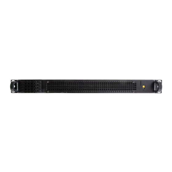
Chassis Overview The following illustrations are the Orion HF X210R-G6 chassis Front, Back and Side views. Front View Rear View P a g e... -
Page 7: Front Panel Components
Front Panel Components Rear Panel Components P a g e... -
Page 8: Accessory Boxes & Rails
Accessory Boxes & Rails The Orion HF x210R-G6 server includes (2) accessory boxes: Accessory Box #1 with Brackets and Screws* Accessory Box #2 with (2) Cables* The rails, bezel box and both accessory boxes are placed as shown below in the box with the server. * *ALL PICTURES SHOWN ARE FOR ILLUSTRATION PURPOSE ONLY.ACTUAL PRODUCT MAY VARY. -
Page 9: Labelling
Labelling This section provides information on the different labels found on the server. 6.1 HDD trays 6.2 System Serial Numbers and Model Number Labels 6.2.1 Front Panel 6.2.2 Rear IO Serial Number Model Number P a g e... -
Page 10: Rear Io
6.2.2 Rear Panel Serial Number (up) Model Number(down) 6.2.3 Inside Chassis HF X210R-G6 X210 10 | P a g e... -
Page 11: Support And Certification Labels
6.3 Support and Certification Labels X210 Orion HFX210R-G6 2023-06 X210 Orion HFX210R-G6 X210 Orion HFX210R-G6 11 | P a g e... -
Page 12: Chassis Layout
Chassis Layout The following illusration shows inside of the ORION HF X210R-G6 system. Front SSD Drive Bay Liquid Cooling Rear 12 | P a g e... -
Page 13: Detailed Motherboard Layout
Detailed Motherboard Layout Layout contents Page 1. CPU socket 2. DIMM slots 3. Expansion slots 4. Fan and Pump headers 5. Power connectors 6. M.2 Slot 7. SATA 6Gb/s port 8. USB 3.2 Gen 2x2 Type-C ® Front Panel connector 9. -
Page 14: Cpu Socket
8.1 CPU Socket The motherboard comes with a LGA1700 socket designed for 13 th Gen Intel ® Core™ & 12 th Gen Intel ® Core™, Pentium ® Gold and Celeron ® Processors. • Ensure that you install the correct CPU designed for LGA1700 socket only. DO NOT install a CPU designed for other sockets on the LGA1700 socket. •... -
Page 15: Dimm Slots
8.2 DIMM slots The motherboard comes with Dual Inline Memory Modules (DIMM) slots designed for DDR5 (Double Data Rate 5) memory modules. A DDR5 memory module is notched differently from a DDR, DDR2, DDR3, or DDR4 module. DO NOT install a DDR, DDR2, DDR3, or DDR4 memory module to the DDR5 slot. -
Page 16: Expansion Slots
8.3 Expansion slots Unplug the power cord before adding or removing expansion cards. Failure to do so may cause you physical injury and damage motherboard components. 16 | P a g e... -
Page 17: Fan And Pump Headers
8.4 Fan and Pump headers The Fan and Pump headers allow you to connect fans or pumps to cool the system. When an CIARA HYDRANODE fan is connected to a CIARA HYDRANODE fan connector, the CIARA HYDRANODE function will be available. •... -
Page 18: Power Connectors
8.5 Power connectors These Power connectors allow you to connect your motherboard to a power supply. The power supply plugs are designed to fit in only one orientation, find the proper orientation and push down firmly until the power supply plugs are fully inserted. Ensure to connect the 8-pin power plug, or connect both 8-pin power plugs. -
Page 19: Slot
8.6 M.2 slot The M.2 slot allows you to install M.2 devices such as M.2 SSD modules. • Intel® 13th & 12th Gen Processors: M.2_1 supports PCIE 4.0 x4 mode M Key design and type 2242 / 2260 / 2280 / 22110 storage devices. •... -
Page 20: Sata 6Gb/S Port
8.7 SATA 6Gb/s port The SATA 6Gb/s port allows you to connect SATA devices such as optical disc drives and hard disk drives via a SATA cable. • If you installed SATA storage devices to the SATA6G_1-4 ports, you can create a RAID 0, 1, 5, and 10 configuration with the Intel ® Rapid Storage Technology through the onboard Intel ®... -
Page 21: Usb 3.2 Gen 1 Header
8.9 USB 3.2 Gen 1 header The USB 3.2 Gen 1 header allows you to connect a USB 3.2 Gen 1 module for additional USB 3.2 Gen 1 ports. The USB 3.2 Gen 1 header provides data transfer speeds of up to 5 Gb/s. -
Page 22: Addressable Gen2 Header
8.11 Addressable Gen2 header The Addressable Gen2 header allows you to connect individually addressable RGB WS2812B LED strips or WS2812B based LED strips. The Addressable Gen2 header supports WS2812B addressable RGB LED strips (5V/ Data/Ground), with a maximum power rating of 3A (5V), and the addressable headers on this board can handle a combined maximum of 500 LEDs. -
Page 23: Mc Header
The Aura RGB header supports 5050 RGB multi-color LED strips (12V/G/R/B), with a maximum power rating of 3A (12V). Before you install or remove any component, ensure that the power supply is switched off or the power cord is detached from the power supply. Failure to do so may cause severe damage to the motherboard, peripherals, or components. -
Page 24: System Panel Header
8.15 System Panel header The System Panel header supports several chassis-mounted functions. • System Power LED header (PLED) The 2-pin and/or 3-1 pin headers allow you to connect the System Power LED. The System Power LED lights up when the system is connected to a power source, or when you turn on the system power, and blinks when the system is in sleep mode. -
Page 25: Thermal Sensor Header
8.16 Thermal Sensor header The Thermal Sensor header allows you to connect a sensor to monitor the temperature of the devices and the critical components inside the motherboard. Connect the thermal sensor and place it on the device or the motherboard’s component to detect its temperature. The thermal sensor is purchased separately. -
Page 26: Tpm Header
8.18 TPM header The TPM header allows you to connect a TPM module, which securely stores keys, digital certificates, passwords, and data. A TPM system also helps enhance network security, protect digital identities, and ensures platform integrity. The TPM module is purchased separately. 8.19 Q-LEDs The Q-LEDs check key components (CPU, DRAM, VGA, and booting devices) during the motherboard booting process. -
Page 27: 8-Pin Power Plug Led
8.20 8-pin Power Plug LED The 8-pin Power Plug LED lights up to indicate that the 8-pin power plug is not connected. 27 | P a g e... -
Page 28: Motherboard Block Diagram
Motherboard Block Diagram 28 | P a g e... -
Page 29: Basic Installation And Cabling
Basic Installation and Cabling 10.1 Building your PC system The diagrams in this section are for reference only. The motherboard layout may vary with models, but the installation steps are the same for all models. 10.1.1 CPU installation Ensure that you install the correct CPU designed for LGA1700 socket only. DO NOT install a CPU designed for LGA1155, LGA1156, LGA1151, and LGA1200 sockets •... -
Page 30: Cooling System Installation
10.1.2 Cooling system installation Apply Thermal Interface Material to the CPU cooling system and CPU before you install the cooling system, if necessary. Ensure to remove the CPU Socket lever protector on the lever latch before installing the cooling system, failure to do so may cause damages to your system. To install a CPU heatsink and fan assembly LGA1200 LGA1700... -
Page 31: Memory Installation
10.1.3 Memory Installation To remove a DIMM 31 | P a g e... -
Page 32: Ssd Installation
10.1.4 SSD Installation Chassis Cover Remove and Installation This section provides information on how to remove the chassis cover from the system. Step 1: Remove the screws anti-clockwise by using Philips screwdriver type 2. Step 2: Slide the Rear Top Cover towards the back of the system to release the cover. 32 | P a g e... -
Page 33: Pcie Device Installation
PCIe Device Installation 1. Lift up PCIe bracket latch 2. Pull out the card from PCIe slot 3. Remove the card 4. Repeat above procedure reversely for new card installation 33 | P a g e... -
Page 34: Rack Mounting
Rack Mounting This section provides information on how to mount a system into the rack with the rack rails. Step 1. Install rails into the rack 34 | P a g e... - Page 35 Step 2. Pull the inner and middle rails fully extended in lock position. Pull the white release button to slide out the inner rail. 35 | P a g e...
- Page 36 Step 3. Align the inner rail with the chassis mounting key, push and slide to lock. (The chassis shown below is only for reference) 36 | P a g e...
- Page 37 Step 4. Horizontally slide the chassis into the middle rail until click. 37 | P a g e...
- Page 38 Step 5. Pull/Push the blue release button on the inner rail to unlock the chassis and then push the chassis into rack. (The chassis shown below is only for reference) 38 | P a g e...
- Page 39 39 | P a g e...
Need help?
Do you have a question about the CIARA ORION HF X210R-G6 and is the answer not in the manual?
Questions and answers