Table of Contents
Advertisement
Quick Links
Advertisement
Table of Contents

Subscribe to Our Youtube Channel
Related Manuals for Moduspace MAX140 Plus


Summary of Contents for Moduspace MAX140 Plus
- Page 1 Bespoke Showcase Engineers MAX140 Plus Assembly Guide Version 3.0...
- Page 2 MAX140 Plus Assembly Guide Bars Bespoke Showcase Engineers Back Frame Back Frame Back Frame Front Frame Top Front Frame Bottom Front Frame Side Frame Front Frame Bottom Middle Bottom Middle Vertical Bar Vertical Bar x 2 Horizontal Bar x 2...
- Page 3 MAX140 Plus Assembly Guide Toolkit Bespoke Showcase Engineers Accessories for connecting display cases M4 Allen Horizontal Bracket x 4 M5 T-Handle Key x 1 Allen Key x 1 Front Panel Foot Pad x 4 Stacking Bracket x 4 Safety Screw x 1...
- Page 4 MAX140 Plus Assembly Guide Panels Bespoke Showcase Engineers Plexiglass Side Panel x 2 Plexiglass Front Panel x 1 Back Panel x 2 Top Panel x 2 Laminate Base x 1...
-
Page 5: Back Panel
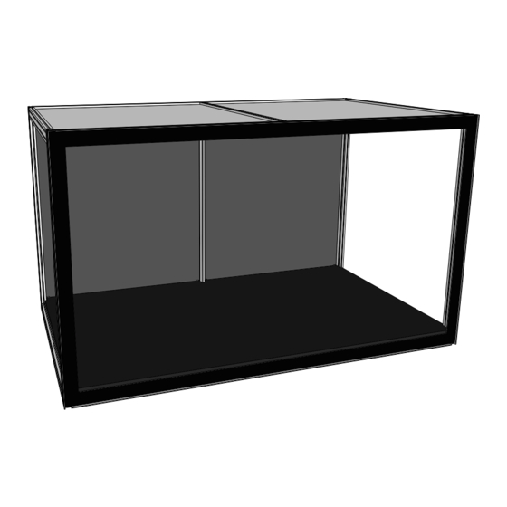
MAX140 Plus Assembly Guide Overview Bespoke Showcase Engineers Middle Top Horizontal Bar Magnet Safety Pilot Hole Front Frame Horizontal Bar Back Frame Horizontal Bar Side Frame Horizontal Bar Top Panel Top Panel Front Frame Front Frame Vertical Bar Vertical Bar... -
Page 6: Preparation Work
MAX140 Plus Assembly Guide Preparation Work Bespoke Showcase Engineers Steps to install C-Channel You will need You will need Step 1. Flatten one end of the C-Channel by pressing the open edges together. • Side Frame Horizontal Bar x 4 •... -
Page 7: Left Side Panel
MAX140 Plus Assembly Guide Left Side Panel Bespoke Showcase Engineers 15mm M5 Washer Step 4. Press down the Side Frame Horizontal Bar Step 2. into the Plexiglass Side Panel. Tighten the Slide in the Plexiglass Side Panel connecting screw using the T-Allen Key. -
Page 8: Right Side Panel
MAX140 Plus Assembly Guide Right Side Panel Bespoke Showcase Engineers 15mm M5 Washer Step 6. Step 8. Slide in the Plexiglass Side Panel Press down the Side Frame Horizontal Bar diagonally into the C-Channels of into the Plexiglass Side Panel. Tighten the the bars. -
Page 9: Base Frame
MAX140 Plus Assembly Guide Base Frame Bespoke Showcase Engineers Step 11. Connect Back Frame Horizontal Bar to Left Side Panel. Plexiglass Left Side Panel Step 10. Connect Back Frame Horizontal Bar to Left Side Panel. M5 Washer 15mm Step 9. - Page 10 MAX140 Plus Assembly Guide Back Panel Bespoke Showcase Engineers Step 12. Step 13. Slide in one Back Panel Slide in Back Frame Middle between the bars. Vertical Bar and position it to the pilot hole. Tighten the connecting screw using the T-Allen Key.
-
Page 11: Top Panel
MAX140 Plus Assembly Guide Top Panel Bespoke Showcase Engineers Please ensure the longer notch is facing the Back Panel. Step 17. Step 18. Step 19. Slide in a Top Panel Slide in a Middle Top Horizontal Slide in a Top Panel between the bars. - Page 12 MAX140 Plus Assembly Guide Top Panel Bespoke Showcase Engineers M5 Washer 15mm Please ensure the Front Frame Step 20. Vertical Bar Lip is on the right side of the panel before sliding it down. Slide in the Right Side Panel.
-
Page 13: Front Panel
MAX140 Plus Assembly Guide Front Panel Bespoke Showcase Engineers Step 22. Attach the Plexiglass Front Panel and insert Magnet Safety Pilot Hole the Safety Screw. Magnet Magnet Magnet Step 21. Tilt and insert the Laminate Base. Laminate Base...
Need help?
Do you have a question about the MAX140 Plus and is the answer not in the manual?
Questions and answers