Table of Contents
Advertisement
Quick Links
Advertisement
Table of Contents

Subscribe to Our Youtube Channel
Summary of Contents for JLCooper Electronics sBOX8D
- Page 1 GPI Control Panel for eBOX & gBOX User Manual...
- Page 2 JLCooper Electronics. All other brand names are the property of their respective owners. sBOX8D/sBOX8R User Manual, Second Edition Part Number 932131 ©2014 JLCooper Electronics, 142 Arena Street, El Segundo, CA 90245 USA phone (310) 322-9990 fax (310) 335-0110 www.jlcooper.com...
-
Page 3: Table Of Contents
................Rack Mounting ................Configuration ................eBOX ..................gBOX ..................Button Action ................Operation ................. Using the GPI Outputs ............Troubleshooting ..............Care and Service ..............Declaration of Conformity ............RoHS Statement of Compliance ..........JLCooper Electronics Limited Warranty ........ -
Page 4: Introduction
Introduction The sBOX8D and sBOX8R are companion products to the JLCooper eBOX and gBOX GPI Interfaces. The sBOX8D and sBOX8R connect to the eBOX and gBOX using an included expansion cable and provides a convenient user interface to trigger GPI outputs of an eBOX or gBOX. -
Page 5: Sbox Variations
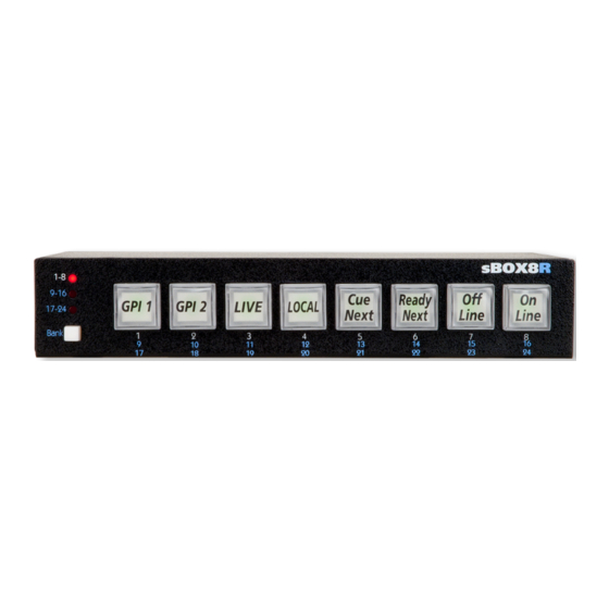
Variations The sBOX is available in two form factors, the sBOX8D which is the desktop version and the sBOX8R which is the rackmount version. The two different versions are shown below. sBOX8D - Desktop Version Note: The labels shown in the buttons are for illustrative purposes and are not included with the unit. -
Page 6: Installation
Installation eBOX Installation of the sBOX with an eBOX is straightforward. Simply connect the sBOX to the eBOX using the supplied cable as shown in the image below. Expansion eBOX 1 2 3 GPI Output Expansion Bank sBOX8 Connecting an eBOX to an sBOX8... -
Page 7: Gbox
gBOX Installation of the sBOX with the gBOX is just as straightforward. Simply connect the sBOX to the gBOX using the supplied cable as shown in the image below. Expansion gBOX GPI Output 1 2 3 Expansion Bank sBOX8 Connecting an gBOX to an sBOX8... -
Page 8: Multiple Sboxes
Multiple sBOXes Installation of multiple sBOXes with an eBOX or gBOX is similarly straightforward. Simply connect the sBOXes to the eBOX or gBOX in a “daisy chain” fashion using the supplied cables as shown in the image below. Expansion eBOX GPI Output 1 2 3 Expansion... -
Page 9: Rack Mounting
Rack Mounting The sBOX8R is designed to be mounted in a standard 19 inch rack. This can be accomplished by using the optional JLCooper Racktray. The part number for this item is JLC-RACKTRAY. Mounting the sBOX8R to the racktray is straightforward. Simply follow the directions below. -
Page 10: Configuration
Using the rear panel DIP switches, the sBOX can be configured to control a specific bank of 8 GPI Outputs. The following pictures below identify the location of the rear panel DIP switches. sBOX8D - Rear Panel sBOX8R - Rear Panel... -
Page 11: Ebox
eBOX The eBOX has 24 GPI Outputs. Using the sBOX, they are accessed in three banks of eight GPI Outputs. The following table shows the mapping of the sBOX buttons to the actual GPI Outputs in the various banks. sBOX Bank Bank Bank... - Page 12 The Bank Button on the front panel of the sBOX can determine the behavior of the large buttons on the sBOX. The sBOX allows switching between three banks of 8 GPI and Outputs using the Bank Button highlighted in the picture below. Using the rear panel DIP switches, the sBOX can be configured to control a specific bank of 8 GPI Outputs.
-
Page 13: Gbox
gBOX The gBOX has 48 GPI Outputs. Using the sBOX, they are accessed in six banks of eight GPI Outputs. The following table shows the mapping of the sBOX buttons to the actual GPI Outputs in the various banks. sBOX Bank Bank Bank... - Page 14 The Bank Button on the front panel of the sBOX can determine the behavior of the large buttons on the sBOX. By default, the sBOX GPI Outputs can be selected by the Bank button on the left side of the front panel. Using the rear panel DIP switches, the sBOX can be configured to control a specific bank of 8 GPI Outputs.
-
Page 15: Button Action
Button Action The behavior of the GPI Buttons can be configured to act as a momentary switch or toggle switch. To change the behavior of the GPI Buttons, simply press and hold the Bank Button for 3 seconds. The GPI Buttons will indicate their behavior by the state of the LEDs. -
Page 16: Operation
Operation Using the sBOX is straightforward. 1. If Bank switching is enabled, simply press the Bank Button until the desired bank of GPI Outputs is selected and, 2. Press the desired GPI Button to change the state of the GPI Output. -
Page 17: Using The Gpi Outputs
Using the GPI Outputs The sBOX has a 9 pin D-Subminiature connector that has 8 GPI outputs. These outputs mirror the state of switch LEDs 1-8 on the front panel. The outputs are CMOS outputs. GPI Output sBOX Function Ground sBOX GPI 1 sBOX GPI 2 sBOX GPI 3... - Page 18 The outputs of the sBOX GPI ports are CMOS. The output signal is referenced to pin 1 of the GPI Output Port. The GPI Outputs deliver 0 or +5 volts and are rated to +/- 6mA. 74HC374 Detail of GPI Output Note: Because the outputs are CMOS, the output voltage MUST be limited to voltage levels between 0 and 5 volts.
-
Page 19: Troubleshooting
Clean with a soft, damp cloth. Do not allow liquids, dust or other foreign matter to get inside the unit. There are no user-serviceable parts in the sBOX8. Please refer to the JLCooper Electronics Limited Factory Warranty on the last page for detailed warranty and service information. -
Page 20: Declaration Of Conformity
JLCooper Electronics Limited Warranty JLCooper Electronics ("JLCooper") warrants this product to be free of defects in materials or workmanship for a period of 12 months from the date of purchase. This warranty is non- transferable and the benefits apply only to the original owner. Proof of purchase in the form of an itemized sales receipt is required for warranty coverage.
Need help?
Do you have a question about the sBOX8D and is the answer not in the manual?
Questions and answers