Table of Contents
Advertisement
Quick Links
Advertisement
Table of Contents

Related Manuals for LS tractor LS3150-A

Summary of Contents for LS tractor LS3150-A
- Page 1 " " SERIAL NO. 21217580 AND UP OM 0421SB-A 01/15...
-
Page 3: Table Of Contents
TABLE OF CONTENT SPECIFICATIONS ..........................3 INTRODUCTION -TO THE PURCHASER ..................... 4 SAFETY PRECAUTIONS ........................5 Before Operation ..........................5 Notice ............................. 6 The Snowblower ..........................6 Before Operation ........................6 Snowblower Operation ....................7 The Tractor ............................. 8 General Information ......................8 Operating the Tractor ...................... - Page 4 TABLE OF CONTENT OPERATION ............................17 General Preparation ........................17 Operating Controls ........................17 Engine Speed ......................17 Up and Down Control ....................17 Increasing Traction and Stability ................. 17 Engaging the Drive Mechanism .................. 17 Deflector Adjustment ....................18 Skid Shoe Adjustment ....................
-
Page 5: Specifications
SPECIFICATIONS LS3150 Features and Specifications Input rotation (from driver's seat) Clockwise Overall width 50" Overall height (without chute) 21" Overall height (with chute) 45 1/4" Overall length (without female hitch) 22 1/2" Overall length (with female hitch) 30 3/4" Cutting width 49 3/4"... -
Page 6: Introduction -To The Purchaser
INTRODUCTION O THE URCHASER All products are designed to give safe, Illustrations dependable service if they are operated and illustrations necessarily maintained according to instructions. Read reproduce the full detail and the exact shape of understand this manual before the parts or depict the actual models, but are operation. -
Page 7: Safety Precautions
SAFETY PRECAUTIONS SAFETY FIRST This symbol, the industry's "Safety Alert Symbol", is used throughout this manual and on labels on the machine itself to warn of the possibility of personal injury. Read these instructions carefully. It is essential that you read the instructions and safety regulations before you attempt to assemble or use this unit. -
Page 8: Notice
SAFETY PRECAUTIONS OTICE A safe operator is the best assurance against accidents. All operators, no matter how experienced they may be, should read this operator's manual and all other related manuals before attempting to operate the equipment. Please read the following section and pay particular attention to all safety recommendations contained in this manual and those labeled on the equipment and on the tractor. -
Page 9: Snowblower Operation
SAFETY PRECAUTIONS NOWBLOWER PERATION 1. Before leaving the tractor unattended, take 10. If snowblower starts vibrate possible precautions. Park abnormally, disengage the PTO, stop the tractor/snowblower on level ground, place engine immediately and check for cause. the transmission in neutral, set the parking Excessive vibration is generally a sign of brake, disengage the PTO, lower the trouble. -
Page 10: The Tractor
SAFETY PRECAUTIONS RACTOR General Information 1. Read the operator's manual carefully 11. Use of rear counterweights for better before using tractor. Lack of operating traction and stability is recommended. knowledge can lead to accidents. 12. Handle fuel with care, as it is highly 2. -
Page 11: During Operation
SAFETY PRECAUTIONS During Operation 1. Do allow passengers 14. Keep all shields and covers in place. All tractor/snowblower at any time. There is no tractor and equipment shields and covers safe place passengers this must be correctly installed at all times. equipment. -
Page 12: Maintenance
SAFETY PRECAUTIONS AINTENANCE ALWAYS USE GENUINE PARTS WHEN 10. Do not modify or alter this equipment or REPLACEMENT PARTS ARE REQUIRED components operating functions. If you have questions concerning 1. Keep the tractor and snowblower properly modifications, consult with your dealer. maintained. -
Page 13: Transporting
SAFETY PRECAUTIONS RANSPORT TORAGE Before storing the snowblower, certain 1. When driving the tractor and equipment on precautions should be taken to protect it the road or highway under 25 mph, at night from deterioration. or during the day, use flashing amber warning lights and the Slow Moving 1. -
Page 14: Decals
DECALS Replace Immediately if Damaged LS TRACTOR 2500879 657761 657762 660988 LS3150 2500880 655683 657763 657346 657804 OM 0421SB-A... -
Page 15: Assembly
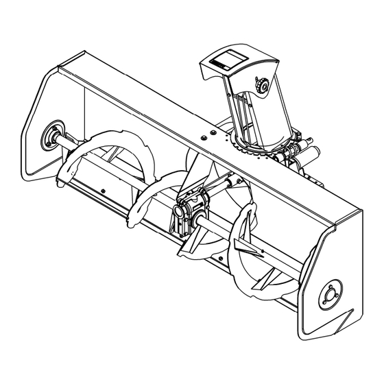
ASSEMBLY NOWBLOWER SSEMBLY The snowblower is pre-assembled at the factory, however, parts in the bag and box must be assembled. Use the present manual and lay out all parts for assembly. Separate bolts and nuts into various sizes. After assembly, torque all the bolts according to the "Torque Specification Table" enclosed at the end of the manual. -
Page 16: Attaching Snowblower To Quick Hitch
ASSEMBLY Attaching Snowblower to Tractor (Figure 2) 1. Move quick hitch lever (item 8) rearward to unlock position. CAUTION: 2. Install the male driveline (item 2), supplied To avoid serious personal injuries: with the drive kit, on snowblower female Make sure that the driveline quick driveline (item 3) and support with the driveline coupler is securely locked in place. -
Page 17: Installation Of Manual Rotation
ASSEMBLY Installation of Manual Rotation (Figure 3) 1. Install handle support (item 1) 4. Install the plastic handle (item 11) on the illustrated, with two M8 x 35mm hex. bolts rotation handle (item 12) and tighten all (item 2), 8mm lockwashers (item 3) and bolts. -
Page 18: Removing Snowblower From Tractor
ASSEMBLY Removing Snowblower from Tractor (Figures 3-4) 1. Park tractor/snowblower on level ground, place all control levers in neutral, set the parking brake, shut off the engine and remove the ignition key. 2. Figure 3: Remove the rotation handle (item 12) from the handle support (item 1) 3. -
Page 19: Operation
OPERATION ENERAL REPARATION PERATING ONTROLS 1. Read the operator's manual carefully Engine Speed before using the tractor and snowblower. 1. Start the tractor engine. Let the engine Be thoroughly familiar with the controls and warm up at least one minute before proper use of the equipment. -
Page 20: Deflector Adjustment
OPERATION Skid Shoe Adjustment WARNING (Figure 5) To avoid serious personal injury: 1. Adjust the snowblower so that the skid ake sure tractor engine and snowblower shoes run level and according to the come to a complete stop and tractor drive surface conditions so that stones are not mechanism is disengaged BEFORE making thrown with the snow. -
Page 21: Snow Removal Methods
OPERATION EMOVAL ETHODS When removing snow, do not use the snowblower as a dozer blade to push snow. Let the snowblower work its way through deep drifts. If the speed of your tractor is too fast, the snowblower may become overloaded and clog. -
Page 22: Maintenance
MAINTENANCE AINTENANCE ALWAYS USE GENUINE PARTS WHEN REPLACEMENT PARTS ARE REQUIRED Shear Bolts WARNING 1. Always use a special grade 5 shear bolt, To avoid serious personal injury: (656053) on fan and special grade 5 two grooved shear bolts (657295) on the •... -
Page 23: Lubrication
MAINTENANCE UBRICATION Use a good grease gun and lubricate as follows: DESCRIPTION INTERVAL LUBRICATION REQUIRED 8 hours Grease each universal joint Driveline Separate the sliding parts and cover each one of 24 hours them with grease 4 hours Driving chain and after each Lubricate with chain saw lubricant operation... -
Page 24: Parts
PARTS NTRODUCTION All parts are illustrated in "exploded views" which show the individual parts in their normal relationship to each other. Reference nums are used in the illustrations. These nums correspond to those in the "Reference Num" (REF) column, and are followed by the description and quantity required. O/L - "Obtain Locally"... -
Page 25: Chute Assembly
PARTS HUTE SSEMBLY ESCRIPTION Chute assembly inc. items 2 to 5 and decals 668633 Knob 5/16"NC 657309 Flat washer nylon 11/32" dia. hole 658467 Carriage bolt 5/16"NC x 1" gr.5 PTD 0300003 Flat washer nylon 7/16" dia. hole 658468 Hand guard 657308 Bolt hex. -
Page 26: Snowblower Assembly
PARTS NOWBLOWER SSEMBLY OM 0421SB-A... - Page 27 PARTS NOWBLOWER SSEMBLY ESCRIPTION Housing 669683 Gearbox (cw) 4500035 Seal kit 665775 Fan assembly including bushings 4300055 657327 Bushing (Oilite) 4300055 Skid shoes 669674 Carriage bolt 5/16" NC x 1" gr. 5, PTD 0300003 Key woodruff 655967 Lockwasher 5/16", PTD 1200003 Nut hex.
-
Page 28: Reduction Box
PARTS EDUCTION ESCRIPTION Reduction box ass'y incl. bearing & sprocket 657419 Reduction box 657355 Drive shaft with sprocket (H40C12) 657251 Bearing 1" with setscrew 665494 Triangular flange 656589 Carriage bolt 5/16" NC x 5/8" gr.5 PTD 0300001 Lockwasher 5/16" PTD 1200003 Nut hex. -
Page 29: Manual Chute Rotation
PARTS ANUAL HUTE OTATION ESCRIPTION Rotation support 657329 Handle support bracket 669965 Handle ass'y 667014 Rotation tube 665038 Rotation tube ass'y (includes 4-8-9-10) 665041 Rotation worm cw 657331 Plastic bushing 1 5/16" 657335 Hairpin 3mm x 65mm PTD 1800004 Universal block 658193 Rotation yoke 659595... -
Page 30: Worm Gearbox
PARTS EARBOX ESCRIPTION Gear box assembly 4500035 Casing kit (items 1 and 2) 4500021 Left casing ------ Right casing ------ Worm and gear kit (items 3 and 4) Not available Gear ------ Worm ------ Driving shaft 4500036 Bearing 661147 Bearing 663234 Seal kit (items 8 and 9) 665775... -
Page 31: Driveline Female Half
PARTS RIVELINE EMALE ESCRIPTION Driveline female half ass'y 4700044 Inner shield 658511 Nylon repair kit 661555 Yoke & female shaft ass'y 4700071 Universal joint kit 4700066 Yoke 1" dia.hole. 4700072 OM 0421SB-A... -
Page 32: Torque Specification Table
TORQUE SPECIFICATION TABLE ENERAL SPECIFICATION TABLE SE THE FOLLOWING TORQUES WHEN SPECIAL TORQUES ARE NOT GIVEN Note:These values apply fasteners as received from supplier dry, or when lubricated with normal engine oil. They do not apply if special graphited or moly sidulphide greases or other extreme pressure lubricants are used. These values apply to dry conditions;... - Page 36 Printed in Canada...
Need help?
Do you have a question about the LS3150-A and is the answer not in the manual?
Questions and answers