Table of Contents
Advertisement
Quick Links
Advertisement
Table of Contents

Related Manuals for CanadianSolar EP CUBE


Summary of Contents for CanadianSolar EP CUBE
- Page 1 Installation Manual V2.1 Page.1...
-
Page 2: Table Of Contents
5.9 Maintenance and Replacement..............................14 PRODUCT DESCRIPTION....................................15 1. Appearance........................................15 1.1 EP Cube HES......................................15 A. EP Cube PCS..................................... 16 B. EP Cube Battery Module................................17 C. EP Cube Base....................................17 D. EP Cube AC Switch Box................................. 18 Page.2... - Page 3 1. System Topology………..................................... 44 WIRING & COMMISSIONING...................................46 1. EP Cube system wiring..................................46 1.1. Wiring from Solar Panels to EP Cube PCS ..........................47 1.2. AC Wiring from EP Cube PCS to AC Switch Box........................49 1.3. Wiring of Other Components................................. 54 2.
-
Page 4: About This Manual
➢ Retain this manual for reference purposes. ➢ 1.1. Applicable Products This manual is valid for the EP Cube HES Series Only. EP Cube HES series includes following products: EP Cube HES-EU1-706G; EP Cube HES-EU1-710G; EP Cube HES-EU1-713G; EP Cube HES-EU1-716G;... -
Page 5: Copyright
1.6. Declaration of Conformity EP Cube system described in this manual complies with the applicable European directives. The certificate of compliance and completed certifications can be found in the download section of EP Cube website: https://eternalplanetenergy.com/EN/manuals.html... -
Page 6: Contact Us
1.8. Contact Us Eternalplanet Energy Co. Ltd Service Hotline: +49 89 51996890 Email: service.es@epcube.com, (For Spain only) Email: service.it@epcube.com , (For Italy only) Email: service.de@epcube.com , (For Germany only) Page.6... -
Page 7: Safety Instructions
In the case of irritation of the skin, eyes or mucous membranes, consult a doctor. 3. Contact the fire department. 4. Contact the EP service team for more instructions on how to handle EP Cube system. 5. There is a danger of electrocution when extinguishing a fire while the storage system is switched on. -
Page 8: General And Personal Safety
Do not stack the unpacked products to avoid irreversible damage. • • Ensure that the power switch and the breaker of the EP Cube are always turned off prior to all installation, replacement, and maintenance processes. • Do not attempt to open, disassemble, tamper with, or modify the EP Cube without prior written approval from the EP company. -
Page 9: Personnel Requirements
• • Be careful to protect the EP Cube from impact when installing it in a garage or near vehicles. If possible, install the EP Cube on a side wall or above the height of vehicle bumpers. Do not try reverse engineering, decompile, disassemble, adapt, implant, or perform other •... -
Page 10: Personal Protective Equipment
4. Personal Protective Equipment Wear the following safety equipment properly to perform installations. Installers must meet the relevant requirements of applicable standards and local laws. Safety goggles Safety gloves Ear plugs Insulated gloves Safety shoes 5. Electrical Safety 5.1 General Requirements 1. -
Page 11: Operation
6. For the equipment that needs to be grounded, install the protective earthing (PE) cable first when installing the equipment and remove the PE cable last when removing the equipment. 7. Do not damage the ground conductor. 8. Do not operate the equipment in the absence of a properly installed ground conductor. 9. -
Page 12: Storage Requirements
5.5 Storage Requirements 1. The storage environment must comply with local regulations and standards. 2. If a battery has been stored for longer than the allowed period, it must be checked and tested by professionals before use. 3. Place batteries according to the signs on the packing case during storage. Do not put batteries upside down or sidelong. -
Page 13: Installation Environment Requirements
6. Install the EP Cube in a sheltered place or install an awning over it to avoid direct sunlight or rain. 7. Install the EP Cube in a clean environment that is free from sources of strong infrared radiation, organic solvents, and corrosive gases. -
Page 14: Commissioning
5.8 Commissioning When the equipment is powered on for the first time, ensure that an EP certified installer performs the configurations for the product correctly. Incorrect configuration may result in inconsistency with local regulations and affect the normal operation of the equipment. 5.9 Maintenance and Replacement 1. -
Page 15: Product Description
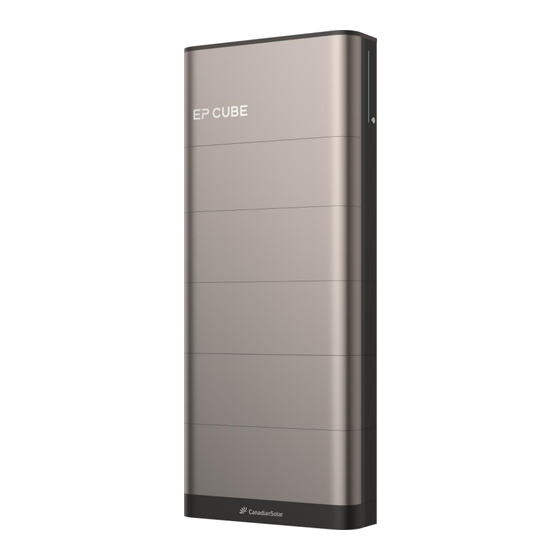
EP Cube HES is an integrated energy storage product that includes both EP Cube PCS and Battery Modules. The number of integrated battery modules can vary between a minimum of 2 modules to a maximum of 6 modules connected in series with EP Cube PCS. (Refer to EU Specification for more details) -
Page 16: Ep Cube Pcs
A. EP Cube PCS Front Cover Wi-Fi Module Status LEDs Power Button AC Outlet Heat Sink Communication Outlet WIFI/BT Outlet PV Outlet Page.16... -
Page 17: Ep Cube Battery Module
B. EP Cube Battery Module Mating Connector Vent Handle Top Cover Mating Connector Screw Hole Locating Pin C. EP Cube Base Mating Connector ScrewHole Base Bracket Top Cover Mating Connector Locating Pin Page.17... -
Page 18: Ep Cube Ac Switch Box
D. EP Cube AC Switch Box(optional) AC Switch Box Page.18... -
Page 19: Operation Modes
2. Operation Modes The EP Cube has 3 different operation modes designed to accommodate a wide range of energy preferences and different needs . 2.1. Self-Consumption Mode During this mode power generated by PV is utilized to supply power to connected loads as a priority. -
Page 20: Time Of Use Mode
2.3. Time of Use Mode This mode offers time-based control for best cost efficiency if the electricity cost varies throughout the day. TOU mode offers mainly 3 features to configure EP Cube to meet diverse power needs under different scenarios. -
Page 21: Warning Labels Description
Temperature surface to avoid being burnt as it can get hot Risk of Electric shock! High voltage exists even High after the EP Cube is Voltage/Delayed powered off. Wait 5 Discharge minutes after power off until the components are completely discharged. -
Page 22: Product Labels
4. Product Labels Figures given below show the product labels of EP Cube PCS, and EP Cube Battery Modules. These product labels provide key parameters for inverter and batteries including nominal voltages, currents, rated power, storage capacity, and operating conditions. This information is visible to qualified professionals during the installation and operation. -
Page 23: Ep Cube Installation
CAUTION Installation considerations for the areas with extreme snow fall: □ It is highly recommended to not install EP Cube HES in places where it is directly exposed to snow or where snow can be accumulated in surrounding spaces. □ Ensure to install a protective roof cover and snow fence. If the installation must be performed outdoor in such conditions. - Page 24 • The minimum space required from the back of the EP Cube to the mounting wall is adjusted by the wall bracket and PCS L bracket. Refer to the details on page 30 for the base installation.
- Page 25 1.2 Required Tools This section lists down the required tools and materials needed during the installation process of EP Cube HES. Tools & Materials Page.25...
- Page 26 Tools & Materials S. No Tool Specs/Quantity Drilling Machine with Drill bit Cutter Marking Pen Tape measure Hammer Electric Screwdriver Cross head Spirit Level Digital Multimeter Socket Set Wire Stripper Wire Cutter Plier Wrench Insulation sleeve As required Cable Ties As required Anchor Bolts As required, Φ5.5*8 Pcs...
-
Page 27: On Site Installation
Ensure that the installation surface is flat by using a spirit level. Ensure there is no gap between the installation surface and EP Cube brackets. Any gaps may lead to accumulated exposure of water. It can cause corrosion and therefore the product could fall . - Page 28 4. Base Bracket M6 Screws- 4pcs 2. Base Back Bracket- 2pcs Note: Put the Side Covers aside until installation is complete. EP Cube Wall Mounting Kit Box (optional 1. Wall Mount Bracket E1- 2pcs 3. Wall Mount-Bracket M6 Screws- 4pcs 2.
- Page 29 98 mm 7.0 N-m Anchor bolts for floor installation Holes for Floor Installation: M8 Note: Bolts for installation on foundation are not provided by EP . CAUTION: Please keep a safe distance between the EP Cube HES and other objects. Page.29...
- Page 30 Wall mounted: Install Wall-mount Kit and Base a. Assemble the Wall-Mount bracket ( referred as E ), attach Bracket E1 to the Bracket E2 from the left and right sides with the M6 bolts. Tighten the bolts by using the screwdriver. b.
- Page 31 d. After drilling the holes, insert anchor bolts in the drilled holes. Remove the washers and nuts. Place the wall-mount bracket on the bolts, place the washers and fasten the nuts manually. Check the level of installed wall mount bracket with sprit level, and use electric screwdriver to tighten nuts to properly install the wall-mount kit on wall.
- Page 32 EP Cube PCS Box 1. EP Cube PCS- 1pcs Davelon PV Connectors(Male)-2pcs 2. EP CUBE HES User Manual- 1pcs Davelon PV Connectors(Female)-2pcs 3. Single Phase Smart Meter- 1pcs 11. Davelon Connector Contact Pins (Male)- 2pcs 4. Smart Meter Communication Cable (10m)- 1pcs Davelon Connector Contact Pins (Female)- 2pcs...
- Page 33 2. CT(with 5m cables)- 1pcs EP Cube Battery Module Box 3. Battery Side Bracket- 2pcs 1. EP Cube Battery Module- 1pcs 2. Battery Module Side Cover- 2pcs 4. Battery Back Bracket- 2pcs Note: Put the Side Covers aside until installation is complete.
- Page 34 Install the Frist Battery Module Carefully place the Frist Battery Module on top of the base and ensure that battery mating connector sockets are well aligned. Matting Connectors b. Fasten the back brackets between the battery module and base using screws, and manually tighten them.
- Page 35 Install the Second Battery Module a. Carefully place the Second Battery Module on top of the first Battery module and ensure that battery mating connector sockets are well aligned. b. Fasten the back backet between adjacent battery modules, on the protruding column at the back of the battery modules using screws (on both the left and right sides), and manually tighten them.
- Page 36 Install the remaining Battery Modules Carefully install remaining Battery Modules one by one by repeating the steps “a and d”. Ensure that battery mating connector sockets are well aligned for each battery module. The pair of protruding columns at the back of each module also have a locating pin on top to help with the alignment of adjacent modules.
- Page 37 Battery Top Bracket 7.0 N-m Installation of the Battery Top Brackets a. The battery module on top of the stack requires the installation of the battery top brackets before its placement on top of the stack. b. Place the Top Brackets on the protruding column at the back of battery module.
- Page 38 Choose the holes and mark them on the wall through the bracket using a pencil. Drill the holes to mount the EP Cube PCS Wall Bracket. For Concrete walls: Use anchor bolts Φ5.5*80mm or use the Φ5.5*80mm hex...
- Page 39 PCS Wall Bracket Wall Bracket Battery Top Bracket Install the EP Cube PCS Wall Bracket a. Carefully place the Wall Bracket on top of the Battery Top Brackets. b. Choose the holes positions and mark them on the wall through the wall mounting bracket by using a pencil.
- Page 40 Fasten the EP Cube PCS Wall Bracket to the Battery Top Bracket PCS Wall Bracket 7.0 N-m Battery Top Bracket e. Finally, fasten the wall bracket with battery top brackets with the bolts latched on the wall bracket, on both right and left sides.
- Page 41 PCS L Bracket. CAUTION: The Side Brackets between the EP Cube PCS and top battery module must be installed first, only after that fasten the EP Cube PCS Bracket & PCS Wall Bracket with the help of PCS L Bracket.
- Page 42 CAUTION: NON-FLAT WALL ALERT!! Do not fix the last two screws (right and left L-brackets to the wall side) until you make that check. The EP Cube PCS is heavy, Please use lifting tools or multiple people to lift it for your own safety. Page.42...
-
Page 43: Installation Of Ac Switch Box
3.Installation of the AC Switch Box(Optional) This section introduces the AC Switch Box installation process in sequence.. Start Installation : Locating the mounting holes Mark the drill positions for the holes on the installation area by using a tape level tool, and pencil. Place the AC switch Box on the wall, choose and mark the appropriate hole positions. -
Page 44: The Ep Cube System
System Topology Without AC Switch Box The EP Cube AC switch box is an optional component. If a homeowner chooses not to install it then it is the installer’s responsibility to ensure that wiring the connections are carried out in a manner that guarantees the same functionality as with the optional EP Cube AC switch box. - Page 45 DC PV Arrays Backup Loads Non-Backup Loads Panel Panel EP CUBE HES Non-Backup Loads EV Charger Backup Loads Wiring the EP CUBE PCS without EP Cube AC Switch Box NOTE: Ensure to follow any applicable local Electrical codes and Standards. Page.45...
-
Page 46: Wiring & Commissioning
OCPD before the integration into the system. So any connected devices, such as an EP Cube, DC, or AC-coupled PV system will need an OCPD before it is connected with the EP Cube. It is recommended that the installer should add circuit breakers before connecting these devices to the system. -
Page 47: Wiring From Solar Panels To Ep Cube Pcs
Cube PCS via a pair of standard industrial Davelon PV connectors. Carefully connect the PV+ and PV- wires to the corresponding terminals of the EP Cube PCS (Refer to the figure on the next page) • Push the Davelon PV connector into the mating connectors on the EP Cube PCS until both connectors are locked into proper place. - Page 48 “click” sound. Figure. Preparing Davelon connectors for PV Strings PV (+) PCS (+) PV (-) PCS (-) Recommended wire gauge: Davelon connector PV cable 4mm²-6mm² Figure. EP Cube PCS to PV Array DC Input Wiring Page.48...
-
Page 49: Ac Wiring From Ep Cube Pcs To Ac Switch Box
Route the other end of the wires through the cable gland dedicated for the AC power, and connect the wires to the terminals labelled as L and N of Grid terminals inside EP Cube PCS. e. Connect the ground wire to the grounding busbar on both ends.(Refer. - Page 50 Preparing Cables with Crimping OTs Insulation for Ground Wire Sleeve a. Take appropriate OT/OD terminals according to the wire gauge size. b. Strip the wire, and conductor length (B) wire should be few 2-3 mm longer than OT/OD length (A). Terminal c.
- Page 51 3. Push down the mechanical flange back to its original position to lock the terminals. Refer to picture above for wiring the AC power L, N, and ground cable between the EP Cube PCS and AC switch box terminals. Page.51...
- Page 52 Step-4 Wiring Connections of Grid a. Prepare the wires for connection between Grid MCB terminals in AC Mains panel and the AC switch box grid terminals. b. Route the wires through cable gland on the bottom of AC switch box, and connect it to terminals labelled as L and N of GRID port.
- Page 53 Step-5 Wiring Connections of Loads a. Prepare the wires for connection between Home Loads MCB terminals in AC Mains panel and the AC switch box Loads terminals. b. Route the wires through cable gland on the bottom of AC switch box, and connect it to terminals labelled as L and N of Loads port.
-
Page 54: Wiring Of Other Components
Please ensure that the main breaker of the Grid is turned off and protected with Lockout/Tagout. A. Wiring of Emergency Stop a. Remove the press-fit jumper or jumper wire on the EP Cube PCBA connector between the EPO+ & EPO- terminals. Recommended Wire Gauge: 2-core signal cable/ 0.50mm²-0.34mm²... - Page 55 (L phase) shall be from Grid to MCB (Grid → MCB). • The CTs provided with the EP Cube has a standard cable length of 5m. • The recommended cable size & gauge values are 2-core signal cable/20-22AWG.
- Page 56 Meter AC Power Wiring Figure. b RS 485 Signal Wiring Between Meter and PCS RS485 Wire Gauge: 2-core shielded twisted pair cable/0.50mm²-0.34mm² Figure. c Page.56...
-
Page 57: Ep Cube Commissioning
• Please ensure PPE is properly worn before getting started. • EP Cube commissioning requires EP Cube PCS to have AC Power. It must be ensured that Grid MCB is at on state. But Do not press the power on/off button on the right side of the EP Cube PCS a. - Page 58 c. Turn on the MCBs (ON GRID Breaker & AC Boost Breaker) inside the AC Switch Box. Ensure that the Bypass MCB is turned off, and locked out & Tagged out. AC switch box AC switch box d. Turn on the PV Switch by turning knob from OFF to ON. Both PV1 & PV2 are controlled through a single switch.
-
Page 59: Commissioning Via Ep Cube App
2.2. Commissioning via EP Cube app System commissioning and setup have been made easy by the EP Cube app. It enables the user with system commissioning, monitoring and basic troubleshooting by providing errors and fault lists with the installer account. - Page 60 Follow the step by step process to configure all the connected devices within your EP Cube system including Network i.e. Bluetooth/Wi-Fi, Grid, HES config, and warranty registration. Below fig shows the order of configuration steps. At each step, there are 3 navigation buttons to enter “Config”, and move to “Next”...
- Page 61 C h o o s e c o u n t r y n a m e f r o m C o u n t r y t h e l i s t D e v i c e C h o o s e s t a t e n a m e f r o m t h e S t a t e L o c a t i o n...
- Page 62 3- Wi-Fi Config: it allows you to choose your home Wi-Fi network to connect your device with it. Input the password and click confirm. Note: EP Cube can only connect with 2.4Ghz Wi-Fi Networks. Input the password and confirm Turn on Wi-Fi...
- Page 63 Update Progress Click update Button Once the update is completed successfully, Enter EP Cube button will appear. Clicking on the button will start the second part of the update that’s EP Cube system firmware update. EP Cube Update page...
- Page 64 Click update button on EP Cube page to start the update. Once the update is completed successfully, click the finish button. EP Cube Update Update Progress completed Finish to return to Installation For any reason if update process failed, the Upgrade failed message will be displayed.
- Page 65 Note: maximum 6x battery modules are integrated with an HES (EP Cube PCS). Step 4. Finally, input open circuit voltage (Voc) for the connected PV strings. Note: maximum 2x PV array can be connected with an HES(EP Cube PCS) module. Step 5. Click Submit & return to installation steps.
- Page 66 HES Config-E STOP HES Config-Batteries HES Config-PV strings Page.66...
- Page 67 7- Warranty Registration: In the final step, take photos of the completed installation from different aspects and upload using add button. Maximum 20 pics can be added. Note: If you had trouble with scanning any QR codes at add device step, then manually input the device SNs, take photos of the QR code and upload the photos of the problematic QR code here.
- Page 68 After completing the finish step, return to home page. Select an appropriate operation mode and Reserve SOC value according to energy usage preferences. Now, install the side covers and switch on the EP Cube PCS via the power button as shown in the figure below...
- Page 69 Observe and verify that EP Cube is working as per desired settings. Pay attention to EP Cube indication LED and energy flow on the EP Cube App. Status LED Indication Description Stand by Mode Bright & Solid Stand by Run Mode Faint &...
-
Page 70: Ep Cube Energize And De-Energize
3. EP Cube System Energize and De-energize This section introduces the EP Cube system’s energize and de-energize process. 3.1. EP Cube Energize CAUTION: • Please ensure all the cables are connected well before getting started. a. Turn on the Grid MCB inside the Main Home Electrical panel. - Page 71 Turn on the PV Switch by turning knob from OFF to ON. Both PV1 & PV2 are controlled through a single switch. d. Switch on the EP Cube PCS via the power button as shown in the figure below Page.71...
-
Page 72: Ep Cube De-Energize
3.2. EP Cube De-energize a. Switch off the EP Cube PCS via the power button as shown in the figure below b. Turn off the PV Switch by turning knob from ON to OFF. Both PV1 & PV2 are controlled through a single switch. - Page 73 c. Turn off the MCBs (ON GRID Breaker & AC Boost Breaker) inside the AC Switch Box. Ensure that the Bypass MCB is turned off, and locked out & Tagged out. AC switch box AC switch box d. Turn off the Grid MCB inside the Main Home Electrical panel. Main panel Page.73...
-
Page 74: Troubleshooting & Maintenance
. In that case you can check on the Indication LEDs on the right side of EP Cube PCS to see if LEDs are flashing or lit solid. If the system is in restart process, then LEDs will be flashing. -
Page 75: Appendix
APPENDIX Technical Specs: Please refer to Technical datasheet for more specific parameters. Page.75...
Need help?
Do you have a question about the EP CUBE and is the answer not in the manual?
Questions and answers