Table of Contents
Advertisement
Quick Links
Advertisement
Table of Contents

Related Manuals for Elektor TAPIR

Summary of Contents for Elektor TAPIR
- Page 1 Elektor “TAPIR” E-Smog Detector Kit Construction Manual SKU 20579...
- Page 2 Publishers’ Notice: The latest version of the Construction Manual of the “TAPIR” E-Smog Detector Kit supplied by Elektor is available as a pdf file at: www.elektor.com/..Elektor “TAPIR” E-Smog Tester Kit | Construction Manual...
-
Page 3: Table Of Contents
Page This document is complementary to the information contained in: 1 – Kit Contents 1. the article “TAPIR Sniffs it Out!” published in Elektor Magazine edition 7&8 2012; 2 – Required Items 2. the engineering background, reader queries, and related discussions posted on the Elektor Labs website. -
Page 4: Kit Contents
3 capacitors, 10 µF (C2, C3, C4) › Figure 1. Kit contents, as received. 1 diode, BAT54S (D1) › 1 switch › 1 3.5-mm audio jack › 1 spring for battery › Elektor “TAPIR” E-Smog Tester Kit | Construction Manual 4/15... -
Page 5: Required Items
› electrical shock, always ensure that the antenna is properly insulated. Figure 2. Some of the items and tools required to assemble the TAPIR kit. The following items are required for the proper assembly of this kit: A well lit and tidy work surface ›... -
Page 6: The Panel
Figure 6. Top view of PCB breakout Panel 120354 v2.2 for the TAPIR E-Smog Detector. heating the joint. In general, short soldering times produce clean and tidy joints. -
Page 7: Assembly
PCBs from the PCB panel and file off the tabs. Figure 7. Bottom view of PCB breakout Panel 120354-1 v2.2 for the TAPIR E-Smog Detector. Figure 8. Slide switch S1 and headphones connector K2 soldered. Elektor “TAPIR” E-Smog Tester Kit | Construction Manual 7/15... - Page 8 6. T1 (MMBT3904; marking: 1AM) 7. T2 & T3 (BC847, marking: 1F or 1FW) Figure 12. Detail of the temporary battery connection. Figure 10. Detail of PCB 3 with C1, C3, R1–R5, T1–T3 fitted. Elektor “TAPIR” E-Smog Tester Kit | Construction Manual 8/15...
- Page 9 If the tip of your soldering iron is too thick for proper access to these joints, consider using a piece of solid wire to Figure 14. PCB 3 removed from the panel. Elektor “TAPIR” E-Smog Tester Kit | Construction Manual 9/15...
- Page 10 PCBs 2, 3 and 6, and between Figure 20. The two standoffs soldered securely. PCBs 2, 3 and 6. Place the TAPIR on the bench with PCB 2 facing down and solder the joints between PCBs 5, 6 and 7 and PCB 2. Check that all...
-
Page 11: The Antennas
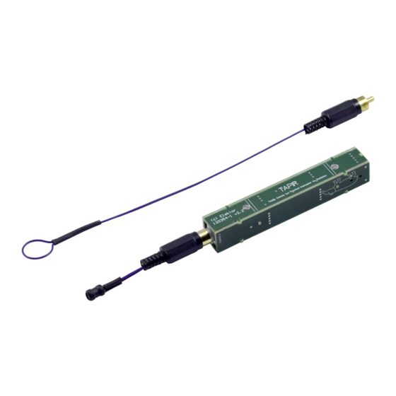
“sniffing out” electrical noise on, say, a circuit board, but carefully! Figure 23. Finished assembly of the Elektor TAPIR. Figure 26. Loop at one end of the wire. At the other end of the wire, strip off approximately 3 mm of the insulation and slide the Cinch connector shell over the wire. - Page 12 5 cm long and strip their ends. Figure 31. Finished H-field antenna. Bear in mind that when you hold the TAPIR in your hand, your body is part of the antenna, which may increase the audible hum level.
-
Page 13: Bill Of Materials
1 mm wire, 50 cm, black 10 cm heat shrink tubing, black, diam. 4 mm, 4:1 shrink ratio Headphones, cabled, with standard 3.5-mm plug PCB (panel with 7 PCBs), Elektor 120354-1 v2.2 Elektor “TAPIR” E-Smog Tester Kit | Construction Manual 13/15... -
Page 14: Schematic And Pcb Layout
9 – Schematic and PCB Layout Figure 33. Top overlay of PCB Panel 120354-1 v2.2 Figure 32. Schematic of the Elektor “TAPIR” E-Smog Detector (120354-1 v2.2) Figure 34. Bottom overlay of PCB Panel 120354-1 v2.2 Elektor “TAPIR” E-Smog Tester Kit | Construction Manual... - Page 15 Figure 35. Copper on top of PCB Panel 120354-1 v2.2. Figure 36. Copper on bottom of PCB Panel 120354-1 v2.2. Elektor “TAPIR” E-Smog Tester Kit | Construction Manual 15/15...
Need help?
Do you have a question about the TAPIR and is the answer not in the manual?
Questions and answers