
Summary of Contents for Sole Digital TFL300
- Page 1 Wireless Process Indicator Model: TFL300 Installation and User Manual Revision 01 – October 2023 © CASWA Pty Ltd – 2018...
-
Page 2: Table Of Contents
Installing the FSU application ................... 6 4.1.3 Launching the application ..................6 4.2 Connecting to the Device ......................7 4.3 Managing Firmware ........................ 8 4.4 TFL300 Configuration ......................10 4.4.1 Standard TFL300 Configuration ................10 APPENDIX A: FSU SYSTEM REQUIREMENTS ................. 10 2 | Page ©... -
Page 3: Overview
1 OVERVIEW Take the pain out of installing traffic lights with TFL300 with just two wires and two screws you can add an inexpensive electronic load indicator that’s quick, easy and safe to set up. Product Description TFL300 works by connecting wirelessly to any HoistNet device and changing and using bright coloured LEDs to indicate the load, pressure, windspeed that the remote device is measuring. -
Page 4: Specifications
2.2 Electrical Specifications Parameter Description Units Supply voltage Current consumption Note1 Allowable operating temperature °C Note1: Extended operation at maximum temperature may reduce the life of the device. 4 | Page © CASWA Pty Ltd – 2014 TFL300 User Manual... -
Page 5: Installation Details
Loosen the two 4mm bolts in the pivot of the bracket to adjust the angle of the display. Loosen the two 5mm bolts in the rear mounting plate to adjust the rotation of the display 5 | Page © CASWA Pty Ltd – 2014 TFL300 User Manual... -
Page 6: Wiring Diagrams
3.1 Wiring Diagrams Figure 2: Connecting to Liftlog or Maxout 4 COMMISSIONING DETAILS Like all SoleDigital products, the TFL300 is configured by the Field Service Utility. 4.1 Installing and Launching the FSU Application 4.1.1 FSU Program Installation Ensure that your computer is switched on, and connected to the internet and that the minimum required software versions are installed. -
Page 7: Connecting To The Device
The Bluetooth link between the Laptop using a Link-2 and a TFL300 has a range of approximately 100m. If you require live support for any of Sole Digital products, either go to our website or open a remote support session, by pressing the icon. -
Page 8: Managing Firmware
Are experiencing a problem and need to roll back to an earlier firmware version that didn't cause the problem you are experiencing; or d) Have been specifically instructed to do so by your TFL300 supplier. To check for new firmware versions or to access old firmware versions, return to the Device Display screen and right-click the desired equipment icon. - Page 9 <Apply firmware> button that appears in the lower right corner of the window: As the message states, DO NOT switch off the TFL300 or the computer running the FSU software or remove the Link2 modem until you are told to do so.
-
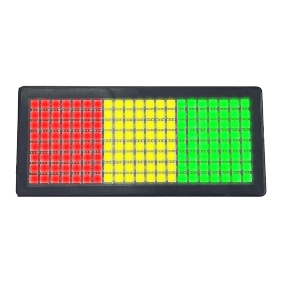
Page 10: Tfl300 Configuration
4.4 TFL300 Configuration 4.4.1 Standard TFL300 Configuration To demonstrate a very typical calibration of a TrafficLite unit let's go back to our example graph from Part 1, a 10-tonne crane with Green until 60%, Orange until 90% and Red until 100%.
Need help?
Do you have a question about the TFL300 and is the answer not in the manual?
Questions and answers