
Summary of Contents for JRP NB127A
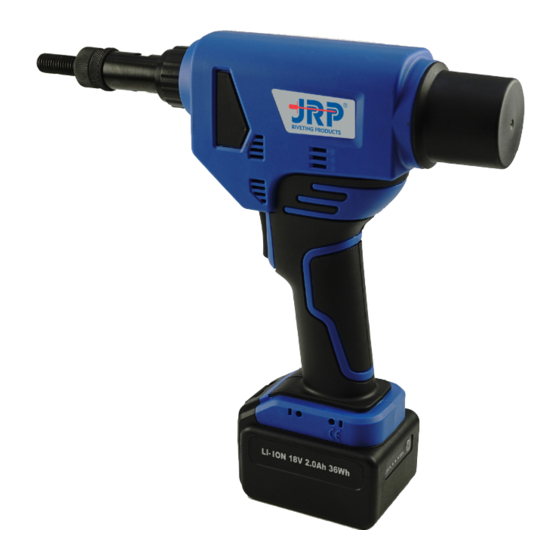
- Page 1 QUALITY • SERVICE • PERFORMANCE NB127A Battery Blind Rivet Nut Tool Installation Manual www.jrprivets.co.uk...
-
Page 2: Table Of Contents
Contents Page SAFETY INSTRUCTIONS/WARNINGS TOOL MAINTENANCE AND ENVIRONMENTAL COMPLIANCE TOOL OVERVIEW Key Parts Technical Dimensions and Capacity Wearing Parts and Accessories Wearing Parts List Full Parts List and Exploded Drawing PREPARATION BEFORE USE Changing the Mandrels Setting the Mandrel/Head and Adjustment Nut Checking the Battery Checking the Tool FUNCTION SETTINGS... -
Page 3: Safety Instructions/Warnings
SAFETY INSTRUCTIONS/WARNINGS To reduce the risk of personal injury to yourself and/or others, or property damage, please be sure to follow the safety instructions below. Description of the warnings: - A cause of potential danger of serious injury/death. Danger Warning - A cause of potential danger of serious injury/death. -
Page 4: Tool Maintenance And Environmental Compliance
is recommended to carry out maintenance in advance. • Maintenance of the riveting tool is limited only to replacement of worn par quick wear parts, jaws, jaw sliders, etc., if necessary (see P8 for replaceme sories). TOOL MAINTENANCE AND ENVIRONMENTAL COMPLIANCE •... -
Page 5: Technical Dimensions And Capacity
2 | Deutsch 5 | English ameters Technical Dimensions and Capacity 1.1 Capacity / Technical parameters 21.5 21.5 21.5 21.5 93,5 GO-RN1 GO-SN1 GO-SN1 Technical Data Model GO-RN1 GO-RN2 GO-SN1 GO-RN1 GO-RN2 GO-SN1 Capacity M3-M12 Motor 18V Brushless motor Material Capabilities All round body, semi and full hexagonal blind 18V Brushless motor rivet nuts in all materials. -
Page 6: Wearing Parts And Accessories
Wearing Parts and Accessories · FigA · Standard se Configuration/Accessories Interchangable parts——NB80WA-NB120A-NB100LA Wearing Parts List Name Spec Qty. No. Name Spec Qty. Code Code Battery Z41718H00 Wrench L41244H00 18V-2.0A-36Wh Article Number Description Qty/Tool Charger Z41719H00 18V-2.0A Plastic box B01642H00 TSBL43249H00 M6 Head Hex-key F60273H00... -
Page 7: Full Parts List And Exploded Drawing
Full Parts List and Exploded Drawing Turnover for full list... - Page 8 Full Parts List Article Number Spec. Qty/Tool Description TSBL43249H00 M6 Head TSBL43232H00 Adjustment Nut TSBL43243H00 M6 Mandrel TSBL23002H00 Screw Cover TSBZ42050H00 Nosepiece Pedestal TSBZ42078H00 Cover Tube TSBZ42051H00 Gear Box TSBZ42074H00 Brushless Motor TSBZ41806H00 Gears Assembly TSBF60577H00 Self-Drill Screw TSBZ41709H00 Body (Blue) TSBL42296H00 Rear Cover TSBZ42076H00...
-
Page 9: Preparation Before Use
2 | Deutsch 9 | English 2. Preparation of the tool PREPARATION BEFORE USE 2 | Deutsch 9 | English Before operating the riveting tool, please read the following important instructions carefully. - Please read the instructions carefully before use. Danger Danger - 2.1 Exchange of the mandrels Changing the Mandrels... -
Page 10: Setting The Mandrel/Head And Adjustment Nut
English | 10 Deutsch | 2 Setting the Mandrel/Head and Adjustment Nut The setting of the mandrel/head and adjustment nut correctly is all according to the length of the blind rivet nut to be 2.2 Adjustment of the mandrel used. Adjust the length of the mandrel correctly according to the length of the blind rivet nut The setting up is as follows: (see fig.) The order of adjustment is as follows:... -
Page 11: Checking The Battery
According to the above illustration: ① Sscrew the blind rivet nut onto the mandrel ② loosen the counter nut, adjust according to ③ and ④ as the figure ⑤ shows, check that the mandrel protrudes ≈ 1.5 mm above the blind rivet nut after adjustment - the mandrel is correctly adjusted ⑥... -
Page 12: Function Settings
3.1 Adjusting the traction force The function is preset at the factory: Stroke: 0.3 - 0.8 mm (indicator light 1) FUNCTION SETTINGS Traction mode: (L) "green light on, not flashing". Read the following important notes carefully when you are ready to prepare the function settings Warning The tractive force mode (L) stands for general tractive force. -
Page 13: Setting The Stroke Adjustment
mm to 0.6 mm, the green light is permanently on. The stroke setting is between 1-6 English | 12 Deutsch | 2 mm, 0.2 mm per increased gear (see diagram 2), the total stroke of 6 mm according to diagram (3) is the maximum stroke setting (all 10 lights are on). Press the button again g the stroke briefly, after the full display (all lights), and the stroke goes back to 0.2 mm (see figure setting (indicator lights) can be set/adjusted between 1-10. -
Page 14: Riveting In Conventional Mode
Setting the Stroke Adjustment (cont) Stroke Indicator Stroke Number Setting (mm) Riveting in Conventional Mode (with Fixed Green Light) The tool is factory set for conventional riveting mode. It is recommended to use the conventional riveting mode with all rivet nuts, but especially round body type. In this setting when the rivet nut is threaded onto the mandrel with slight pressure the tool automatically screws on until the rivet nut meets the head. -
Page 15: Tool Operation
(before official riveting) (Fig. 1) We before any continual use. The use of JRP brand rivet nuts is recommended for optimum performance. recommend that you use GOEBEL brand blind rivet nuts for optimum processing. -
Page 16: Manually Unscrewing Rivet Nuts
4.2 Checking the set blind rivet nut 4.2 Checking the set blind rivet nut king the set blind rivet nut If after the setting process the result of the blind rivet nut setting appearance does not If after the setting process the result of the blind rivet nut setting appearance does not e setting process the result of the blind rivet nut setting appearance does not correspond to the picture in the middle, it shows that the stroke has not been set to the correspond to the picture in the middle, it shows that the stroke has not been set to the... -
Page 17: Charger And Batteries
CHARGER AND BATTERIES Charger Technical Capabilities Output 18V-2.0A Input 100-240V – 50-60HZ/1A Net Weight 0.27Kg Gross Weight 0.31Kg When the charger is connected to the power supply and working normally, the indicator light ① is always green. The battery is loaded in the direction of the arrow. ②... -
Page 18: Faq (Questions/Answers)
FREQUENTLY ASKED QUESTIONS Q: Is the battery okay if it is not used for a long time? A: As with all batteries they will deteriorate without use, so please re-charge every six months. Q: Does charging after each use affect the battery life? A: To extend the lifespan of the battery it is recommended to use up to full charge, or to at least below 25% (one red light), before fully re-charging. -
Page 19: Troubleshooting Malfunctions
TROUBLESHOOTING Malfunctions Probable Causes Corrective Action Battery loaded into charger, the Stop charging immediately, Battery malfunction or damage, green light is on, but it is not fully remove the battery, and error, unable to charge. charged. replace it with a new one. When The charger has either stopped Cut off the power immediately,... -
Page 20: Ce/Ukca Certification And Warranty
WARRANTY The 12-month return to base warranty for this tool is from the date of purchase. Proof of purchase will be required for any warranty claims. All wearing parts are not covered by the warranty. Damage caused by normal wear and tear, overloading, improper use or by unqualified personnel is not covered by the warranty.
Need help?
Do you have a question about the NB127A and is the answer not in the manual?
Questions and answers