Table of Contents
Advertisement
Quick Links
Advertisement
Table of Contents

Summary of Contents for ANEP PGU
- Page 1 PGU GSM GATEWAY LIFT EQUIPEMENT NT_ANEP_PGU_EN_06_09_2023...
-
Page 2: Table Of Contents
SUMMARY SUMMARY ..................GENERAL WARNINGS ..............General remarks ................DESCRIPTION ..................Main features ................LEDS ....................INSTALLATION ................... Installation tips ................Consumption table ............... Mounting ..................Inserting the SIM card ..............Antenna installation ..............Remote alarm ................Power supply connection ............. Battery .................. - Page 3 2G signal level measurement ............ SIM / USIM AUTHENTICATION ............. Set / Delete / Read notification no..........Definition / Reading of ANEP protocol tel. no........ Enter / Read ANEP protocol identifier ........... Activation / deactivation of battery charge level control ....
- Page 4 SUMMARY Restart (reboot) ................Reset Factory Settings ........................COUNTRY CODES / OPERATORS GAIN CONTROL ................. AUTOMATIC PHONE NUMBER CONVERTER ......... MEASURE SIGNAL LEVEL ............... BATTERY ALERT ................CONTROL OF EXTERNAL POWER FAILURE ....................SIM CARD PROTECTION READING ADVANCED GATEWAY SETTINGS ........READING BATTERY STATUS ............
-
Page 5: General Warnings
Pay close attention to the warnings in this section, as they provide important guidelines to ensure safe safe installation, correct use and maintenance of the product. • The device must be used EXCLUSIVELY for its intended purpose, and ANEP cannot be held responsible for any damage resulting from improper use. •... -
Page 6: Description
DESCRIPTION PGU is a device which, when connected directly to a landline telephone or remote alarm system, enables calls to be made and received via the mobile network. A SIM card is required for operation. PGU is equipped with an internal back-up battery (to be connected) -
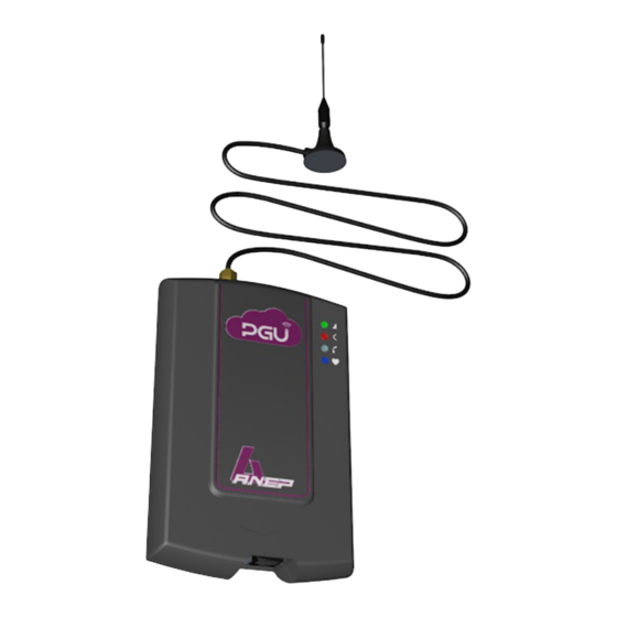
Page 7: Main Features
• Dimensions : 140 x 96 x 28 mm • Weight: 220g LEDS The PGU has 4 externally visible LEDs. For the meaning of the flashing LEDs, please refer to the "Signals" section (see pages 42 to 45). Green LED: 2G mobile network intensity... - Page 8 -------> Remove the cover by pressing on the top side. Green LED GSM network intensity Red LED device status White LED line status Blue LED power supply status ANTENNA cable SMA connector SIM card slot (standard SIM 2FF format) 2G network reception level LED (green) Device status LED (red) Line status LED (white) Power status LED (blue)
-
Page 9: Installation
INSTALLATION Installation tips • The PGU gateway must be installed in a place where the radio signal is sufficient for its correct use (Machinery or other or top of shaft). If the 2m antenna is not available, ANEP can supply an optional ANEP can optionally supply a 10m antenna (ref. -
Page 10: Mounting
• Make two ø5 mm holes in the wall, spaced 50 mm apart. • Insert the 2 wall plugs and screw in the screw up to 5 mm from the wall. • Insert the PGU device through the two rear eyelets onto the 2 screws on the wall. -
Page 11: Inserting The Sim Card
INSTALLATION SIM CARD (STANDARD 2FF FORMAT) Before inserting the SIM card, make sure you are electrostatically discharged and that the device is switched off to avoid damaging it. Take every precaution to avoid electrostatic discharge. WARNING The SIM card must have the PIN CODE DEACTIVATED. If the SIM card has the PIN CODE activated, it must be deactivated using a cell phone. -
Page 12: Antenna Installation
Screw the supplied antenna cable (2m) into the SMA connector (A in photo on page 8), fully extending the cable. To ensure correct operation of the PGU, position the magnetic base antenna so that there are no metal structures to mask the signal. WARNING... -
Page 13: Remote Alarm
INSTALLATION (more) REMOTE ALARM Connect the PGU to a landline telephone or remote alarm system via the RJ11 connector ANEP BOX (D see photo on page 8). connection diagram Connect the PGU to a landline telephone or remote alarm system via the TEL terminal (F, see photo on page 8). -
Page 14: Power Supply Connection
INSTALLATION (more) TRANSFO POWER SUPPLY 230Vac / 12Vdc Power supply via external adapter 230Vac / 12Vdc on terminal E • Connect the external adapter to the appropriate E input (see photo on page 8) Power Note : It is advisable to install 2-wire supply appropriate electrical... -
Page 15: Battery
If the red device status LED flashes faster and stays lit longer (see page 44), the device is not correctly connected to the 2G network, • Unplug the PGU and check that the SIM card is correctly inserted or not blocked by the PIN code. -
Page 16: Programming By Telephone
PROGRAMMING BY TELEPHONE Programming can be carried out manually using a multi-frequency telephone equipped with a keypad.. It is possible to program : = (unhook) • Setting up the roaming service • SMS warning number • Administrator number • The programming password •... -
Page 17: How To Use
BY PHONE PROGRAMMING Function format Description / Information Note: in the "Programming by telephone" table, the factory-set value is shown in bold type. X : option from 1 to 4 1 = by default 2: recommended mode for remote alarms or other devices controlling line tones HOW TO USE 3: recommended mode for remote alarms or other... -
Page 18: Call Codec Setting
BY PHONE PROGRAMMING Function format Description / Information X : option, from 0 to 3 0: EFR (enhanced full rate) and HR (half CALL CODEC rate) activated with EFR preference SETTING (VOICE) 1: EFR and HR activated with HR preference 2: EFR on, HR off 3: FR on, HR off Telephone number with country code (if... -
Page 19: Network Signal Level Measurement
X...X# X...X ANEP PROTOCOL X...X : identification number of the BOX (8 IDENTIFIER digits), or other ANEP product X...X# X : Choice from 0 to 7 0 = 7 hours 1 = 6 h 30 2 = 6 h 00... -
Page 20: Telephone Line Voltage
BY PHONE PROGRAMMING Function format Descriptions / Informations X : choice of 0 to 1 TELEPHONE LINE 0 = 36 Vdc VOLTAGE 1 = 52 Vdc PERIODIC TEST X...X : telephone number to which to X...X X..X# CALL NUMBER send the periodic test X: periodic test mode PERIODIC TEST 0= CLI call... -
Page 21: Battery Status Readout
BY PHONE PROGRAMMING Function format Description / Information PIN CODE X...X X..X# CREATION Pin code limited to 8 digits PIN CODE X: activate / deactivate pin code ACTIVATION / 0= Off DEACTIVATION 1= On PIN CODE MODIFICATION X...X X..X# Pin code limited to 8 digits Tones : 0 tonalité... -
Page 22: Sms Programming
SMS is only authorized via this telephone number. A notification SMS confirming programming is sent from the PGU to the number that sent the programming SMS. WARNING SMS programming carried out and sent via the Internet may not work if the required format is not respected. -
Page 23: Mode / Playback Operating Mode
Reading the operating instructions Answer (example) AN-GWU*0#2R AN?GWU 0#21# => PGU is in mode 1 X from 0 to 1 AN-GWU*0#5x# X: 0 on X: 1 off BATTERY CHECK Reading of battery charge level control (from... -
Page 24: Playback / Transmitter Gain Adjustment
(VOICE) Call codec playback Answer (example) AN-GWU*0#15R AN?GWU 0#15 => 2 = EFR and HR activated / ANEP AN-GWU* X..X : telephone number with country code (if 0#18*X..X defined, this is the only number from which SMS programming is permitted) *X..X#... -
Page 25: Dialed Phone Number Converter
PROGRAMMING Function format Description / Information CALL NUMBER ENTRY COUPLING AN-GWU*0#25* X...X : programming password X..X*Y* Y : table position, from 1 to 6 Z..Z*Z..Z# Z...Z : phone number CALL NUMBER DELETION COUPLING AN-GWU 0#25* X...X : programming password X..X AUTOMATIC Y : table position, from 1 to 6 DIAL NUMBER... -
Page 26: Sim / Usim Authentication
PROTOCOL ANEP Reads the telephone number designated to AN-GWU*0#42R receive the ANEP protocol AN-GWU* X...X : identification number of the BOX 0#44* (8 digits), or other ANEP product X..X*X..X# ANEP PROTOCOL IDENTIFIER Reading ANEP product identification number AN-GWU*0#44R (8 digits) -
Page 27: Battery Threshold
PROGRAMMING Function format Description / Information X : Choice from 0 to 7 0 = 7 hours 1 = 6 h 30 2 = 6 h 00 3 = 5 h 30 4 = 4 hours (by default) AN-GWU*0#52*x# 5 = 2 h 30 BATTERY 6 = 1 h 30 THRESHOLD... -
Page 28: Periodic Test Call Number
PROGRAMMING Function format Description / Information AN-GWU*0#72* X...X : telephone number to which to send the periodic test PERIODIC TEST X…X*X…X# CALL NUMBER AN-GWU*0#72R Reading the periodic test call number X: periodic test mode AN-GWU*0#73* 0= CLI call X...X*X...X# PERIODIC TEST 1= SMS MODE AN-GWU*0#73R... -
Page 29: Gateway Type Identification
PROGRAMMING Function format Description / Information X...X: pin code AN-GWU*0#82* The pin code must be identical to the sim code PIN CODE X...X*X...X# and limited to 8 digits... CREATION AN-GWU*0#82R Lecture du code PIN création 0: Off AN-GWU*0#83*X# PIN CODE 1: On ACTIVATION / DEACTIVATION... - Page 30 PROGRAMMING Function format Description / Information Answer (example) AN-GWU*0#RCRFRG AN?GWU objcobytel.com#F#G# x : Operator APN (APN = Operator's Network Access Point) y : APN user (in option) APN SELECTED z : APN password (optional) ORANGE -> AN-GWU 0#Corange#Forange#Gorange# BOUYGUES -> AN-GWU 0#Cmmsbouygtel.com#F#G# AN-GWU* BOUYGUES ->...
-
Page 31: Country Codes / Operators
(1) COUNTRY CODES / OPERATORS MCC : cell phone country code 208: France 212: Monaco MNC : mobile network code 01: Orange 10: SFR 20: Bouygues 10: Monaco Telecom (2) GAIN SETTINGS CODE CODE See programming tables by PHONE These settings allow you to adjust the gain of the transmitter and receiver. WARNING The default values stored are the optimum ones, modify them only if really necessary. -
Page 32: Automatic Phone Number Converter
(3) AUTOMATIC CONVERSION OF DIALED PHONE NUMBERS (ROUTING AND PAIRING) CODE CODE See programming tables by PHONE If the function is activated, instead of dialing the telephone number from the connected telephone (BOX-TA remote alarm or other telephone device), the gateway forwards the call to a predefined number. - Page 33 When you select a number not listed in the "Selected phone number" column, the gateway sends a call to the first phone number listed in the "Predefined phone number" column. Automatic phone number matching • Enter the number to be called in a location on the table using programming code 26..
-
Page 34: Measure Signal Level
(4) MEASURE SIGNAL LEVEL CODE See programming tables by PHONE This procedure lets you check the 2G (GSM) signal level via your phone, or by SMS. By phone : • Lift the handset and dial ⁕⁕30#. • Wait for the signal to be read.. The gateway will send a number of short tones corresponding to the signal level: Tones Quality... -
Page 35: Battery Alert
CODE CODE See programming tables by PHONE If the low battery check is enabled, the PGU checks the battery charge level at all times. When the charge level falls below the level required to guarantee 4 hours of standby time, a warning message is sent to a pre-registered number. -
Page 36: Control Of External Power Failure
(6) EXTERNAL POWER FAILURE CHECK CODE See programming tables by PHONE If external power failure monitoring is enabled, the gateway continuously checks the external power supply (230Vac or 12Vdc). If the external power failure lasts longer than the predefined time interval, an SMS notification is sent with the following text message: "External power supply failure If external power is restored for an interval equal to the preset threshold, a new... -
Page 37: Sim Card Protection
<pin code> <pin code># if you wish to change the pin code Example: SIM with PIN code 0000 You need 0000 0000# then Versions from which PIN code protection is possible PGU module Telit 4.10.06 PGU module Cinterion 2.09.12 NT_ANEP_PGU_EN_06_09_2023... -
Page 38: Reading Advanced Gateway Settings
: AN-GWU Start of program chain xxx# password string (by default xxx = 0) ⁕ PGU will send one or two SMS messages to the number that sent the request, with the following information: Values Meaning (values shown are for illustrative... -
Page 39: Reading Battery Status
(9) READING BATTERY STATUS CODE See programming tables by PHONE If battery charge level monitoring is enabled, the PGU device can be interrogated for battery status.. This procedure allows you to check the battery status via your phone, or by text message.. -
Page 40: Rebotting
(10) RESTART (REBOOT) CODE See programming tables by PHONE The PGU can be restarted at any time by telephone or SMS, without having to disconnect the power supply. Note: : Restarting the PGU does not modify its programming. (11) RESET FACTORY SETTINGS... -
Page 41: Services
SERVICES Incoming calls Answers incoming calls. When a telephone call is received, the line status LED (white) flashes briefly 4 times every 4 seconds, as described in the "Signals" section (see page 44), and the telephone rings.. • Lift the handset to answer the call. The line status LED (white) and the device status LED (red) light up, and communication with the caller is established.. -
Page 42: Signals
SIGNALS TONALITY Invitation to dial (continuous tone) : 0" 1" 2" 3" 4" 5" Indicates that the device is ready to receive the selection. Deterrence : 0" 1" 2" 3" 4" 5" Indicates that there is a delay in programming selection, that the caller has hung up or that unauthorized access has been made.. -
Page 43: Call Signalling
Signal quality : 0" 1" 2" 3" 4" 5" Indicates high signal level. Signal quality : 0" 1" 2" 3" 4" 5" Indicates absence of signal. CALL SIGNALLING 0" 1" 2" 3" 4" 5" Indicates the arrival of an incoming call. LED (GREEN) 2G network intensity 0"... -
Page 44: Red - Device Status
Operation of the green LED when the gateway is powered up 0" 1" 2" 3" 4" 5" indicates that the SIM card is PIN-protected. 0" 1" 2" 3" 4" 5" indicates that the SIM card is protected by the PUK code. Device status LED (RED) 0"... - Page 45 0" 1" 2" 3" 4" 5" 6" 7" 8" 9" 10" Indicates that the power supply is connected and the battery charge is high. 0" 1" 2" 3" 4" 5" 6" 7" 8" 9" 10" Indicates that the power supply is connected and the battery charge is average. 6"...
-
Page 46: Problem Solving
Check mobile network coverage coverage with a cell phone Insufficient power supply Check power supply Problème générique de Switching the PGU on and logiciel Move the PGU and The red LED flashes (as Mobile network signal level antenna to a position... -
Page 47: Warranty
ANEP cannot be held responsible for any loss of data, as well as any special or incidental damage, resulting from incorrect implementation or improper use of the product. - Page 48 TH E AF T ER SALES SER VI CE I S P R OV I DE D B Y 4 bis rue de Paris 94470 Boissy-Saint-Léger +33 1 45 98 34 44 Website : www.anepstore.com NT_ANEP_PGU_EN_06_09_2023...
Need help?
Do you have a question about the PGU and is the answer not in the manual?
Questions and answers