
Related Manuals for GEA FLOWVENT

Summary of Contents for GEA FLOWVENT
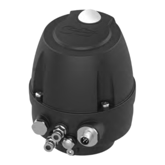
- Page 1 Control and feedback systems GEA FLOWVENT Control Top Operating instruction (Translation from the original language) 430BAL014912EN_3...
- Page 2 EU Machinery Directive. This document is protected by copyright. All rights reserved. The document may not be copied, reproduced, translated or converted to an electronic medium of machine-readable form, in whole or in part, without the express permission of GEA Flow Components India. LEGAL NOTICE Word marks ®...
-
Page 3: Table Of Contents
TABLE OF CONTENTS General Information Information on the Document 1.1.1 Binding Character of These Operating Instructions 1.1.2 Notes on the Illustrations 1.1.3 Symbols and Highlighting Herstelleranschrift Contact Safety Intended use 2.1.1 Requirements for operation 2.1.2 Improper operating conditions Operator’s Duty of Care Subsequent changes IP Protection classes General safety instructions and dangers... - Page 4 Mounting hood Alarms 11.1 Malfunctions and remedies Decommissioning 12.1 Safety precautions 12.2 Disposal 12.2.1 General notes Spare Parts List - Control Top FLOWVENT Control Top (FLOWVENT-CT) Dimension sheet - FLOWVENT Control Top Appendix 15.1 Lists 15.1.1 Abbreviations and terms 430BAL014912EN_3 25.01.2024...
-
Page 5: General Information
General Information Information on the Document General Information Information on the Document The present Operating Instructions are part of the user information for the product. The Operating Instructions contain all the information you need to transport, install, commission, operate and carry out maintenance for the product. 1.1.1 Binding Character of These Operating Instructions These Operating Instructions contain the manufacturer's instructions to the... -
Page 6: Herstelleranschrift
The operation is complete, the goal has been achieved. Hint! Further useful information. Herstelleranschrift GEA Flow Components India Division of GEA Westfalia Separator India Pvt. Ltd. #6 & 6P, Bommasandra industrial area, Hebbagodi Hosur road, Bengaluru - 560099 India Contact Phone: +91 80 61750243 www.gea.com... -
Page 7: Safety
The FLOWVENT Control Top must not be used in areas where approvals are necessary for use in areas with a potentially explosive atmosphere. -
Page 8: Operator's Duty Of Care
EC Machinery Directive on your own. Only original spare parts from GEA Flow Components should be installed. This ensures that the component is always operating properly and efficiently. -
Page 9: General Safety Instructions And Dangers
Safety General safety instructions and dangers In its standard version, the FLOWVENT Control Top fulfils the requirements of protection class IP66 and IP67 (DIN EN 60529). IP classes provide information about the degree of protection an electrical device housing provides against the ingress of solids (first digit) or humidity (second digit). -
Page 10: Environmental Protection
Safety Supplementary Regulations To ensure safe operation of the valve the following principles apply: • The Operating Instructions must be kept ready to hand at the valve's place of use. They must be complete and in clearly legible form. • Only use the valve for its intended use. -
Page 11: Qualification Of Personnel
Safety Qualification of personnel • generally accepted safety rules, • national regulations applicable in the country of use, • work and safety instructions applicable in the facility, • installation and operating regulations for use in potentially explosive areas. Qualification of personnel This section provides information on how the personnel working on the component must be trained. -
Page 12: Safety Equipment
Safety Safety equipment User groups Staff Qualifications Operating personnel Adequate instruction and sound knowledge in the following areas: • Functionality of the component • Operating sequences on the pump • What to do in case of an emergency • Lines of authority and responsibilities with respect to the task Maintenance personnel Appropriate training and a sound knowledge of the structure and functionality of the component. -
Page 13: Residual Dangers
• also take care not to touch electronic components when supply voltage is present. Use ESD-compliant packaging when returning electronic components. (Should you have any questions, please contact GEA Flow Components India.) 430BAL014912EN_3 25.01.2024... -
Page 14: Danger Zones
Safety Danger zones 2.10 Danger zones Please observe the following notes: • In the event of malfunctions, shut down the control top (disconnect from the power and air supply) and secure it against being used. • Before starting any service, maintenance or repair work, disconnect the control top from the power supply and secure it against inadvertently being switched back on again. -
Page 15: Description
Cable gland Terminal strip unit (optional) Evaluation electronics The FLOWVENT Control Top is made up of: • a 24 V DC or AS interface evaluation electronics with a position measuring system for the detection of the two valve end positions, •... - Page 16 Description Design • a maximum of three solenoid valves for the actuation of the main stroke and the lift strokes, • an exhaust air throttle (optional) for the infinitely adjustable setting of the closing velocity of the main stroke, • a supply air throttle (optional) for the infinitely adjustable setting of the opening velocity of the main stroke (with 3 solenoid valve variant: also reduces the lift strokes).
- Page 17 Description Design Sensor module structure Printed circuit board switch-on type 24 VDC Fig.4: Printed circuit board switch-on type 24 VDC Item Designation Function Connector type Pos. in spare parts list DIP switch DIP switch to change the tolerances Signals Plug connector Pico-Blade 5-pin / 3 24.5 wires Signals and power supply...
- Page 18 Description Design Printed circuit board switch-on type AS interface Fig.5: Printed circuit board switch-on type 24 VDC Item Designation Function Connector type Pos. in spare parts list DIP switch DIP switch to change the tolerances not assigned Signals and power supply Plug connector Pico-Blade 5-pin / 2 24.3 wires...
-
Page 19: Functional Description
The exhaust air from the optional lifting actuators is discharged via separate air connections with sound absorber. If the FLOWVENT Control Top is used only as a position indicator without a pilot valve, the control air supply must be connected directly to the air connection of the main actuator. -
Page 20: Control Top With Solenoid Valves
Description Functional description Fig.6 3.2.3 Control Top with Solenoid Valves The control top with solenoid valves acts as a control top. During and after SETUP it indicates the status of the process valve locally by coloured LEDs under the illuminated dome so that it is visible over a long distance. The position feedback signals are supplied to the user in one of the following ways, depending on the communication method selected: •... -
Page 21: Control Top With Cap
Control Top with Cap Fig.8: Control Top with Cap The FLOWVENT Control Top is suitable for use in accordance with protection class IP66 and IP67 (EN 60529) in this design and with proper installation of the electric and pneumatic connections. -
Page 22: Reset Function / Activating Automatic Programming Mode
Description Functional description Hint! After excess pressure has occurred in the control top, the venting screw (52) must be replaced in order to further guarantee the IP protection class. Fig.9: Control Top with Cap This venting screw (52) is a safety device that must be handled as such and must not be covered. - Page 23 Description • Learning process for non-actuated position completed. ® Steady light green (with DIP1=0) with additional flashing of the yellow LED (green 750 ms/ yellow 250 ms) or yellow steady light (with DIP1=1) with additional flashing of the green LED (yellow 750 ms/ green 250 ms) Position of the non-actuated position within the tolerance is signalled with the LED as steady light in accordance with Section 5.5.2, Page 31 and Section 5.5.3, Page 32! As long as the actuated position has not been saved,...
-
Page 24: Transport And Storage
Transport and storage Storage conditions Transport and storage Storage conditions You must first dry and preserve the control top to prevent damage if the control top is exposed to temperatures ≤ 0°C during transport or storage. Hint! We recommend that the valve should be stored at a temperature of ≥ 5 °C for a period of 24 hours prior to any handling (disassembling the housings / activation of actuators) so that any ice crystals formed by condensation water can melt. -
Page 25: Technical Data
Item in the order code Explanation of the items in the order code Item in the Designation Explanation order code Feedback location FLOWVENT Control Top Type of interface/mode 24VDC (PNP) communication (max. 200 mA) AS interface BUS communication (max. 150 mA) Solenoid valves... -
Page 26: Technical Data
Technical data Technical data Explanation of the items in the order code Item in the Designation Explanation order code Options (multiple selection possible) ASi junction box on cable 1m with M12 junction box for Supply air throttle: regulates the opening speed of the valves Exhaust air throttle: regulates the closing speed of the valves... -
Page 27: Specification For Evaluation Electronics 24V Dc Version
Technical data Specification for Evaluation Electronics 24V DC Version Technical data: temperatures and compressed air supply Designation Description Control air pressure max 8 bar, min 2 bar Sound pressure level using sound max. 73 dB absorber Technical data: materials Designation Description Housing PA 12/L... -
Page 28: Specification For As-Interface Adapter Module
Technical data Specification for AS-Interface Adapter Module Technical data: supply Designation Description 35...45 mA – per solenoid valve NC 65...75 mA – per solenoid valve NO 50 mA – Max. load of the feedback Total approx. 200 mA Technical data: outputs Designation Description Output voltage... - Page 29 Technical data Specification for AS-Interface Adapter Module Technical data: inputs as seen from the AS-interface master Function Signal DI0* Feedback 1 = valve in non-actuated position Main stroke 0 = valve outside tolerance for non-actuated position DI1* Feedback 1 = valve in actuated position Main stroke 0 = valve outside tolerance for actuated position...
- Page 30 Technical data Specification for AS-Interface Adapter Module Fig.11 Light-emitting diode (LED) • Colour green, status: steady light - data exchange active • Colour red, status: steady light - no data exchange • Colour red, status: flashing - peripheral device fault •...
-
Page 31: Switching Point Tolerances And Signal Output
Technical data Switching point tolerances and signal output Switching point tolerances and signal output 5.5.1 Switching point tolerances Fig.12: DIP switch setting for valves without air Fig.13: DIP switch setting for valves with air support. support. Signal processing DIP 2 DIP 3 DIP 4 Tolerance... -
Page 32: Signal Output Inverted
Technical data Switching point tolerances and signal output Upper lift stroke - signal output Pilot valve actuation Valve position DIP switch Illumination Feedback PV Y1 PV Y2 PV Y3 Green Yellow lower lift stroke actuated 5.5.3 Signal output inverted Main stroke - signal output inverted Pilot valve actuation Valve position DIP switch... -
Page 33: Accessories
Technical data Accessories Accessories Accessories must be ordered separately. Accessories Part no. Cable socket, angular – M12; 5-pole: A coded 508-963 Cable socket, straight – M12; 8-pole: A-coded 508-061 Cable socket, straight – M12; with 1 m cable and ASI insulation 508-027 displacement terminal Supply air throttle for reducing the opening speed of the main... - Page 34 Technical data Technical data - equipment Equipment Material no. Supply/exhaust air throttle G 1/8" • Filter material: sintered stainless steel • Pressure range: 0.2 ... 10 bar 603-042 • Gradually adjustable flow at ∆p 6 bar: 310 dm / min •...
-
Page 35: Assembly And Installation
Assembly and installation Safety instructions Assembly and installation Safety instructions Hazardous situations during installation can be avoided by safety-conscious and proactive behaviour of the personnel. For installation, the following principles apply: • Only qualified personnel are allowed to set-up, install and commission the component. -
Page 36: Control Top Without Solenoid Valves
Fig.14: Connect the control air supply directly to the air connection of the main actuator The FLOWVENT Control Top, without pilot valves, functions as a position indicator During and after SETUP it indicates the status of the process valve locally by a coloured LED under the illuminated dome so that it is visible over a long distance. -
Page 37: Control Top With 1 Solenoid Valve
Assembly and installation Pneumatic connections 6.3.2 Control top with 1 solenoid valve Fig.15 Exhaust air of the main stroke Y1 with sound absorber optional: exhaust air throttle - reduces the closing speed of the main stroke The Ex connection must not be closed! Air In Central air supply with integrated filter optional: supply air throttle - reduces the opening speed of the main stroke... -
Page 38: Control Top With 2 Solenoid Valves
Assembly and installation Pneumatic connections 6.3.3 Control top with 2 solenoid valves Fig.16 Exhaust air of the main stroke Y1 with sound absorber optional: exhaust air throttle The Ex connection must not be closed! Air In Central air supply with integrated filter optional: supply air throttle Air connection for main stroke connection on the actuator 430BAL014912EN_3... -
Page 39: Control Top With 3 Solenoid Valves
Assembly and installation Pneumatic connections Air connection for spring-side air admission on the actuator Exhaust air of the spring-side actuator: the Ex connection must not be closed! Closed with locking screw Closed with locking screw 6.3.4 Control top with 3 solenoid valves Fig.17 430BAL014912EN_3 25.01.2024... - Page 40 Air connection for external main stroke connection For FLOWVENT valves with lift: air connection for lifting the valve disk For FLOWVENT valves with lift: air connection for lifting the double disk Exhaust air of the lift actuator: the Ex connection must not be closed!
-
Page 41: Electrical Connections
Assembly and installation Electrical connections Electrical connections 6.4.1 Overview Fig.18 Danger Only allow properly qualified staff to carry out work on the electrical equipment. Prior to establishing electrical connections check the maximum permissible operating voltage. ► Carry out the following steps: Release the cheese head screws (25) and take off the cap (7). -
Page 42: Connector M12/5-Pin (68.1)
Assembly and installation Electrical connections 6.4.2.1 Connector M12/5-pin (68.1) Fig.19: 5-pin M12 plug-in connector A-coded: device connector and view of pin strip Corresponding cable socket part no. 508-963. L+24 V DC supply voltage Feedback of actuated position* L- reference potential Feedback of non-actuated position* Actuation of solenoid valve Y1 *Assignment for colour variant green, see "Colour changeover"... -
Page 43: Plug M12 / 8-Pin (68.2)
Assembly and installation Electrical connections 6.4.2.2 Plug M12 / 8-pin (68.2) Fig.20: 8-pin M12 plug-in connector A-coded: device connector and view of pin strip Corresponding cable socket part no. 508-061 L+24V DC supply voltage Feedback of actuated position* L- reference potential Feedback of non-actuated position* Actuation of solenoid valve Y1 Actuation of solenoid valve Y2... -
Page 44: Cable Gland
Assembly and installation Electrical connections ® Done. 6.4.2.3 Cable gland (24) Fig.21: Terminal assignment of the terminal strip unit 24VDC (50) Fig.22: Terminal assignment of the terminal strip unit 24VDC (50) Carry out the following steps: 430BAL014912EN_3 25.01.2024... -
Page 45: Electrical Wiring Of As-Interface
Assembly and installation Visual Display Insert the cable (diameter 6-12 mm) through the cable gland (24) and connect to the terminal strip unit (78) in the control top according to the connection diagram. Use wires with ferrules, max. 1.5 mm². Secure the cable in the cable gland at a torque of 2.5 Nm. -
Page 46: Colour Changeover
Assembly and installation Visual Display 6.5.1 Colour Changeover The "colour changeover" function allows you to swap the colour from green to yellow or yellow to green for the following visualizations: valve in non-actuated position, valve in actuated position and travel Carry out the following steps: Disconnect the control top from the power supply. -
Page 47: Mounting The Control Top To Flowvent Actuators
There is a power failure if no signal is displayed for more than 5 seconds! Mounting the Control Top to FLOWVENT actuators This chapter describes how the control top is mounted to and removed from FLOWVENT actuators. Observe the following notes when doing so. Notice The vent plug EX is a safety element. -
Page 48: Fitting To Flowvent Valves
Assembly and installation Mounting the Control Top to FLOWVENT actuators 6.6.1 Fitting to FLOWVENT Valves Fig.25 Requirement: • Pay attention not to kink the air hoses when mounting the control top. Carry out the following steps: Insert the O-rings (54) into the upper and lower O-ring groove of the installation base. - Page 49 Use an air hose (L) to connect the air connection (Y1) on the control top with the connection Y1 on the valve actuator. In the case of a FLOWVENT valve and control tops with lift stroke, connect the air connections Y2 and Y3 to the connections Y2 and Y3 of the valve actuator.
-
Page 50: Start-Up
Start-up Safety precautions Start-up Safety precautions Initial commissioning For initial commissioning, the following principles apply: • Take protective measures against dangerous contact voltages in accordance with pertinent regulations. • The control top must be completely assembled and correctly adjusted. All screw connections must be securely tightened. -
Page 51: Commissioning - Control Top With Solenoid Valves
Start-up Commissioning - Control Top with Solenoid Valves If necessary, activate the external solenoid valve until the process valve has reliably reached its actuated end position. Learning is completed when actuated and non-actuated position have been detected and learnt. If voltage is only switched off with one learnt position, the position already learnt is discarded. - Page 52 Start-up Commissioning - Control Top with Solenoid Valves Fig.26 Switch on the power supply. Activate automatic programming mode (keep reset key pressed for 3 - 7 sec.), see Section 3.2.6, Page 22. The learning process starts automatically 1 - 2 seconds after reset. ®...
-
Page 53: Service Function
If maintenance must be conducted on a process valve that is fitted with a control top FLOWVENT Control Top, the valve core must be pulled out of the housing. For this purpose, the valve disk pretension of the process valve must be relieved by actuating the main actuator through the PLC control. -
Page 54: Operation And Control
Operation and control Safety instructions Operation and control Safety instructions Dangerous situations during operation can be avoided by safety-conscious and proactive behaviour of the personnel. For operation, the following principles apply: • Monitor the component during operation. • Safety devices must not be changed, removed or taken out of service. Check all safety devices at regular intervals. -
Page 55: Cleaning
Cleaning Cleaning Cleaning Cleaning Observe the safety data sheets supplied by the detergent manufacturers. Only use detergents which are not aggressive towards synthetic materials and the sealing materials used and which are non-abrasive. Hint! After all cleaning work, make sure that the control top still complies with all safety instructions in this operating manual and thus that intended use is still given. -
Page 56: Maintenance
Maintenance Safety precautions Maintenance 10.1 Safety precautions Maintenance and repair Before carrying out maintenance and repair work on the component's electrical equipment, perform the following steps in accordance with the "5 safety rules": • Isolate from the power supply • Take appropriate measures to prevent switch on •... -
Page 57: Inspections
Maintenance Inspections • Disconnect all power and utility lines. • Markings, e.g. on lines, must not be removed. • Do not climb on the component. Use suitable access aids and working platforms. • Mark the lines (if unmarked) prior to disassembly to ensure they are not confused when re-assembling. - Page 58 Maintenance Inspections Fig.28 Carry out the following steps: Check that the electrical connectors are properly secured. Check that the air hose connections are firmly secured. Check the hexagon socket screws on the control top for a tight fit. Check the sound absorber, filter, non-return valve and the exhaust air throttle for soiling.
-
Page 59: Servicing Intervals
Maintenance Tool Check hood and base for firm screws. Tighten all three screws to 1 Nm if necessary. 10.2.2 Servicing intervals To ensure the highest operational reliability, all wearing parts should be replaced at longer intervals. The actual servicing intervals can only be determined by the user since they depend on the operating conditions, for instance: •... - Page 60 Maintenance Tool List of tools Tool Material no. Adapter square 1/2"-3/4" 408-453 Connecting shank D 6.3-3/8" 408-454 Torque wrench bit D 6.3 0.4-2 Nm 408-455 Adapter plug-in type 1-2 408-456 408-457 / Tool bit 6.3-multi-tooth spanner socket 406-467 Socket for wrench long 1/4" SW 12 mm 408-458 Tool bit 6.3-PH 2-cross 89 mm 408-459...
-
Page 61: Removing The Control Top From The Valve
Maintenance Removing the Control Top from the Valve 10.4 Removing the Control Top from the Valve Fig.29 Requirement: • Make sure that the solenoid valve is not actuated. Hint! The pneumatic and electrical connections can remain on the control top. Carry out the following steps: Undo the two hexagon socket screws. -
Page 62: Dismantling The Control Top Into Its Components
Maintenance Dismantling the Control Top into its Components ® Done 10.5 Dismantling the Control Top into its Components 10.5.1 Variants of the Control Top The control top can be fitted with: • 1 NC solenoid valve or • 2 solenoid valves (1x NC and 1x NO) or •... -
Page 63: Removing The Solenoid Valve From The Base (1-Pv Variant)
Maintenance Dismantling the Control Top into its Components Danger Electrical voltage Danger to life ► Switch off the voltage supply and the control air before removing the control top. Carry out the following steps: Undo the 3 screws (25) of the cap (7) and remove the cap (7) from the base (5). -
Page 64: Removing The Solenoid Valves And The Control Plate (2-Pv Variant)
Maintenance Dismantling the Control Top into its Components Caution! Risk of burns from the solenoid valve as a result of long switch- on time and high ambient temperature Risk of burns from the solenoid valve ► Allow to cool before dismantling. Carry out the following steps: Undo the connector of the solenoid valve at the evaluation electronics (43) Undo the screws (66) and separate the solenoid valve (63) from the base (5). -
Page 65: Removing The Solenoid Valves (3-Pv Variant)
Maintenance Dismantling the Control Top into its Components Caution! Risk of burns from the solenoid valve as a result of long switch- on time and high ambient temperature Risk of burns from the solenoid valve ► Allow to cool before dismantling. Carry out the following steps: Undo the connector of the solenoid valves at the evaluation electronics (43) Undo the screws (66) and separate the solenoid valve (63) from the... - Page 66 Maintenance Dismantling the Control Top into its Components Fig.34 Requirement: • Only use solenoid valves specified in chapter “Technical data”. Hint! In order to avoid or minimize the possibility of damage from electrostatic discharge: - Observe the requirements of DIN EN 61340-2-1 and 5-2. - Be careful not to touch the electronic components! Caution! Risk of burns from the solenoid valve as a result of long switch-...
-
Page 67: Removing The Evaluation Electronics
Maintenance Dismantling the Control Top into its Components Tighten the screws (66) to a max. tightening torque of 1 Nm. 10.5.6 Removing the Evaluation Electronics Fig.35 Carry out the following steps: Loosen all the cables and connectors on the evaluation electronics and remove them. -
Page 68: Dismantling The Pneumatic Block For 2Pv And 3Pv Variant
Maintenance Dismantling the Control Top into its Components Hint! In order to avoid or minimize the possibility of damage from electrostatic discharge: - Observe the requirements of DIN EN 61340-2-1 and 5-2. - Be careful not to touch the electronic components! Hint! Fit the evaluation electronics in reverse order. -
Page 69: Fitting The Pneumatic Block For 2Pv And 3Pv Variant
Maintenance Dismantling the Control Top into its Components Fig.36 Remove the pneumatic block (8) from the base (5). ® Done 10.5.8 Fitting the Pneumatic Block for 2PV and 3PV variant 430BAL014912EN_3 25.01.2024... -
Page 70: Install Pneumatic Connections
Maintenance Dismantling the Control Top into its Components Fig.37 Carry out the following steps: Change the five O-rings (42) of the base (5). To fit the pneumatic block: - for version 2PV (1x solenoid valve 24VDC/NO to Y2 and 1x valve plate to Y3), see Figure 31 - for version 3PV (1x solenoid valve each 24VDC/NC to Y2 and Y3), see Figure 32... -
Page 71: Maintenance
Maintenance Maintenance Fig.38 Designation Tightening torques Screw-in plug connection 2.0 Nm Sound absorber 2.0 Nm Locking screw 0.5 Nm Vent screw 0.5 Nm Carry out the following steps: Fit the pneumatic connections in accordance with the codes on the control top, see Section 6.3, Page 35 ®... - Page 72 Maintenance Maintenance Fig.39 Carry out the following steps: Take out the O-rings (31, 53, 54) and replace them with new ones. Check that the control air can exit freely from the sound absorber (21), filter (5.1) and exhaust air throttle (21.1) and replace the parts if necessary. Inspect the venting screw with an enclosed diaphragm for signs of free air leakage or mechanical damage, and if necessary, replace it.
-
Page 73: Maintenance Of Sound Absorber, Filter, Supply And Exhaust Air Throttle
Maintenance Maintenance 10.6.2 Maintenance of Sound Absorber, Filter, Supply and Exhaust Air Throttle Only use sound absorber (21), filter (5.1) venting screws (52) or exhaust air throttle (21.1) types specified in the chapter “Technical data”. Do not grease these spare parts before fitting them. Fig.40 Carry out the following steps: Take out the O-rings (31, 53, 54) and replace them with new ones (see Fig. - Page 74 Maintenance Fig.41 Carry out the following steps: Use three screws (25) to fasten the hood (7) on the base (5) to tightening torque 1 Nm. ® Done 430BAL014912EN_3 25.01.2024...
-
Page 75: Alarms
Alarms Malfunctions and remedies Alarms 11.1 Malfunctions and remedies In the event of malfunctions immediately deactivate the valve and secure it against inadvertent reactivation. Malfunctions may only be remedied by qualified staff, who must observe the safety precautions. Malfunction, signalling, cause, remedy Malfunction Signalling Cause... -
Page 76: Decommissioning
Decommissioning Safety precautions Decommissioning 12.1 Safety precautions For shutting down, the following principles apply: • Switch off the compressed air. • Switch off the component with the main switch. • Padlock the main switch (if fitted) in the off position to prevent it from being switched back on. -
Page 77: Spare Parts List - Control Top Flowvent Control Top (Flowvent-Ct)
Spare Parts List - Control Top FLOWVENT Control Top (FLOWVENT-CT) Spare Parts List - Control Top FLOWVENT Control Top (FLOWVENT- Fig.42 430BAL014912EN_3 25.01.2024... - Page 78 Spare Parts List - Control Top FLOWVENT Control Top (FLOWVENT-CT) Item Designation Material Material no. Switch bar, standard 221-589.104 Installation base FLOWVENT-CT 822-100.11 Base FLOWVENT-CT 1PV incl. filter PA12 822-100.19 Base FLOWVENT-CT 3PV incl. filter PA12 822-100.18 Screw-in plug connection G1/8''...
- Page 79 Spare Parts List - Control Top FLOWVENT Control Top (FLOWVENT-CT) Complete assemblies: Control top FLOWVENT Control top (FLOWVENT-CT) with switch bar (pos. 1) without installation base (pos. 4) and without gaskets (pos. 31 and 54) Code: CT-24V-1-M-C CT-24V-2-M-C CT-24V-3-M-C CT-24V-1-M-T...
-
Page 80: Dimension Sheet - Flowvent Control Top
Dimension sheet - FLOWVENT Control Top Dimension sheet - FLOWVENT Control Top Fig.45 Assignment: Y1, Y2, Y3 and Air In, refer to the Operating Instructions FLOWVENT Control Top X= supply voltage, electric actuation and feedback EX = waste air of the base 430BAL014912EN_3 25.01.2024... -
Page 81: Appendix
Brief designation according to DIN/ISO 1629: Ethylene- propylene-diene- rubber °F Unit of measurement of temperature [degree Fahrenheit] FVCT FLOWVENT Control Top Material designation, short designation according to DIN/ISO 1629: Fluorine rubber Unit of measurement of time [hour] Material designation HNBR... - Page 82 Appendix Abbreviation Explanation Unit of measurement of length [millimetre] µm Unit of measurement of length [micrometre] Metric Idle state closed Unit of measurement of work [newton metre] SPECIFICATION FOR THE TORQUE: 1 Nm = 0.737 lbft Pound-Force (lb) + Feet (ft) Idle state open Polyamide PE-LD...
- Page 83 Appendix 430BAL014912EN_3 25.01.2024...
Need help?
Do you have a question about the FLOWVENT and is the answer not in the manual?
Questions and answers