Advertisement
Quick Links
9237222COM
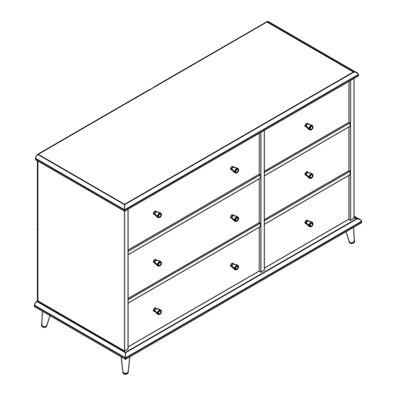
6 Drawer Dresser
Date of Purchase ___ / ___ / ___
Lot Number:
THIS INSTRUCTION BOOKLET CONTAINS IMPORTANT SAFETY INFORMATION. PLEASE READ AND KEEP FOR FUTURE REFERENCE.
Keep your home and family safe
with the wall anchor kit that is
included with the product.
Serious or fatal crushing injuries can
occur from tipping furniture.
WARNING: Manufacturer assumes no liability
for improper installation or excessive loads
placed on screws or bracket. This wall anchor
is not a substitute for proper adult supervision.
Do Not Return This Product!
Contact our customer service team for help first.
Call: 1-800-489-3351 (toll free)
Monday-Friday 9am - 5pm CST
Visit: www.ameriwoodhome.com
Easy
Assembly Difficulty Meter
B349237222COM0
Tough
Advertisement

Related Manuals for Otto 9237222COM


Summary of Contents for Otto 9237222COM
- Page 1 9237222COM 6 Drawer Dresser B349237222COM0 Date of Purchase ___ / ___ / ___ Lot Number: Do Not Return This Product! Contact our customer service team for help first. Call: 1-800-489-3351 (toll free) Monday-Friday 9am - 5pm CST Visit: www.ameriwoodhome.com THIS INSTRUCTION BOOKLET CONTAINS IMPORTANT SAFETY INFORMATION. PLEASE READ AND KEEP FOR FUTURE REFERENCE.
-
Page 2: Helpful Hints
Contact Us! Do NOT return this product! Contact our friendly customer service team first for help. Assembly Tips Call us! 1-800-489-3351 Monday-Friday 9am - 5pm CST Tube Visit ameriwoodhome.com to view the limited warranty valid in the U.S. and Canada. Helpful Hints PEOPLE NEEDED FOR ASSEMBLY: 2 ESTIMATED ASSEMBLY TIME: 2 HOURS... -
Page 3: Before You Start
Before You Start Read through each step carefully and follow the proper order Separate and count all your parts and hardware Give yourself enough room for the assembly process Have the following tools: Flat Head Screwdriver, #2 Phillips Head Screwdriver and Hammer Caution: If using a power drill or power screwdriver for screwing, please be aware to slow down and stop when screw is tight. - Page 4 Before You Start...
-
Page 5: Board Identification
Board Identification Not actual size Bottom 39237222030 39237222040 Left Panel Right Panel 39237222010 39237222020 Support (x2) Drawer Front (x3) 39100222060 39100222080 Small Support (x2) 39237222100 SIDE Divider 39237222090 Drawer Bottom (x3) Drawer Side (x12) Small Drawer Front (x3) 39991341068910D 39991167346200C 39237222110 BACK BACK... - Page 6 Board Identification Not actual size Back Panel K923700000 This piece is paperboard construction. It is not made from wood, but is required for the assembly of your unit. SIDE SIDE BACK BACK SIDE SIDE...
-
Page 7: Part List
Part List Actual Size Note: Your model may contain extra hardware. (x14) (x14) (x14) (x60) (x6) #A22620 #A22610 #A21670 #A11080 #A23030 cam lock cam bolt wood dowel confirmat screw 7/16" flat head screw (x15) (x60) (x24) (x9) #A12420 #A12120 (x9) #A21970 #A17400 5/8"... - Page 8 Part List Not Actual Size (x1) (x12) (x5) #A84050 #A54520 #A54800 Safety Bracket Kit drawer bracket foot bracket left cabinet member right cabinet member (x6) left drawer member #A54900 drawer brace (x5) right drawer member #A44320 foot (x6) drawer slide kit #A56770...
- Page 9 STEP 1 Marked with a "L" left cabinet member (x9) (x3) (x2) (x2) (x2) #A11080 #A56770 #A22610 #A22620 #A21670 Quick Assembly Proper orientation of CAM LOCK...
- Page 10 STEP 2 Marked with a "R" right cabinet member (x9) (x2) (x2) (x2) (x3) #A11080 #A56770 #A22610 #A22620 #A21670 Quick Assembly Proper orientation of CAM LOCK...
- Page 11 STEP 3 Marked with a "R" right cabinet member (x2) (x9) (x3) #A22610 #A11080 #A56770 left side...
- Page 12 STEP 4 Marked with a "L" left cabinet member (x9) (x2) (x2) (x2) (x3) #A11080 #A22610 #A22620 #A21670 #A56770 Quick Assembly Proper orientation of CAM LOCK right side...
- Page 13 STEP 5 Quick Assembly (x8) (x8) Proper orientation of CAM LOCK #A22620 #A21670...
- Page 14 STEP 6 finished edges face up...
- Page 15 STEP 7 finished edges face up...
- Page 16 STEP 8 (x6) (x1) #A22610 #A84050 Do not fully tighten screw.
- Page 17 STEP 9 finished edge...
- Page 18 STEP 10 (x6) #A23030 finished edge...
- Page 19 STEP 11 (x15) (x5) (x5) #A12420 #A54800 #A44320 Attach foot brackets (14) to bottom (D) with screws (10) as shown. Screw a foot (15) into each foot bracket (14) as shown.
- Page 20 STEP 12 IMPORTANT! THE BACK PANEL IS A STRUCTURAL PART OF THIS UNIT AND MUST BE INSTALLED PROPERLY. Carefully turn your unit over on it's front side. Attached the back panel as shown nailing straight into the raw edges. (x40) Assure that the unit is square.
- Page 21 STEP 13 (x24) (x12) #A12120 #A54520 SIDE SIDE...
- Page 22 STEP 14 (x24) #A12120 Center the groove in the drawer sides with the groove in the drawer front (H & K). SIDE SIDE You will apply this step for 3 large drawers and for 3 small drawers...
- Page 23 STEP 15 SIDE "finished surface" SIDE You will apply this step for 3 large drawers and for 3 small drawers...
- Page 24 STEP 16 (x24) #A21970 Tap the drive fasteners (8) lightly with a hammer to securely fasten. BACK SIDE SIDE You will apply this step for 3 large drawers and for 3 small drawers...
- Page 25 STEP 17 left drawer member right drawer member (x6) (x6) (x3) (x12) #A52365 #A17400 #A11080 #A56770 Attach the slides first then attach knob. SIDE SIDE...
- Page 26 STEP 18 left drawer member right drawer member (x3) (x3) (x3) (x12) #A52365 #A17400 #A11080 #A56770 Attach the slides first then attach knob. SIDE SIDE...
- Page 27 STEP 19 (x12) (x6) #A12120 #A54900 Attach drawer brace (17) to bottom of drawer as shown. BACK You will apply this step for 3 large drawers and for 3 small drawers...
- Page 28 STEP 20 For Masonry, Concrete, or other wall materials: Consult your local hardware store for appropriate anchors to securely (x1) attach the safety bracket. #A84050 IMPORTANT: THIS UNIT MUST BE SECURE TO THE WALL TO HELP PREVENT TIPOVER. FOLLOW THESE INSTRUCTIONS TO INSTALL THE ANTI-TIPPING SAFETY BRACKET PROVIDED WITH THIS PRODUCT.
- Page 29 STEP 21 Note: The drawer bracket holes are slotted. Drawer front can be adjusted by loosening screws, making needed adjustments and retightening screws. roller cabinet member drawer runner roller...
- Page 30 Maximum Loads This unit has been designed to support the maximum loads shown. Exceeding these load limits could cause sagging, instability, product collapse, and/or serious injury. 25 lbs 11.3 kg (each small drawer) 75 lbs 34 kg 35 lbs 15.9 kg (each large drawer) Warning: Risk of injury to persons - do not place a television on this furniture.
- Page 31 Register your product to receive the following: * New trend details - sneak peek on what's new * Surveys - have a voice within our community * Exclusive deals and discount codes * Quick and easy replacement part service To register your product, visit ameriwoodhome.com Visit your local retailer's website, rate your purchased product and leave us some feedback! We would like to extend a big "Thank You"...
- Page 32 Español Cubierta Delantera Este libro de instrucciones contiene información IMPORTANTE de seguridad. Por favor lea y manténgalo para referencia en el futuro. No Regrese este producto! Comuniquese con nuestro amistoso equipo de servicio al cliente para obtener ayuda. Llamenos al: 1-800-489-3351 (Gratis) Lunes - Viernes 9am - 5pm CST Visitar: www.ameriwoodhome.com PRECAUCION Este mueble puede volcarse y causar graves heridas y/o muerte.
- Page 33 Español Página 19 Fije los soportes de pata (14) a la parte inferior (D) con los tornillos (10) como se muestra. Atornille una pata (15) en cada soporte de pata (14) como se muestra. Página 20 Conecte los panel trasero como se muestra clavando directamente en los bordes sin procesar. Asegura qie e;...
- Page 34 Español OPCIÓN 1: acoplado a un travesaño de la pared (método recomendado) Ubica un travesaño en la pared utilizando un localizador de travesaños. Coloca tu unidad contra la pared, con el soporte de seguridad alineado en ese lugar. Para facilitar la entrada del tornillo, puedes perforar un agujero guía de 1/8"...
- Page 35 Français Couverture Avant CE LIVRET D'INSTRUCTION CONTIENT DES INFORMATIONS IMPORTANTES SUR LA SÉCURITÉ. VEUILLEZ LIRE ET GARDER POUR UNE RÉFÉRENCE FUTURE Ne retournez pas ce produit! Contactez notre équipe de service à la clientèle amicale d'abord pour obtenir de l'aide. Appelez-nous: 1-800-489-3351 (sans frais) du Lundi au Vendredi de 9h à...
- Page 36 Français Page 19 Fixez les supports de pied (14) en bas (D) avec les vis (10) comme indiqué. Vissez un pied (15) dans chaque support de pied (14) comme illustré. Page 20 Attachez les panneaux arrière comme indiqué en cliquant directement dans les bords bruts. Assurez-vous que le meuble està...
- Page 37 Français OPTION 1 : ancrage sur un colombage (méthode privilégiée) Localisez un colombage dans le mur à l'aide d'un détecteur de colombage. Placez votre meuble contre le mur en maintenant le support de sécurité aligné au meme endroit. Pour faciliter l'insertion de la vis, il est recommandé...
Need help?
Do you have a question about the 9237222COM and is the answer not in the manual?
Questions and answers